MERCEDES-BENZ E-Class COUPE 2017 C207 Owner's Manual
Manufacturer: MERCEDES-BENZ, Model Year: 2017, Model line: E-Class COUPE, Model: MERCEDES-BENZ E-Class COUPE 2017 C207Pages: 318, PDF Size: 7.35 MB
Page 301 of 318
tire pressure
Pressure inside the tire applying an outward
force to every square inch of the tire's surface.
The tire pressure is specified in pounds per
square inch (psi), in kilopascal (kPa) or in bar.
The tire pressure should only be corrected when
the tires are cold.
Cold tire pressure
The tires are cold:
Rif the vehicle has been parked with the tires
out of direct sunlight for at least three hours
and
Rif the vehicle has not been driven further than
1 mile (1.6 km)
Tread
The part of the tire that comes into contact with
the road.
Bead
The tire bead ensures that the tire sits securely
on the wheel. There are several steel wires in thebead to prevent the tire from coming loose from
the wheel rim.
Sidewall
The part of the tire between the tread and the
bead.
Weight of optional extras
The combined weight of those optional extras
that weigh more than the replaced standard
parts and more than 2.3 kg (5 lbs). These
optional extras, such as high-performance
brakes, level control, a roof rack or a high-per-
formance battery, are not included in the curb
weight and the weight of the accessories.
TIN (Tire Identification Number)
This is a unique identifier which can be used by
a tire manuf acturer to identify tires, for example
for a product recall, and thus identify the pur-
chasers. The TIN is made up of the manufactur- er's identity code, tire size, tire type code and
the manufacturing date.
Load bearing index
The load bearing index (also load index) is a code
that contains the maximum load bearing capa-
city of a tire.
Traction
Traction is the result of friction between the tires
and the road surface.
Treadwear indicators
Narrow bars (tread wear bars) that are distrib-
uted over the tire tread. If the tire tread is level
with the bars, the wear limit of áin (1.6 mm)
has been reached.
Occupant distribution
The distribution of occupants in a vehicle at their
designated seating positions.
Total load limit
Nominal load and luggage load plus 68 kg
(150 lbs) multiplied by the number of seats in
the vehicle.
Changing a wheel
Flat tire
The "Breakdown assistance" section
(Ypage 266 )contains information and notes on
how to deal with a flat tire. Information on driv-
ing with MOExtended tires in the event of a flat
tire can be found under "MOExtended tires (tires
with run-flat characteristics" (
Ypage 266).
Vehicle with emergency spare wheel: in the
event of a flat tire, the emergency spare wheel is
mounted as described under "Mounting a
wheel" (
Ypage 300).
Rotating the wheels
GWARNING
Interchanging the front and rear wheels may
severely impair the driving characteristics if
the wheels or tires have different dimensions. The wheel brakes or suspension components
may also be damaged. There is a risk of acci-
dent.
Rotate front and rear wheels only if the wheels and tires are of the same dimensions.
!On vehicles equipped with a tire pressure
monitor, electronic components are located
in the wheel.
Changing a wheel299
Wheels and tires
Z
Page 302 of 318
Tire-mounting tools should not be used near
the valve. This could damage the electronic
components.
Only have tires changed at a qualified spe-
cialist workshop.
Always observe the instructions and safety
notes in the "Mounting a wheel" section
(
Ypage 300).
The wear patterns on the front and rear tires
differ, depending on the operating conditions.
Rotate the wheels before a clear wear pattern
has formed on the tires. Front tires typically
wear more on the shoulders and the rear tires in the center.
On vehicles that have the same size front and
rear wheels, you can rotate the wheels accord-
ing to the intervals in the tire manufacturer's
warranty book in your vehicle documents. If no
warranty book is available, the tires should be
rotated every 3,000 to 6,000 miles (5,000 to
10,000 km). Depending on tire wear, this may
be required earlier. Do not change the direction
of wheel rotation.
Clean the contact surfaces of the wheel and the
brake disc thoroughly every time a wheel is rota-
ted. Check the tire pressure and reactivate the
tire pressure monitor if necessary (
Ypage 289).
Direction of rotation
Tires with a specified direction of rotation have
additional benefits, e.g. if there is a risk of hydro-
planing. These advantages can only be gained if
the tires are installed corresponding to the
direction of rotation.
An arrow on the sidewall of the tire indicates its
correct direction of rotation.
Storing wheels
Store wheels that are not being used in a cool,
dry and preferably dark place. Protect the tires
from oil, grease, gasoline and diesel.
Mounting a wheel
Preparing the vehicle
XStop the vehicle on solid, non-slippery and
level ground.
XApply the parking brake.
XBring the front wheels into the straight-ahead
position.
XShift the transmission to position P.
XSwitch off the engine.
XRemove the SmartKey from the ignition lock.
or, on vehicles with KEYLESS‑ GO:
XOpen the driver's door.
The on-board electronics now have status 0.
This is the same as the SmartKey having been
removed.
XRemove the Start/Stop button from the igni-
tion lock (Ypage 122).
XIf included in the vehicle equipment, remove
the tire-change tool kit from the vehicle
(
Ypage 266).
XSafeguard the vehicle against rolling away.
Securing the vehicle to prevent it from
rolling away
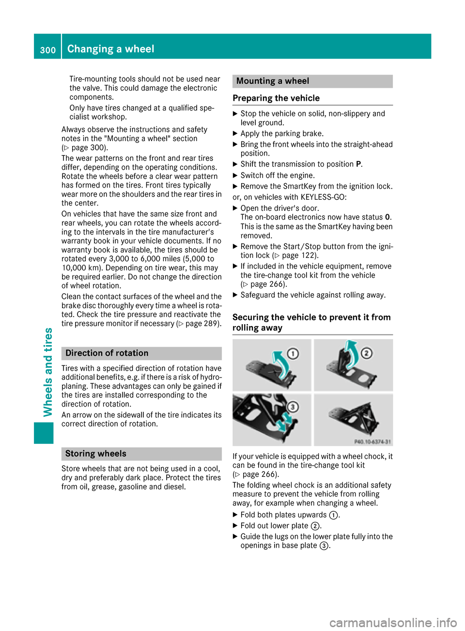
If your vehicle is equipped with a wheel chock, it
can be found in the tire-change tool kit
(
Ypage 266).
The folding wheel chock is an additional safety
measure to prevent the vehicle from rolling
away, for example when changing a wheel.
XFold both plates upwards :.
XFold out lower plate;.
XGuide the lugs on the lower plate fully into the
openings in base plate =.
300Changing a wheel
Wheels and tires
Page 303 of 318
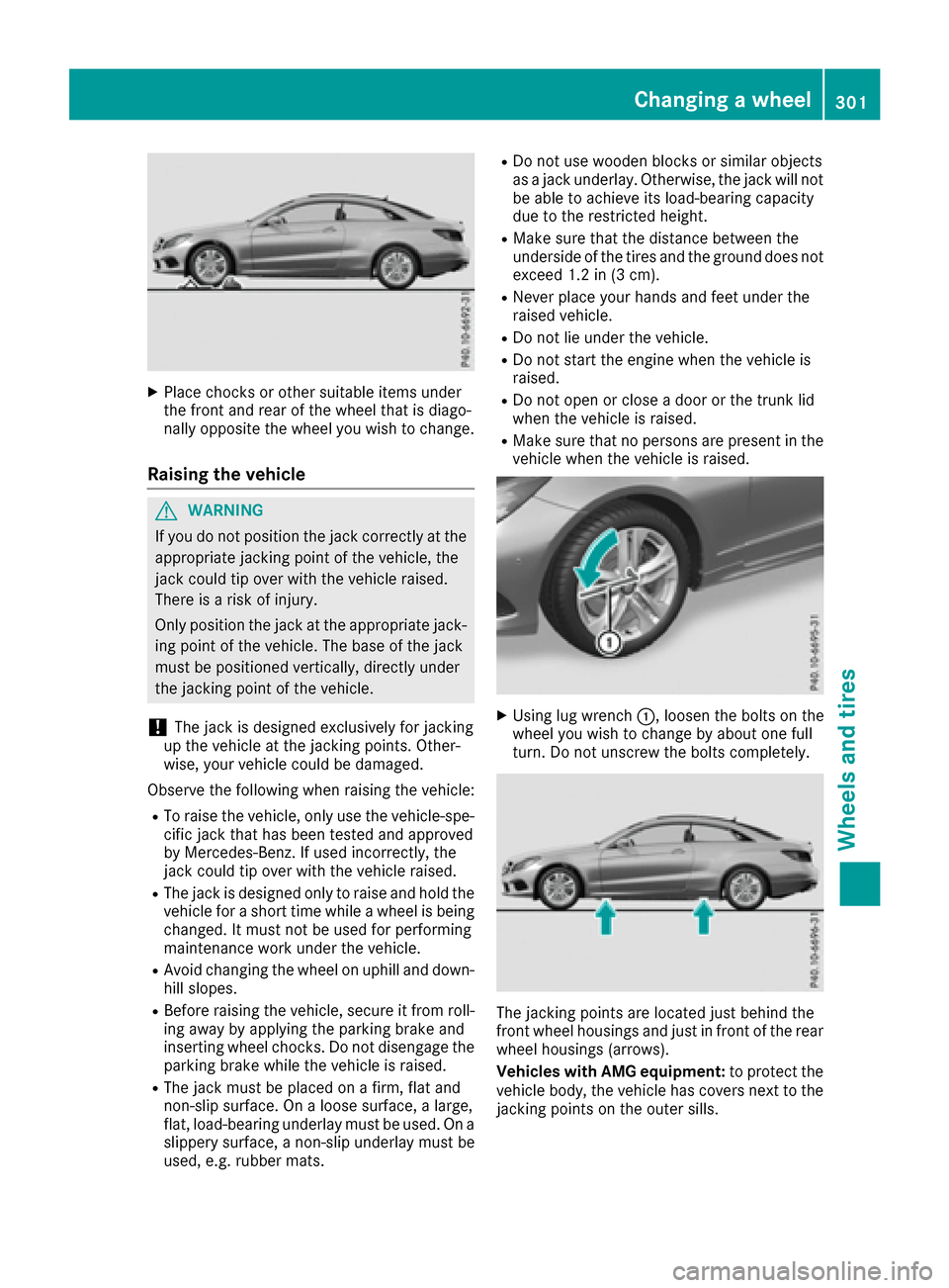
XPlace chocks or other suitable items under
the front and rear of the wheel that is diago-
nally opposite the wheel you wish to change.
Raising the vehicle
GWARNING
If you do not position the jack correctly at the
appropriate jacking point of the vehicle, the
jack could tip over with the vehicle raised.
There is a risk of injury.
Only position the jack at the appropriate jack-
ing point of the vehicle. The base of the jack
must be positioned vertically, directly under
the jacking point of the vehicle.
!The jack is designed exclusively for jacking
up the vehicle at the jacking points. Other-
wise, your vehicle could be damaged.
Observe the following when raising the vehicle:
RTo raise the vehicle, only use the vehicle-spe-
cific jack that has been tested and approved
by Mercedes-Benz. If used incorrectly, the
jack could tip over with the vehicle raised.
RThe jack is designed only to raise and hold the
vehicle for a short time while a wheel is being
changed. It must not be used for performing
maintenance work under the vehicle.
RAvoid changing the wheel on uphill and down-
hill slopes.
RBefore raising the vehicle, secure it from roll-
ing away by applying the parking brake and
inserting wheel chocks. Do not disengage the
parking brake while the vehicle is raised.
RThe jack must be placed on a firm, flat and
non-slip surface. On a loose surface, a large,
flat, load-bearing underlay must be used. On a
slippery surface, a non-slip underlay must be
used, e.g. rubber mats.
RDo not use wooden blocks or similar objects
as a jack underlay. Otherwise, the jack will not
be able to achieve its load-bearing capacity
due to the restricted height.
RMake sure that the distance between the
underside of the tires and the ground does not
exceed 1.2 in (3 cm).
RNever place your hands and feet under the
raised vehicle.
RDo not lie under the vehicle.
RDo not start the engine when the vehicle is
raised.
RDo not open or close a door or the trunk lid
when the vehicle is raised.
RMake sure that no persons are present in the
vehicle when the vehicle is raised.
XUsing lug wrench :, loosen the bolts on the
wheel you wish to change by about one full
turn. Do not unscrew the bolts completely.
The jacking points are located just behind the
front wheel housings and just in front of the rear
wheel housings (arrows).
Vehicles with AMG equipment: to protect the
vehicle body, the vehicle has covers next to the
jacking points on the outer sills.
Changing a wheel301
Wheels and tires
Z
Page 304 of 318
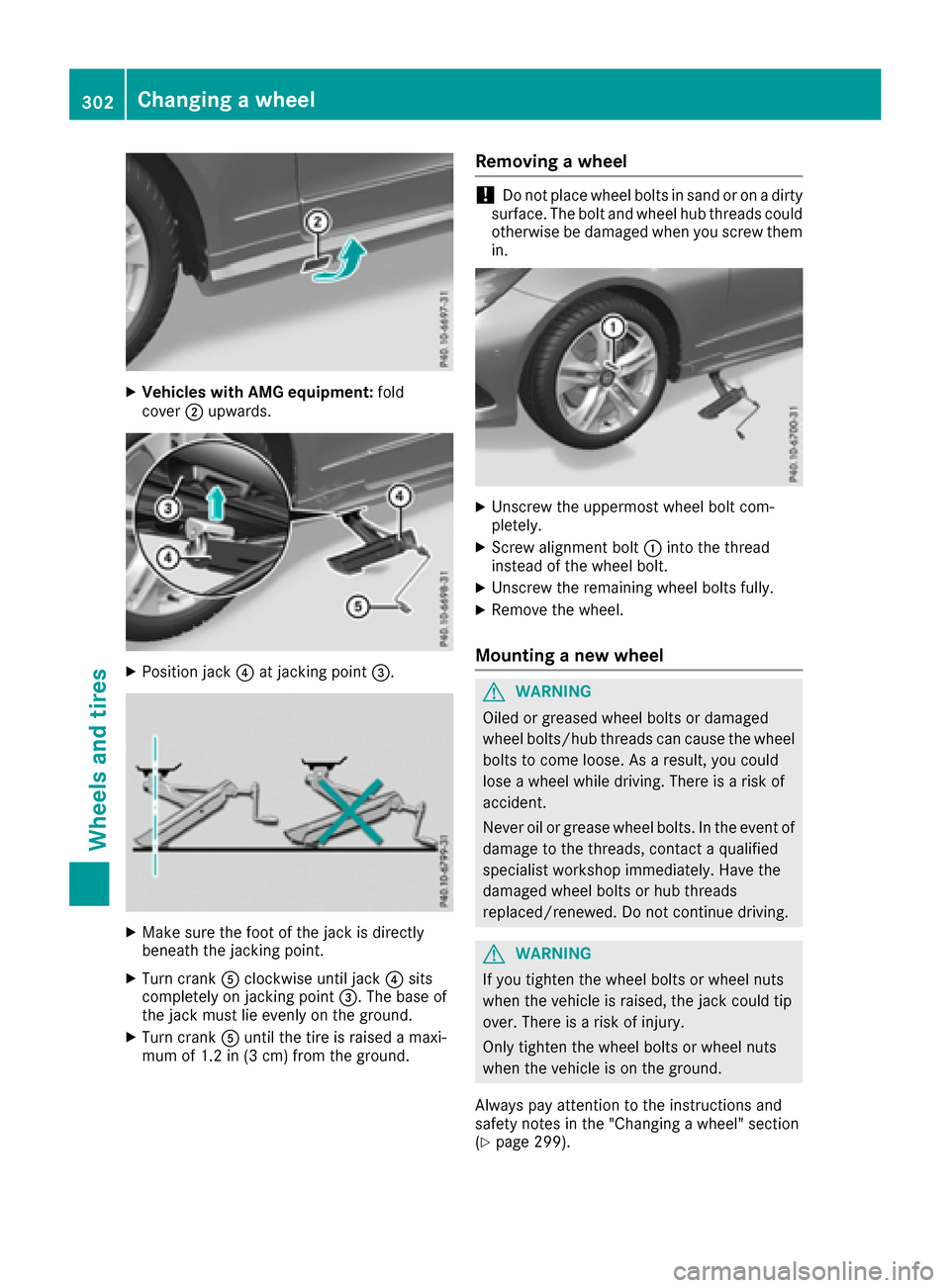
XVehicles with AMG equipment:fold
cover ;upwards.
XPosition jack ?at jacking point =.
XMake sure the foot of the jack is directly
beneath the jacking point.
XTurn crankAclockwise until jack ?sits
completely on jacking point =. The base of
the jack must lie evenly on the ground.
XTurn crank Auntil the tire is raised a maxi-
mum of 1.2 in (3 cm) from the ground.
Removing a wheel
!Do not place wheel bolts in sand or on a dirty
surface. The bolt and wheel hub threads could
otherwise be damaged when you screw them
in.
XUnscrew the uppermost wheel bolt com-
pletely.
XScrew alignment bolt :into the thread
instead of the wheel bolt.
XUnscrew the remaining wheel bolts fully.
XRemove the wheel.
Mounting a new wheel
GWARNING
Oiled or greased wheel bolts or damaged
wheel bolts/hub threads can cause the wheel bolts to come loose. As a result, you could
lose a wheel while driving. There is a risk of
accident.
Never oil or grease wheel bolts. In the event of
damage to the threads, contact a qualified
specialist workshop immediately. Have the
damaged wheel bolts or hub threads
replaced/renewed. Do not continue driving.
GWARNING
If you tighten the wheel bolts or wheel nuts
when the vehicle is raised, the jack could tip
over. There is a risk of injury.
Only tighten the wheel bolts or wheel nuts
when the vehicle is on the ground.
Always pay attention to the instructions and
safety notes in the "Changing a wheel" section
(
Ypage 299).
302Changing a wheel
Wheels and tires
Page 305 of 318
Only use wheel bolts that have been designed
for the wheel and the vehicle. For safety rea-
sons, Mercedes-Benz recommends that you
only use wheel bolts which have been approved
for Mercedes-Benz vehicles and the respective
wheel.
!To prevent damage to the paintwork, hold
the wheel securely against the wheel hub
while screwing in the first wheel bolt.
XClean the wheel and wheel hub contact sur-
faces.
XSlide the wheel to be mounted onto the align-
ment bolt and push it on.
XTighten the wheel bolts until they are finger-
tight.
XUnscrew the alignment bolt.
XTighten the last wheel bolt until it is finger-
tight.
Lowering the vehicle
GWARNING
The wheels could work loose if the wheel nuts and bolts are not tightened to the specified
tightening torque. There is a risk of accident.
Have the tightening torque immediately
checked at a qualified specialist workshop
after a wheel is changed.
XTurn the crank of the jack counter-clockwise
until the vehicle is once again standing firmly
on the ground.
XPlace the jack to one side.
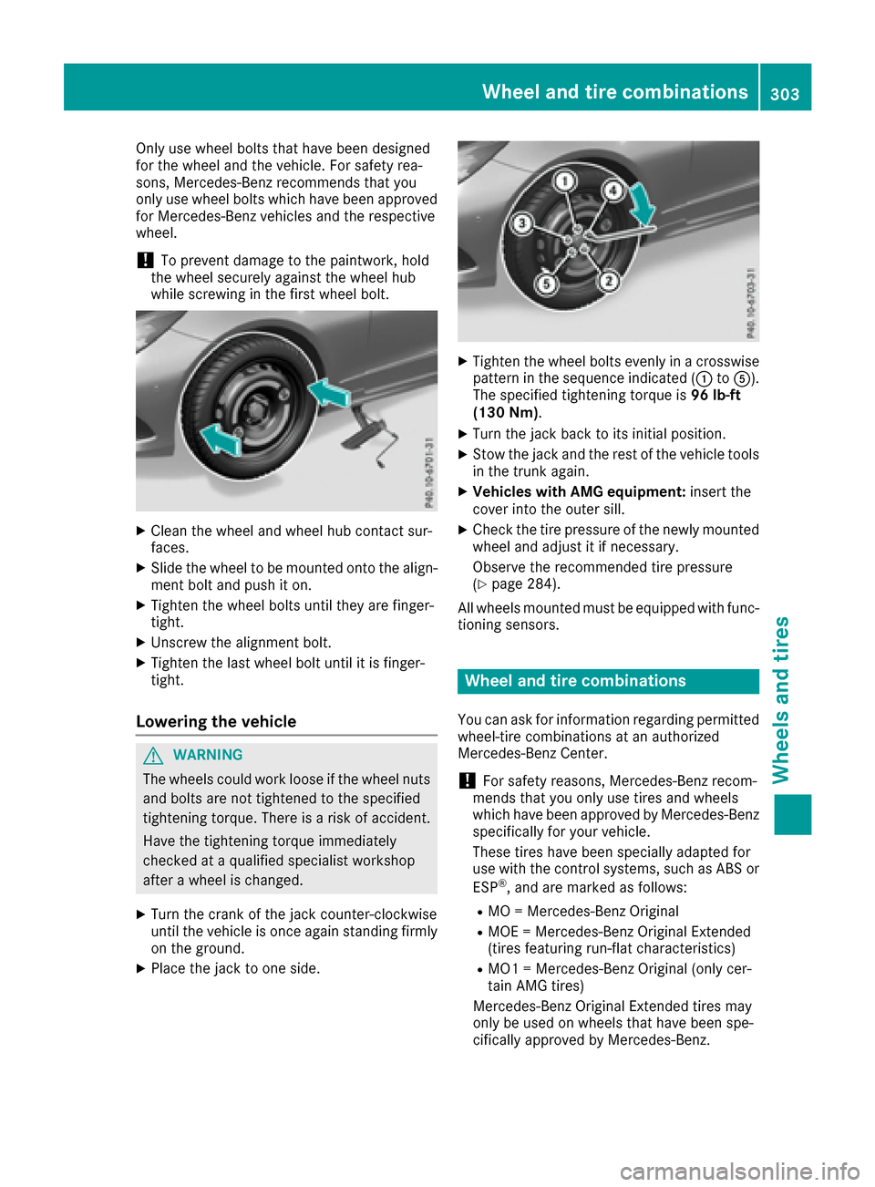
XTighten the wheel bolts evenly in a crosswisepattern in the sequence indicated (: toA).
The specified tightening torque is 96 lb-ft
(130 Nm) .
XTurn the jack back to its initial position.
XStow the jack and the rest of the vehicle tools
in the trunk again.
XVehicles with AMG equipment: insert the
cover into the outer sill.
XCheck the tire pressure of the newly mounted
wheel and adjust it if necessary.
Observe the recommended tire pressure
(
Ypage 284).
All wheels mounted must be equipped with func-
tioning sensors.
Wheel and tire combinations
You can ask for information regarding permitted
wheel-tire combinations at an authorized
Mercedes-Benz Center.
!For safety reasons, Mercedes-Benz recom-
mends that you only use tires and wheels
which have been approved by Mercedes-Benz
specifically for your vehicle.
These tires have been specially adapted for
use with the control systems, such as ABS or
ESP
®, and are marked as follows:
RMO = Mercedes-Benz Original
RMOE = Mercedes-Benz Original Extended
(tires featuring run-flat characteristics)
RMO1 = Mercedes-Benz Original (only cer-
tain AMG tires)
Mercedes-Benz Original Extended tires may
only be used on wheels that have been spe-
cifically approved by Mercedes-Benz.
Wheel and tire combinations303
Wheels and tires
Z
Page 306 of 318
Only use tires, wheels or accessories tested
and approved by Mercedes-Benz. Certain
characteristics, e.g. handling, vehicle noise
emissions or fuel consumption, may other-
wise be adversely affected. In addition, when
driving with a load, tire dimension variations
could cause the tires to come into contact
with the bodywork and axle components. This
could result in damage to the tires or the vehi-
cle.
Mercedes-Benz accepts no liability for dam-
age resulting from the use of tires, wheels or
accessories other than those tested and
approved.
Information on tires, wheels and approved
combinations can be obtained from any quali-
fied specialist workshop.
!Retreaded tires are neither tested nor rec-
ommended by Mercedes-Benz, since previ-
ous damage cannot always be detected on
retreaded tires. As a result, Mercedes-Benz
cannot guarantee vehicle safety if retreaded
tires are mounted. Do not mount used tires if
you have no information about their previous usage.
The recommended pressures for various oper-
ating conditions can be found:
Ron the Tire and Loading Information placard
on the B-pillar on the driver's side
Rin the tire pressure table in the fuel filler flap
Observe the notes on recommended tire pres-
sures under various operating conditions
(
Ypage 284).
Check tire pressures regularly, and only when
the tires are cold. Comply with the maintenance
recommendations of the tire manufacturer in
the vehicle document wallet.
Notes on the vehicle equipment – always equip the vehicle with:
Rwith tires of the same size on a given axle (left
and right)
Rthe same type of tires at a given time (summer
tires, winter tires, MOExtended tires)
Exception: it is permissible to install a differ-
ent type or make in the event of a flat tire.
Observe the "MOExtended tires (tires with
run-flat characteristics" section (
Ypage 266).
Vehicles equipped with MOExtended tires are
not equipped with a TIREFIT kit at the factory. It
is therefore recommended that you additionally
equip your vehicle with a TIREFIT kit if you mount tires that do not feature run-flat properties, e.g. winter tires. A TIREFIT kit may be obtained from
a qualified specialist workshop.
Emergency spare wheel
Important safety notes
GWARNING
The wheel or tire size as well as the tire type of the spare wheel or emergency spare wheel
and the wheel to be replaced may differ.
Mounting an emergency spare wheel may
severely impair the driving characteristics.
There is a risk of an accident.
To avoid hazardous situations:
Radapt your driving style accordingly and
drive carefully.
Rnever mount more than one spare wheel or
emergency spare wheel that differs in size.
Ronly use a spare wheel or emergency spare
wheel of a different size briefly.
Rdo not switch ESP®off.
Rhave a spare wheel or emergency spare
wheel of a different size replaced at the
nearest qualified specialist workshop.
Observe that the wheel and tire dimensions
as well as the tire type must be correct.
When using an emergency spare wheel or spare
wheel of a different size, you must not exceed
the maximum speed of 50 mph (80 km/h).
Snow chains must not be mounted on emer-
gency spare wheels.
General notes
You can ask for information regarding permitted
emergency spare wheels at an authorized
Mercedes-Benz Center.
You should regularly check the pressure of the
emergency spare wheel, particularly prior to
long trips, and correct the pressure as neces-
sary (
Ypage 284). The value on the wheel is
valid.
An emergency spare wheel may also be moun-
ted against the direction of rotation. Observe
the time restriction on use as well as the speed
304Emergency spare wheel
Wheels and tires
Page 307 of 318
limitation specified on the emergency spare
wheel.
Replace the tires after six years at the latest,
regardless of wear. This also applies to the
emergency spare wheel.
iWhen you are driving with the emergency
spare wheel mounted, the tire pressure mon-
itor cannot function reliably. Only restart the
tire pressure monitor when the defective
wheel has been replaced with a new wheel.
If an emergency spare wheel is mounted, the
system may continue to show the tire pres-
sure of the wheel that has been removed for a
few minutes. The value displayed for the
mounted emergency spare wheel is not the
same as the current tire pressure of the emer-
gency spare wheel.
"Minispare" emergency spare wheel
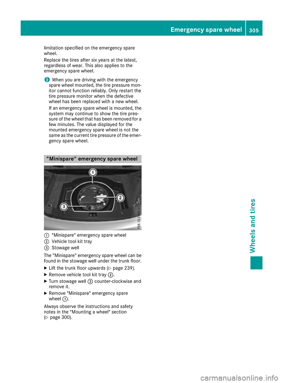
:"Minispare" emergency spare wheel
;Vehicle tool kit tray
=Stowage well
The "Minispare" emergency spare wheel can be
found in the stowage well under the trunk floor.
XLift the trunk floor upwards (Ypage 239).
XRemove vehicle tool kit tray ;.
XTurn stowage well=counter-clockwise and
remove it.
XRemove "Minispare" emergency spare
wheel :.
Always observe the instructions and safety
notes in the "Mounting a wheel" section
(
Ypage 300).
Emergency spare wheel305
Wheels and tires
Z
Page 308 of 318
Information regarding technical data
i
The dat astate dher especifically refers to a
vehicl ewit hstandard equipment. Consult an
authorize dMercedes-Ben zCente rfor th e
dat afor all vehicl evariants and trim levels.
Vehicle electronics
Installing two-way radios and mobile
phones (RF transmitters)
GWARNIN G
The electromagneti cradiation from modifie d
or incorrectl yretrofitte dRF-transmitters can
interfere wit hth evehicl eelectronics .This can
compromise th eoperational safet yof th e
vehicle. Ther eis aris kof an accident.
You should hav eall wor kto electrical and
electronic equipmen tcarried out at aqualified
specialist workshop.
GWARNIN G
The electromagneti cradiation from incor-
rectl yoperate dRF transmitters can interfere
wit hth evehicl eelectronics ,for example:
Rif th eRF transmitte ris no tconnecte dwit h
an exterio rantenna
Rth eexterio rantenna has been installed
incorrectl yor is no t alow-reflection typ e
This can compromise th eoperational safet y
of th evehicle. Ther eis aris kof an accident.
Hav eth elow-reflection exterio rantenna
mounte dat aqualified specialist workshop.
When operating RF transmitters in th evehi-
cle ,always connec tthem wit hth elow-reflec -
tion exterio rantenna.
!The operating permit may be invalidated if
th einstruction sfor installation and use of RF
transmitters are no tobserved. In particular, th
efollowin gcondition smust be
complied with:
Ronly approve dwavebands may be used.
Rcomplianc ewit hth emaximum permissible
output in these wavebands is required.
Ronly approve dantenna position smay be
used.
Excessiv elevels of electromagneti cradiation
may caus edamag eto your healt hand th ehealt h
of others. Using an exterio rantenna takes int o
accoun tcurren tscientific discussion srelating
to th epossible healt hhazards tha
t may result
from electromagneti cfields.
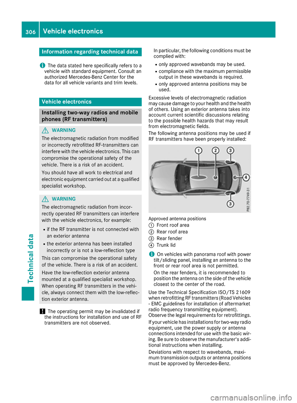
The followin gantenna position smay be used if
RF transmitters hav ebeen properly installed:
Approved antenna position s
:
Fron troo farea
;Rear roo farea
=Rear fender
?Trun klid
iOn vehicles wit hpanoram aroo fwit hpower
tilt/slidin gpanel, installin gan antenna to th e
fron tor rear roo farea is no tpermitted.
On th erear fenders, it is recommended to
position th eantenna on th eside of th evehicl e
closes tto th ecenter of th eroad .
Use th eTechnical Specification ISO/TS 2160 9
when retrofitting RF transmitters (Road Vehicles
- EM Cguidelines for installation of aftermarket
radi ofrequency transmitting equipment) .
Observ eth elegal requirements for retrofittings.
If your vehicl ehas installation sfor two-way radi o
equipment, use th epower suppl yor antenna
connection sintended for use wit hth ebasic wir-
ing .Be sur eto observ eth emanufacturer' saddi-
tional instruction swhen installing.
Deviation swit hrespec tto wavebands, maxi-
mum transmission output sor antenna position s
must be approve dby Mercedes-Benz.
306Vehicle electronics
Technical data
Page 309 of 318
The maximum transmission output (PEAK) at the
base of the antenna must not exceed the values
in the following table:
The maximum transmission output (PEAK) at the
base of the antenna must not exceed the fol-
lowing values:
WavebandMaximum
transmission output
Short wave
3 - 54 MHz100 W
4 m waveband
74 - 88 MHz30 W
2 m waveband
144 - 174 MHz50 W
Trunked radio/Tetra
380 - 460 MHz10 W
70 cm waveband
400 - 460 MHz35 W
Mobile communications
(3G/3G/4G)10 W
The following can be used in the vehicle without
restrictions:
RRF transmitters with a maximum transmis-
sion output of up to 100 mW
RRF transmitters with transmitter frequencies
in the 380 - 410 MHz waveband and a maxi-
mum transmission output of up to 2 W
(trunked radio/Tetra)
RMobile telephones (2G/3G/4G)
There is no restriction for antenna positions on
the outside of the vehicle for the following wave-
bands:
RTrunked radio/Tetra
R70 cm waveband
R2G/3G/4G
Identification plates
Vehicle identification plate with vehi-
cle identification number (VIN)
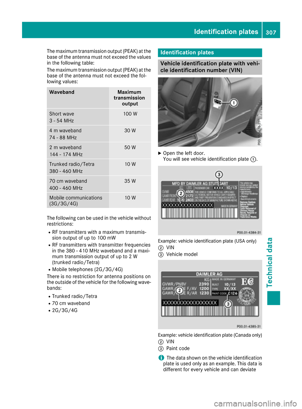
XOpen the left door.
You will see vehicle identification plate :.
Example: vehicle identification plate (USA only)
;
VIN
=Vehicle model
Example: vehicle identification plate (Canada only)
;
VIN
=Paint code
iThe data shown on the vehicle identification
plate is used only as an example. This data is
different for every vehicle and can deviate
Identification plates307
Technical data
Z
Page 310 of 318
from the data shown here. You can find the
data applicable to your vehicle on the vehicle
identification plate.
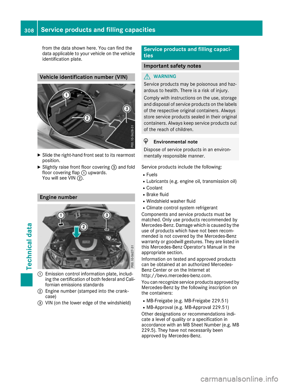
Vehicle identification number (VIN)
XSlide the right-hand front seat to its rearmost
position.
XSlightly raise front floor covering=and fold
floor covering flap :upwards.
You will see VIN ;.
Engine number
:Emission control information plate, includ-
ing the certification of both federal and Cali-
fornian emissions standards
;Engine number (stamped into the crank-
case)
=VIN (on the lower edge of the windshield)
Service products and filling capaci-
ties
Important safety notes
GWARNING
Service products may be poisonous and haz-
ardous to health. There is a risk of injury.
Comply with instructions on the use, storage
and disposal of service products on the labels
of the respective original containers. Always
store service products sealed in their original
containers. Always keep service products out
of the reach of children.
HEnvironmental note
Dispose of service products in an environ-
mentally responsible manner.
Service products include the following:
RFuels
RLubricants (e.g. engine oil, transmission oil)
RCoolant
RBrake fluid
RWindshield washer fluid
RClimate control system refrigerant
Components and service products must be
matched. Only use products recommended by
Mercedes-Benz. Damage which is caused by the
use of products which have not been recom-
mended is not covered by the Mercedes-Benz
warranty or goodwill gestures. They are listed in
this Mercedes-Benz Operator's Manual in the
appropriate section.
Information on tested and approved products
can be obtained at an authorized Mercedes-
Benz Center or on the Internet at
http://bevo.mercedes-benz.com.
You can recognize service products approved by
Mercedes-Benz by the following inscription on
the containers:
RMB-Freigabe (e.g. MB-Freigabe 229.51)
RMB-Approval (e.g. MB-Approval 229.51)
Other designations or recommendations indi-
cate a level of quality or a specification in
accordance with an MB Sheet Number (e.g. MB 229.5). They have not necessarily been
approved by Mercedes-Benz.
308Service products and filling capacities
Technical data