load capacity MERCEDES-BENZ E-CLASS COUPE 2017 Owners Manual
[x] Cancel search | Manufacturer: MERCEDES-BENZ, Model Year: 2017, Model line: E-CLASS COUPE, Model: MERCEDES-BENZ E-CLASS COUPE 2017Pages: 541, PDF Size: 10.71 MB
Page 230 of 541
#
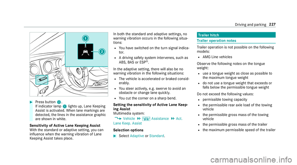
Press button 2.
If indicator lamp 1lights up, Lane Keeping
Assist is activated. When lane markings are
de tected, the lines in the assis tance graphic
are shown in white.
Sensitivity of Active Lane Keeping Assist
Wi th th est andard or adaptive setting, you can
influence when thewa rning vibration of Lane
Ke eping Assist take s place. In bo
th thest andard and adaptive settings, no
wa rning vibration occurs in thefo llowing situa‐
tions:
R You ha veswitched on the turn signal indica‐
to r.
R A driving sa fety sy stem inter venes, su chas
ABS, BAS or ESP ®
.
In the adaptive setting, there will also be no
wa rning vibration in thefo llowing situations:
R The vehicle is accelerated or braked consid‐
erably.
R Yousteer actively, e.g. swer vetoavo id an
obs tacle or change lane quickl y.
R You cut the corner on a sharp bend.
Setting the sensitivity of Active Lane Keep‐
ing Assist
Multimedia sy stem:
, Vehicle .
k Assistance .
Act.
Lane Keep. Assist
Selection options #
Select Adaptive orStandard. Tr
ailer hitch Tr
ailer operation no tes Tr
ailer operation is not possible on thefo llowing
models:
R AMG Line vehicles
Obser vethefo llowing no tes on theto ngue
we ight:
R use a tongue weight as close as possible to
th e maximum tongue weight
R do not use a tongue weight that exceeds or
fa lls below the permissible tongue weight
Do not exceed thefo llowing values:
R permissible towing capacity
R the permissible rear axle load of theto wing
ve hicle
R the permissible gross mass of theto wing
ve hicle
R the permissible gross mass of the trailer
R the maximum permissible speed of the trailer Driving and parking
227
Page 234 of 541
%
Accessories can be connected tothe perma‐
nent po wer supp lyand the po wer supply that
is swit ched on via the ignition lock with max‐
imum po wer consum ptions of 180W.
Un coupling a trailer &
WARNING Risk of being crushed and
becoming trapped when uncoupling a
trailer
When uncoupling a trailer wi than engaged
ine rtia-activated brake, your hand may
become trapped between theve hicle and the
trailer dr awbar. #
Do not uncouple trailers with an
engaged overrun brake. &
WARNING Risk of becoming trapped
when disconnecting the trailer cable
Ve hicles with le vel control sy stem: the
ve hicle lo werswhen the trailer cable is dis‐
connected. This could
result in you or other people
becoming trapped if your or their limbs are
between theve hicle body and the tyres or
underneath theve hicle. #
Make sure nobody is underneath the
ve hicle or in the immediate vicinity of
th e wheel ar ches when you disconnect
th e trailer cable. *
NO
TEDama getothere ar bumper from
ins talling adap ter cables or adapte r plugs The
following parts could be damaged when
re tracting the ball neck fully electrically:
R bumper
R adap ter cable
R adapte r plug #
Alw aysre mo vethe adap ter cable or
adapte r plug before retracting the ball
neck fully electrically. #
Safeguard the trailer against rolling away. #
Disconnect the electrical connection
between theve hicle and the trailer. #
Uncouple the trailer. #
Place the pr otective co ver on the ball head. Bicycle
rack &
WARNING Risk of an accident when
using the bicycle rack incor rectly
The bicycle rack may become de tach ed from
th eve hicle in thefo llowing cases:
R the permissible load capacity of the
trailer hitch is exceeded.
R the bicycle rack is used incor rectl y.
R the bicycle rack is secured tothe ball
neck beneath the ball head.
Obser vethefo llowing foryo ur ow n sa fety
and that of other road users:
R always adhere tothe permissible load
capacity of the trailer hitch. Driving and parking
231
Page 235 of 541
R
only use the bicycle rack totranspo rt
bicycles.
R Alw ays proper lysecure the bicycle rack
by attaching it tothe ball head.
R only use bicycle rack s appr ovedby
Mercedes-Benz.
R always obser vethe bicycle rack operating
instructions. *
NO
TEDama getoor crac kson the trailer
hitch due tounsuitable bic ycle rack s or
bicycle rack s being used incor rectly #
Only use bicycle rack s appr ovedby
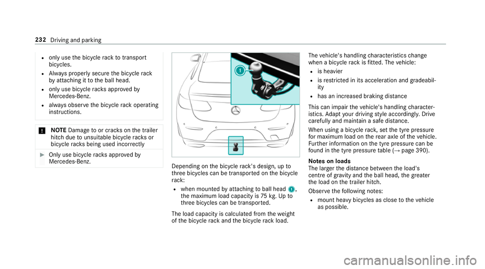
Mercedes-Benz. Depending on
the bicycle rack 's design, up to
th re e bicycles can be transpor ted on the bicycle
ra ck:
R when moun tedby attaching toball head 1,
th e maximum load capacity is 75kg.Up to
th re e bicycles can be transpor ted.
The load capacity is calculated from thewe ight
of the bicycle rack and the bicycle rack load. The
vehicle's handling characteristics change
when a bicycle rack isfitted. The vehicle:
R is heavier
R isrestricted in its accele ration and gradeabil‐
ity
R has an increased braking di stance
This can impair theve hicle's handling character‐
istics. Adapt your driving style accordingly. Drive
carefully and maintain a safe dis tance.
When using a bicycle rack , set the tyre pressure
fo r maximum load on there ar axle of theve hicle.
Fu rther information on the tyre pressure can be
fo und in the tyre pressure table (→ page 390).
Note s on loads
The larger the dis tance between the load's
cent reof gr avity and the ball head, the greater
th e load on the trailer hitch.
Obser vethefo llowing no tes:
R mount heavy bicycles as close totheve hicle
as possible. 232
Driving and parking
Page 400 of 541
&
WARNING Risk of accident due toincor‐
re ct dimensions of wheels and tyres
If wheels and tyres of the wrong size are
used, the wheel brakes or wheel suspension
components may become damaged. #
Alw aysre place wheels and tyres with
th ose that fulfil the specifications of the
original part.
When replacing wheels, make sure tofit the
cor rect:
R Designation
R Type
When replacing tyres, make sure tofit the
cor rect:
R Designation
R Manufactu rer
R Type &
WARNING Risk of inju rythro ugh exceed‐
ing the specified tyre load-bearing capa‐
city or the permissible speed rating
Exceeding the specified tyre load-bearing
capacity or the permissible speed rating may
lead totyre dama geand tothe tyres bur st‐
ing. #
Therefore, only use tyre types and sizes
appr ovedfo ryo ur vehicle model. #
Obser vethe tyre load-bearing capacity
ra ting and speed rating requ iredfor
yo ur vehicle. *
NO
TEDama getovehicle and tyres due
to non-app rove d tyre types and sizes Fo
r saf etyre asons, on lyuse wheels, tyres
and accessories which ha vebeen appr oved
fo ryo ur vehicle byMercedes-Benz. These tyres ha
vebeen specially adap tedfor
use with the control sy stems, e.g. ABS or
ESP ®
, and are mar ked as follo ws:
R MO = Mercedes-Benz Original
R MOE = Mercedes-Benz Original Extended
(run-flat tyres only for cer tain wheels)
R MO1 = Mercedes-Benz Original (only cer‐
tain AMG tyres)
Cer tain characteristics, e.g. handling, vehicle
noise emissions or fuel consum ption, may
ot herwise be adversely af fected. In addition,
when driving wi tha load, tyre dimension var‐
iations could cause the tyres tocome into
contact wi th the body and axle components.
This could result in damage tothe tyres or
th eve hicle.
Only use tyres, wheels or accessories tested
and appr oved byMercedes-Benz. Wheels and tyres
397
Page 403 of 541
may se
verely impair the driving characteris‐
tics.
The disk brakes or wheel suspension compo‐
nents may also be damaged. #
Rotate front and rear wheels on lyifthe
wheels and tyres are of the same
dimensions. Inter
changing the front and rear wheels if the
wheels or tyres ha vediffere nt dimensions can
re nder thege neral operating pe rmit in valid.
The wear pat tern s on the front and rear wheels
dif fer:
R Front wheels wear more on the shoulder of
th e tyre
R Rear wheels wear more in the cent reofthe
tyre
On vehicles with the same front and rear wheel
size, you can inter change the wheels every
5000 to10000 km, depending on thewe ar.
Ensure the direction of rotation is maintained for
th e wheels. It is imperative
toobser vethe instructions and
saf ety no tes on "Wheel change" when doing so. Note
s onstoring wheels R
Afterre moving wheels, store them in a cool,
dry and preferably dark place.
R Protect the tyres from conta ct withoil,
grease or fuel. Overview of
the ty re-change tool kit Apart from some countr
y-specific variants, vehi‐
cles are not equipped with a tyre-change tool kit.
Fo r more information on which tyre-changing
to ols are requ ired and appr ovedfo r per form ing a
wheel change on your vehicle, consult a qualified
specialist workshop.
Necessary tyre-changing tools may include, for
ex ample:
R Jack
R Chock
R Wheel spanner
R Cent ring pin %
The jack weighs appr oximately 3.4 kg.
The maximum load capacity of the jack can
be found on thest icke r af fixe dto the jac k.
The jack is maintenance-free. If there is a
malfunction, please conta ct aqualified spe‐
cialist workshop.
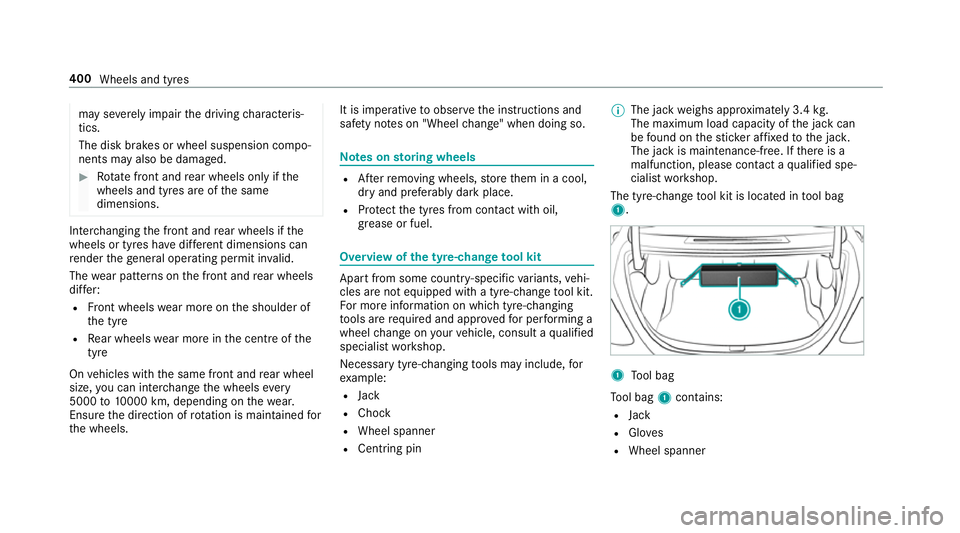
The tyre-change tool kit is located in tool bag
1. 1
Tool bag
To ol bag 1contains:
R Jack
R Gloves
R Wheel spanner 400
Wheels and tyres
Page 424 of 541
We
ights and loads Please no
tethat forth e specified vehicle data:
R items of optional equipment increase the
unladen weight and reduce the maximum
pa yload.
R vehicle-specific weight information can be
fo und on theve hicle identification plate .
Ro of load All models
Maximum
roof load 75kg Tr
ailer hitch Gene
ral no tes on the trailer hit ch Not all models can be used
to tow a trailer
(→ page 227).
Modifications tothe engine cooling sy stem may
be necessar y,depending on theve hicle model.
The retrofitting of a trailer hitch is only pe rmissi‐
ble if a towing capacity is specified in your vehi‐
cle documents. Fu
rther information on the trailer hitch can be
obtained at a qualified specialist workshop. Pe
rm issible towing capacity The
tongue weight is not included in theto wing
capacity.
Pe rm issible towing capacit y,braked (at a
minimum start-off gradeability of 8%) Model
Perm issible towing
capacit y,braked
E 200, manual trans‐
mission 15
00 kg
All other models 1800 kg Pe
rm issible towing capacit y,braked (at a
minimum start-off gradeability of 12%) Model
Perm issible towing
capacit y,braked
E 200, manual trans‐
mission 15
00 kg
All other models 1800 kg Pe
rm issible towing capacit y,unbraked Model
Perm issible towing
capacit y,unbraked
All model s7 50kg Maximum
tongue weight *
NO
TEDama gecaused bythe trailer
coming loose If
th eto ngue weight used is too lo w,the
trailer may come loose. Te
ch nical da ta421
Page 531 of 541
No
tes on language selection ............... 270
Re set function (multimedia sy stem) ....2 73
Setting the dis tance unit ...................... 271
Software upda te.................................. 273
Sy stem settings
see Multimedia sy stem T
Ta ilgate
see Boot lid
Ta ilpipes (Care) ........................................ 363
Ta ke -back of end-of-life vehicles .............. 19
Ta nk capacity
Ad Blue ®
............................................... 416
Fu el ...................................................... 41 5
Re ser ve(fuel) .......................................4 15
Te ch nical data ......................................... 408
Axle load (trailer operation) ................. 422
Information .......................................... 408
No tes (trailer hitch) .............................. 421
To ngue weight .................................... .421
To wing weight (t owing a trailer) .......... .421
Ty re pressure monitoring sy stem ........ 393
Ve hicle identification plate ...................4 10Te
lephone ................................................ .296
Ac tivating functions du ring a call ......... 301
Auth orising a mobile phone (Remo te
Pa rking Pilot) ...................................... .216
Call and ringtone volume .................... .300
Calls with se veral participants ............ .301
Connecting a mobile phone (Near
Field Communication (NFC)) .............. .299
Connecting a mobile phone (Pass‐
ke y) .................................................... .298
Connecting a mobile phone (Secu re
Simple Pairing) .................................... 298
Disconnecting the mobile phone ......... 299
Incoming call during an existing call .... 301
Locking theve hicle (mobile phone) .......63
Menu (on-board computer) .................. 24 3
Mobile phone voice recognition .......... 300
No tes ................................................... 297
Re ception and transmission volume .... 300
St arting theve hicle (mobile phone) ..... 141
Switching mobile phones .................... 299
Switching mobile phones (Near Field
Communication (NFC)) ........................ 299
Te lephone menu overview .................. .296
Te lephone operation ............................ 300
Unlocking theve hicle (mobile phone) ....63 Using Near Field Communication
(NFC) ................................................... 299
Vo
ice commands (LINGU ATRO NIC) .....2 53
Wi reless charging (mobile phone) ........ 11 2
Te lephone
see Mobile phone
Te lephone module
Ac tivating/deactivating ...................... .306
Ac tivating/deactivating caller ID
transmission ........................................ 308
Ac tivating/deactivating da taroam‐
ing ...................................................... .308
Ac tivating/deactivating network pro‐
vider restriction ................................... 308
Ac tivating/deactivating text mes‐
sa ge trans fer ....................................... 308
Ad justing the brightness ..................... 308
Charging a mobile phone ..................... 310
Connecting .......................................... 306
Deleting call lists ................................ .309
Disconnecting ...................................... 310
Es tablishing a connection tothe
mobile phone ....................................... 307
Fitting/removing ................................. 306
Inserting/removing a SIM card .......... .307 528
Index