clock MERCEDES-BENZ E-CLASS ESTATE 2008 User Guide
[x] Cancel search | Manufacturer: MERCEDES-BENZ, Model Year: 2008, Model line: E-CLASS ESTATE, Model: MERCEDES-BENZ E-CLASS ESTATE 2008Pages: 401, PDF Size: 6.89 MB
Page 246 of 401
Service
243
Fitting the adapter
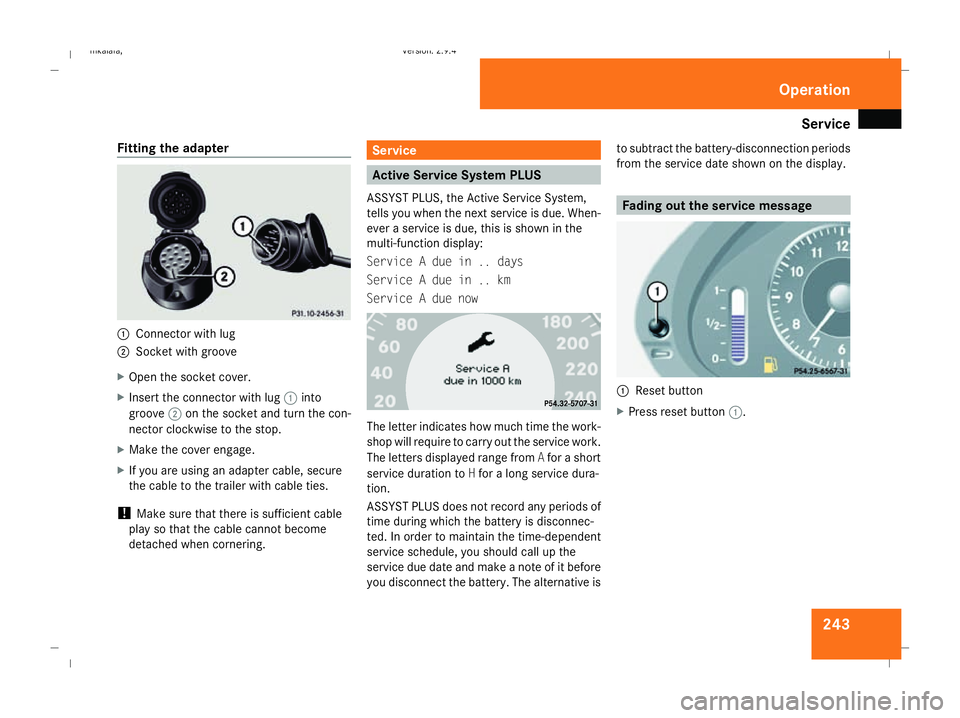
1
Connector with lug
2 Socket with groove
X Open the socket cover.
X Insert the connector with lug 1into
groove 2on the socket and turn the con-
nector clockwise to the stop.
X Make the cover engage.
X If you are using an adapter cable, secure
the cable to the trailer with cable ties.
! Make sure that there is sufficient cable
play so that the cable cannot become
detached when cornering. Service
Active Service System PLUS
ASSYST PLUS, the Active Service System,
tells you when the next service is due. When-
ever a service is due, this is shown in the
multi-function display:
Service A due in .. days
Service A due in .. km
Service A due now The letter indicates how much time the work-
shop will require to carry out the service work.
The letters displayed range from
Afor a short
service duration to Hfor a long service dura-
tion.
ASSYST PLUS does not record any periods of
time during which the battery is disconnec-
ted. In order to maintain the time-dependent
service schedule, you should call up the
service due date and make a note of it before
you disconnect the battery. The alternative is to subtract the battery-disconnection periods
from the service date shown on the display. Fading out the service message
1
Reset button
X Press reset button 1. Operation
211_AKB; 2; 5, en-GB
mkalafa,
Version: 2.9.4
2008-02-29T16:57:07+01:00 - Seite 243 ZDateiname: 6515_3416_02_buchblock.pdf; preflight
Page 257 of 401
Where will I find...?
254 Vehicle tool kit, jack and spare
wheel*
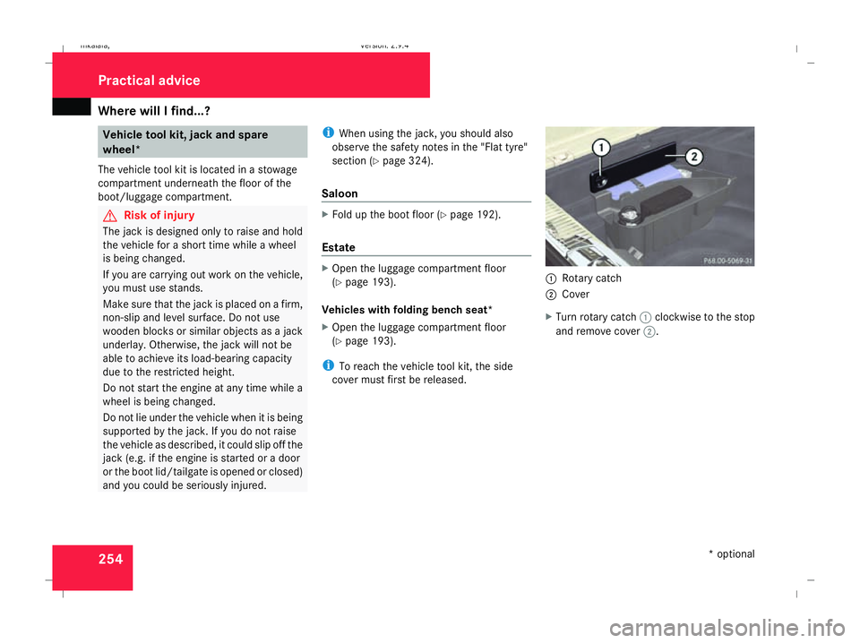
The vehicle tool kit is located in a stowage
compartment underneath the floor of the
boot/luggage compartment. G
Risk of injury
The jack is designed only to raise and hold
the vehicle for a short time while a wheel
is being changed.
If you are carrying out work on the vehicle,
you must use stands.
Make sure that the jack is placed on a firm,
non-slip and level surface. Do not use
wooden blocks or similar objects as a jack
underlay. Otherwise, the jack will not be
able to achieve its load-bearing capacity
due to the restricted height.
Do not start the engine at any time while a
wheel is being changed.
Do not lie under the vehicle when it is being
supported by the jack. If you do not raise
the vehicle as described, it could slip off the
jack (e.g. if the engine is started or a door
or the boot lid/tailgate is opened or closed)
and you could be seriously injured. i
When using the jack, you should also
observe the safety notes in the "Flat tyre"
section (Y page 324).
Saloon X
Fold up the boot floor (Y page 192).
Estate X
Open the luggage compartment floor
(Y page 193).
Vehicles with folding bench seat*
X Open the luggage compartment floor
(Y page 193).
i To reach the vehicle tool kit, the side
cover must first be released. 1
Rotary catch
2 Cover
X Turn rotary catch 1clockwise to the stop
and remove cover 2. Practical advice
* optional
211_AKB; 2; 5, en-GB
mkalafa,
Version: 2.9.4 2008-02-29T16:57:07+01:00 - Seite 254Dateiname: 6515_3416_02_buchblock.pdf; preflight
Page 259 of 401
Where will I find...?
256
Removing the "Minispare" emergency
spare wheel*/collapsible emergency
spare wheel or spare wheel*
X Saloon: remove the luggage well
(Y page 256).
X Estate: remove the luggage compartment
floor (Y page 194).
X Turn fastening element 3anti-clockwise.
X Remove the "Minispare" emergency spare
wheel/collapsible emergency spare wheel
or the spare wheel 2.
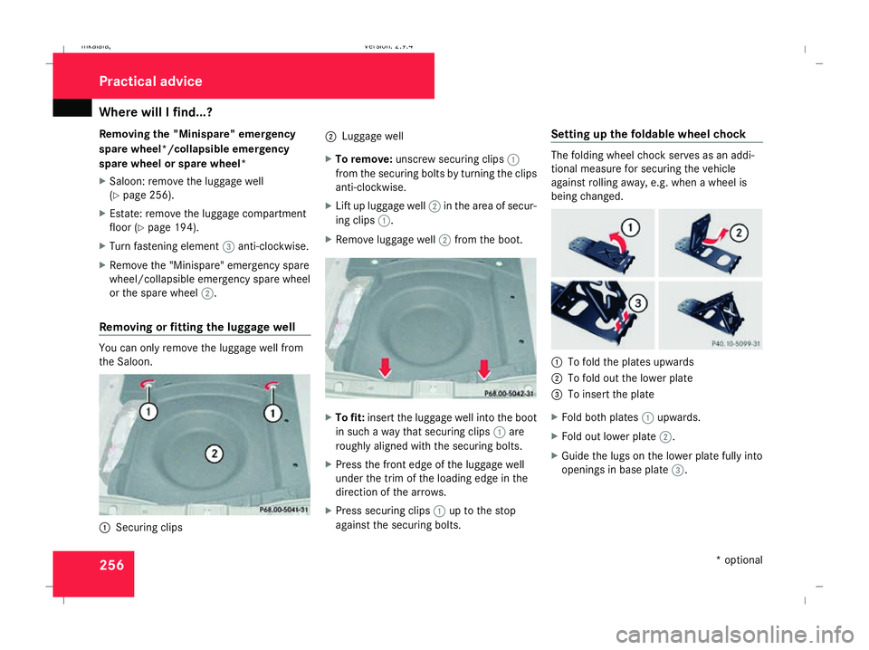
Removing or fitting the luggage well You can only remove the luggage well from
the Saloon. 1
Securing clips 2
Luggage well
X To remove: unscrew securing clips 1
from the securing bolts by turning the clips
anti-clockwise.
X Lift up luggage well 2in the area of secur-
ing clips 1.
X Remove luggage well 2from the boot. X
To fit: insert the luggage well into the boot
in such a way that securing clips 1are
roughly aligned with the securing bolts.
X Press the front edge of the luggage well
under the trim of the loading edge in the
direction of the arrows.
X Press securing clips 1up to the stop
against the securing bolts. Setting up the foldable wheel chock The folding wheel chock serves as an addi-
tional measure for securing the vehicle
against rolling away, e.g. when a wheel is
being changed.
1
To fold the plates upwards
2 To fold out the lower plate
3 To insert the plate
X Fold both plates 1upwards.
X Fold out lower plate 2.
X Guide the lugs on the lower plate fully into
openings in base plate 3.Practical advice
* optional
211_AKB; 2; 5, en-GB
mkalafa,
Version: 2.9.4 2008-02-29T16:57:07+01:00 - Seite 256Dateiname: 6515_3416_02_buchblock.pdf; preflight
Page 309 of 401
Locking/unlocking in an emergency
306 Locking/unlocking in an emergency
Emergency key
If the vehicle can no longer be unlocked or
locked with the key or the KEYLESS GO
key*, use the emergency key element.
If you use the emergency key element to
unlock and open the driver's door or the boot
lid (Saloon), the anti-theft alarm system* will
be triggered (Y page 62).
There are several ways to turn off the alarm:
X Press the korj button on the key.
or
X Insert the key into the ignition lock.
or
X Press the KEYLESS GO button* on the
selector lever. The KEYLESS GO key* must
be in the vehicle.
or
X Lock or unlock the vehicle using KEYLESS
GO*. The KEYLESS GO key* must be out-
side the vehicle. Releasing and removing the emergency
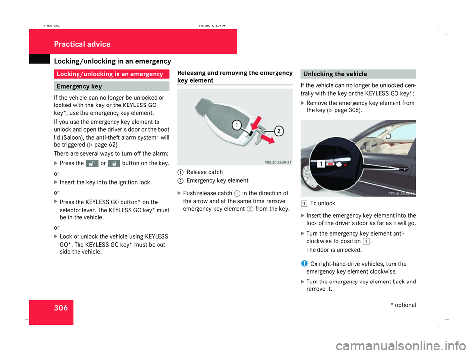
key element 1
Release catch
2 Emergency key element
X Push release catch 1in the direction of
the arrow and at the same time remove
emergency key element 2from the key. Unlocking the vehicle
If the vehicle can no longer be unlocked cen-
trally with the key or the KEYLESS GO key*:
X Remove the emergency key element from
the key (Y page 306). $
To unlock
X Insert the emergency key element into the
lock of the driver's door as far as it will go.
X Turn the emergency key element anti-
clockwise to position $.
The door is unlocked.
i On right-hand-drive vehicles, turn the
emergency key element clockwise.
X Turn the emergency key element back and
remove it. Practical advice
* optional
211_AKB; 2; 5, en-GB
mkalafa,
Version: 2.9.4 2008-02-29T16:57:07+01:00 - Seite 306Dateiname: 6515_3416_02_buchblock.pdf; preflight
Page 310 of 401
Locking/unlocking in an emergency
307Locking the vehicle
If the vehicle can no longer be locked cen-
trally with the key or the KEYLESS GO key*:
X Open the driver's door.
X Close the front-passenger door, the rear
doors and the boot lid/tailgate.
X Press the locking button (Y page 70).
X Check whether the locking knobs on the
doors are still visible. Press the locking
knobs down manually if necessary.
X Close the driver's door.
X Remove the emergency key element from
the key (Y page 306). $
To lock X
Insert the emergency key element into the
lock of the driver's door as far as it will go.
X Turn the emergency key element clockwise
as far as it will go to position $.
i On right-hand-drive vehicles, turn the
emergency key element anti-clockwise.
X Turn the emergency key element back and
remove it.
X Check whether the doors and the boot lid/
tailgate are locked. Opening/closing the boot
To unlock the boot !
The boot lid swings upwards when
opened. Therefore, make sure that there is
enough space above the boot lid.
If the boot can no longer be unlocked with the
key or the KEYLESS GO key*:
X Remove the emergency key element from
the key (Y page 306). Boot lock
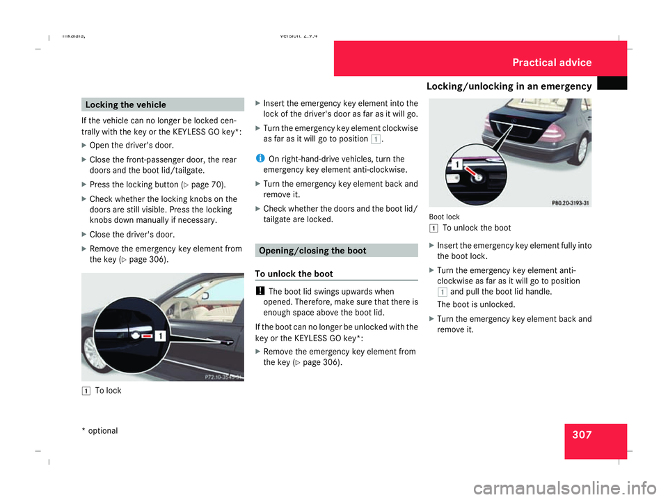
$
To unlock the boot
X Insert the emergency key element fully into
the boot lock.
X Turn the emergency key element anti-
clockwise as far as it will go to position
$ and pull the boot lid handle.
The boot is unlocked.
X Turn the emergency key element back and
remove it. Practical advice
* optional
211_AKB; 2; 5, en-GB
mkalafa,
Version: 2.9.4 2008-02-29T16:57:07+01:00 - Seite 307 ZDateiname: 6515_3416_02_buchblock.pdf; preflight
Page 317 of 401
Changing the bulbs
314 Changing the front bulbs
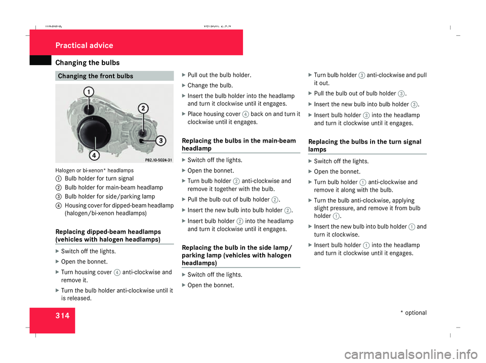
Halogen or bi-xenon* headlamps
1
Bulb holder for turn signal
2 Bulb holder for main-beam headlamp
3 Bulb holder for side/parking lamp
4 Housing cover for dipped-beam headlamp
(halogen/bi-xenon headlamps)
Replacing dipped-beam headlamps
(vehicles with halogen headlamps) X
Switch off the lights.
X Open the bonnet.
X Turn housing cover 4anti-clockwise and
remove it.
X Turn the bulb holder anti-clockwise until it
is released. X
Pull out the bulb holder.
X Change the bulb.
X Insert the bulb holder into the headlamp
and turn it clockwise until it engages.
X Place housing cover 4back on and turn it
clockwise until it engages.
Replacing the bulbs in the main-beam
headlamp X
Switch off the lights.
X Open the bonnet.
X Turn bulb holder 2anti-clockwise and
remove it together with the bulb.
X Pull the bulb out of bulb holder 2.
X Insert the new bulb into bulb holder 2.
X Insert bulb holder 2into the headlamp
and turn it clockwise until it engages.
Replacing the bulb in the side lamp/
parking lamp (vehicles with halogen
headlamps) X
Switch off the lights.
X Open the bonnet. X
Turn bulb holder 3anti-clockwise and pull
it out.
X Pull the bulb out of bulb holder 3.
X Insert the new bulb into bulb holder 3.
X Insert bulb holder 3into the headlamp
and turn it clockwise until it engages.
Replacing the bulbs in the turn signal
lamps X
Switch off the lights.
X Open the bonnet.
X Turn bulb holder 1anti-clockwise and
remove it along with the bulb.
X Turn the bulb anti-clockwise, applying
slight pressure, and remove it from bulb
holder 1.
X Insert the new bulb into bulb holder 1and
turn it clockwise.
X Insert bulb holder 1into the headlamp
and turn it clockwise until it engages. Practical advice
* optional
211_AKB; 2; 5, en-GB
mkalafa,
Version: 2.9.4 2008-02-29T16:57:07+01:00 - Seite 314Dateiname: 6515_3416_02_buchblock.pdf; preflight
Page 330 of 401
Flat tyre
327
X
Screw union nut 5on air hose 4onto the
valve.
X Insert plug 3into the cigarette lighter
socket* ( Ypage 209) or into a 12V socket
in your vehicle (Y page 210).
X Make sure that the key is in position 2in
the ignition lock.
X Press on/off switch 2on the electric air
pump to I.
The electric air pump is switched on. The
tyre is inflated.
X When a tyre pressure of 3.5 bar has been
reached, press 0on the electric air pump
switch.
The electric air pump is switched off.
! Do not operate the electric air pump for
longer than six minutes without a break.
Otherwise, it may overheat.
The air pump can be operated again once
it has cooled down.
If the tyre pressure is higher than 3.5 bar: X
Open the pressure release screw on the
pressure gauge until the tyre pressure is
correct.
X Disconnect the electric air pump and stow
it away.
Lowering the vehicle X
Lower the vehicle. To do this, turn the crank
of the jack anti-clockwise until the vehicle
is standing firmly on the ground again.
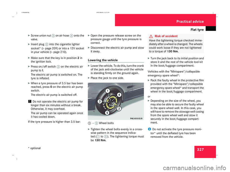
X Place the jack to one side. 1
–5 Wheel bolts
X Tighten the wheel bolts evenly in a cross-
wise pattern in the sequence indica-
ted ( 1to5). The tightening torque must
be 130 Nm . G
Risk of accident
Have the tightening torque checked imme-
diately after a wheel is changed. The wheels
could work loose if they are not tightened
to a torque of 130 Nm.
X Turn the jack back to its initial position and
store it and the rest of the vehicle tool kit
in the boot/luggage compartment.
Vehicles with the "Minispare"/collapsible
emergency spare wheel*:
X Pack the faulty wheel in the protective film
provided with the "Minispare"/collapsible
emergency spare wheel* and transport the
wheel in the boot/luggage compartment.
or
X Depending on the size of the wheel, you
may also be able to secure the faulty wheel
in the spare wheel well. In this case, you
will have to remove the stowage well casing
from the spare wheel well and stow it
securely in the boot/luggage compart-
ment.
i Do not activate the tyre pressure moni-
tor* until the deflated tyre has been
removed from the vehicle. Practical advice
* optional
211_AKB; 2; 5, en-GB
mkalafa,
Version: 2.9.4 2008-02-29T16:57:07+01:00 - Seite 327 ZDateiname: 6515_3416_02_buchblock.pdf; preflight
Page 341 of 401
Towing and tow-starting
338-
you cannot switch on the ignition
- you cannot move the selector lever
to N(on vehicles with automatic trans-
mission*)
- you have no support when braking
i Switch off the automatic locking feature
before the vehicle is towed (Y page 137).
You could otherwise be locked out when
pushing or towing the vehicle. Fitting the towing eye
Opening the front cover The mountings for the removable towing eyes
are located in the bumpers. They are located
at the front and rear under the covers on the right-hand side of the vehicle when viewed in
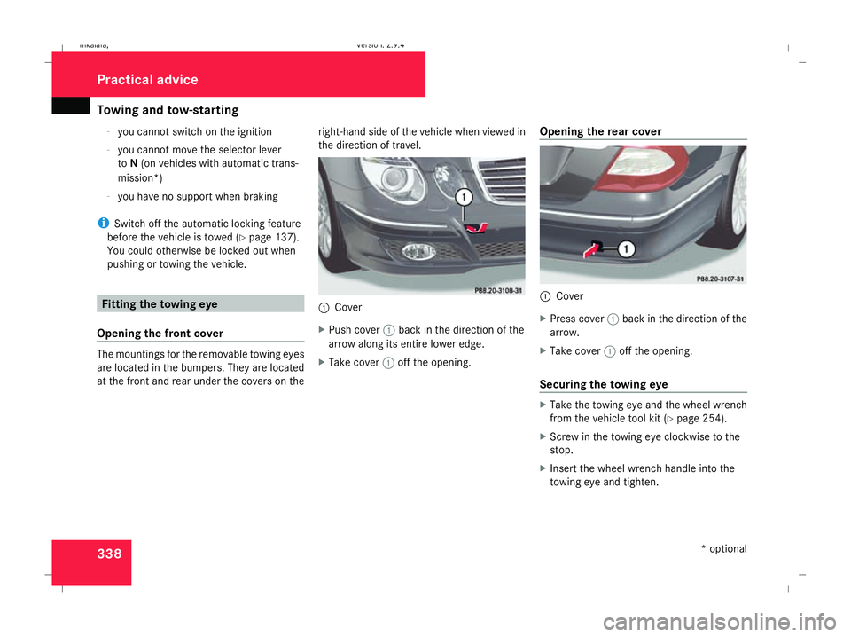
the direction of travel. 1
Cover
X Push cover 1back in the direction of the
arrow along its entire lower edge.
X Take cover 1off the opening. Opening the rear cover 1
Cover
X Press cover 1back in the direction of the
arrow.
X Take cover 1off the opening.
Securing the towing eye X
Take the towing eye and the wheel wrench
from the vehicle tool kit ( Ypage 254).
X Screw in the towing eye clockwise to the
stop.
X Insert the wheel wrench handle into the
towing eye and tighten. Practical advice
* optional
211_AKB; 2; 5, en-GB
mkalafa
,V ersion: 2.9.4
2008-02-29T16:57:07+01:00 - Seite 338 Dateiname: 6515_3416_02_buchblock.pdf; preflight
Page 342 of 401
Towing and tow-starting
339Towing the vehicle
! You may tow the vehicle for a maximum
of 50 km. A towing speed of 50 km/h must
not be exceeded.
With towing distances over 50 km, the
entire vehicle needs to be lifted up and
transported.
! Vehicles with 4MATIC* may not be towed
with the front or rear axle raised.
! The engine must be switched off (key in
ignition lock in position 0or position 1) if
the vehicle is being towed with the rear axle
raised or if the parking brake is being tested
on a dynamometer. Intervention by ESP ®
could otherwise damage the brake system.
Vehicles with manual transmission X
Turn the key to position 2in the ignition
lock.
X Shift to neutral. Vehicles with automatic transmission* X
Turn the key to position 2in the ignition
lock.
X Move the selector lever to N. Tow-starting (emergency engine
starting)
Please note:
R Vehicles with an automatic transmission*
must not be tow-started.
R The battery must be connected.
R The engine and catalytic converter must be
cold.
R Avoid repeated and lengthy starting
attempts.
Vehicles with manual transmission X
Turn the key to position 2in the ignition
lock.
X Fully depress the clutch pedal.
X Shift to neutral. X
Tow the vehicle or let it roll.
X Shift to a suitable gear and bring the clutch
pedal up slowly. Do not depress the accel-
erator pedal.
The engine is started. Removing the towing eye
X Take the wheel wrench from the vehicle
tool kit ( Ypage 254).
X Insert the wheel wrench handle into the
towing eye and turn it anti-clockwise.
X Unscrew the towing eye.
X Replace the cover and press it until it
engages.
X Return the towing eye and the wheel
wrench to the vehicle tool kit. Practical advice
* optional
211_AKB; 2; 5, en-GB
mkalafa
,V ersion: 2.9.4
2008-02-29T16:57:07+01:00 - Seite 339 ZDateiname: 6515_3416_02_buchblock.pdf; preflight
Page 344 of 401
Fuses
341Main fuse box
The main fuse box is located on the driver's
side of the dashboard. 1
Main fuse box cover
2 Flat, blunt object
! Do not use a pointed object, such as a
screwdriver, to open the fuse box in the
dashboard. You could otherwise damage
the dashboard.
X To open: open the driver’s door.
X Insert a flat, blunt object into the recess as
a lever 2. X
Remove cover 1from the dashboard
using a flat, blunt object 2.
X Pull cover 1in the direction of the arrow
by hand and remove it.
X To close: clip in cover 1at the front.
X Fold cover 1inwards until it engages.
X Close the driver's door. Fuse box in the boot or luggage com-
partment
Saloon The fuse box is located in the boot behind the
trim on the left-hand side when viewed in the
direction of travel.
1
Catches
2 Cover
X To open: open the boot lid.
X Turn both catches 1anti-clockwise.
X Remove cover 2.
X To close: insert and engage cover 2.
X Close the boot lid. Practical advice
211_AKB; 2; 5, en-GB
mkalafa,
Version: 2.9.4 2008-02-29T16:57:07+01:00 - Seite 341 ZDateiname: 6515_3416_02_buchblock.pdf; preflight