phone MERCEDES-BENZ E-CLASS ESTATE 2012 Owner's Manual
[x] Cancel search | Manufacturer: MERCEDES-BENZ, Model Year: 2012, Model line: E-CLASS ESTATE, Model: MERCEDES-BENZ E-CLASS ESTATE 2012Pages: 457, PDF Size: 11.62 MB
Page 337 of 457
led bracket (see the separate mobile phone
bracket fitting instructions).
Vehicles with automatic transmission
with DIRECT SELECT lever:
install the
sliding adapter depending on the model of
the mobile phone bracket (Y page 335).
X Insert the mobile phone into the mobile
phone bracket (see the separate installa-
tion instructions for the mobile phone fit-
ting).
i On some mobile phone brackets, you first
have to connec tthe mobile phone via Blue-
tooth ®
to the mobile phone bracket (see
the separate operating instructions for the
mobile phone bracket).
If this is the case, the mobile phone does
not have to be inserted into the bracket for
you to be able to use the telephone func-
tions. However, the charging function and
aerial function are not available.
Operating the mobile phone You can operate the telephone using the
6
and~ buttons on the multifunction
steering wheel. You can operate other mobile
phone functions via the on-board computer
(Y page 254).
When you remove the key from the ignition
lock, the mobile phone stays switched on.
However, you can no longer use the hands-
free system.
If you have an active call and would like to
take the key out of the ignition lock, first
remove the mobile phone from the bracket.
i When using a bracket connected to the
mobile phone via Bluetooth ®
and you wish
to proceed with a call:
Switch to private mode before removing
the key from the ignition lock. Otherwise, it
may take up to 20 seconds, before the
mobile phone separates from the system.
Only then can the telephone call continue.
Information on the necessary steps for set-
ting up "private mode" can be found in the separate mobile phone operating instruc-
tions.
i Not all mobile phones support "private
mode".
Mobile telephone bracket in the stow-
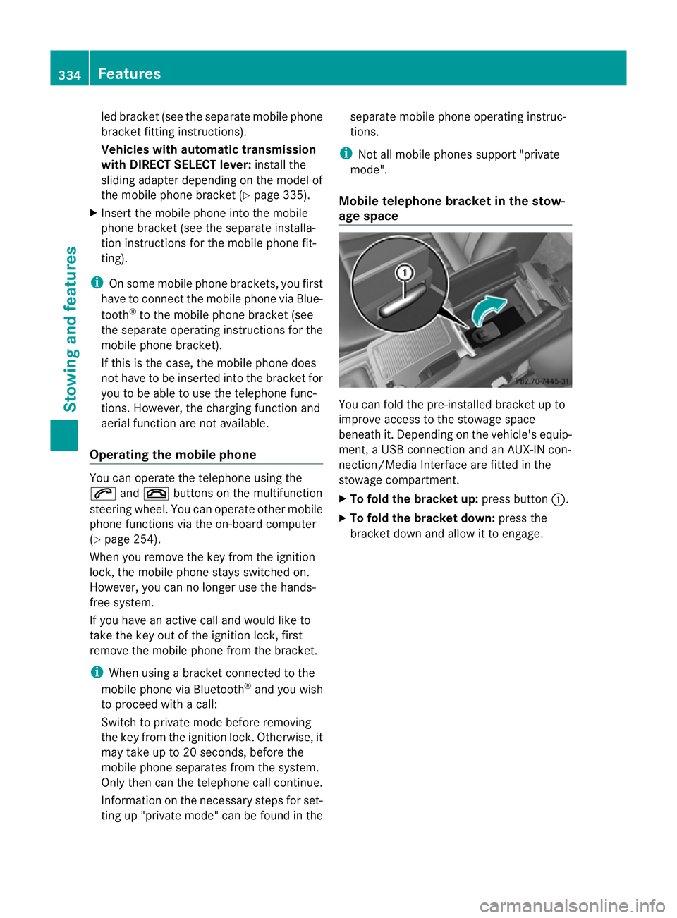
age space You can fold the pre-installed bracket up to
improve access to the stowage space
beneath it. Depending on the vehicle's equip-
ment, a USB connection and an AUX-IN con-
nection/Media Interface are fitted in the
stowage compartment.
X
To fold the bracket up: press button:.
X To fold the bracket down: press the
bracket down and allow it to engage. 334
FeaturesStowing and features
Page 338 of 457
Sliding adapter for the mobile phone
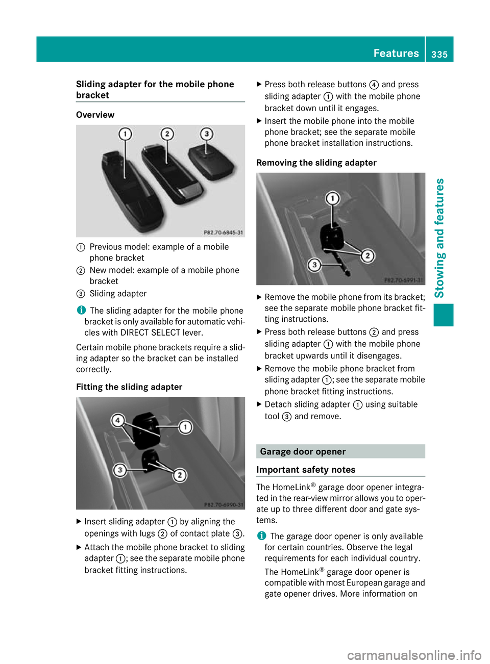
bracket Overview
:
Previous model: example of a mobile
phone bracket
; New model: example of a mobile phone
bracket
= Sliding adapter
i The sliding adapter for the mobile phone
bracket is only available for automatic vehi-
cles with DIRECT SELECT lever.
Certain mobile phone brackets require a slid-
ing adapter so the bracket can be installed
correctly.
Fitting the sliding adapter X
Insert sliding adapter :by aligning the
openings with lugs ;of contact plate =.
X Attach the mobile phone bracket to sliding
adapter :; see the separate mobile phone
bracket fitting instructions. X
Press both release buttons ?and press
sliding adapter :with the mobile phone
bracket down until it engages.
X Insert the mobile phone into the mobile
phone bracket; see the separate mobile
phone bracket installation instructions.
Removing the sliding adapter X
Remove the mobile phone from its bracket;
see the separate mobile phone bracket fit-
ting instructions.
X Press both release buttons ;and press
sliding adapter :with the mobile phone
bracket upwards until it disengages.
X Remove the mobile phone bracket from
sliding adapter :; see the separate mobile
phone bracket fitting instructions.
X Detach sliding adapter :using suitable
tool =and remove. Garage door opener
Important safety notes The HomeLink
®
garage door opener integra-
ted in the rear-view mirror allows you to oper-
ate up to three different door and gate sys-
tems.
i The garage door opener is only available
for certain countries. Observe the legal
requirements for each individual country.
The HomeLink ®
garage door opener is
compatible with most European garage and
gate opener drives. More information on Features
335Stowing and features Z
Page 344 of 457
Asia
Country Radio type approval num-
ber
Frequency range (MHz)
AE (United
Arab Emi-
rates) 1623/5/10-2/26/76
MHz: 433
JO (Jordan) TRC/LPD/2005/23
MHz: 27, 30, 40
,433, 868 KW (Kuwait) 5 October 2005
MHz: 27, 30, 40, 418, 433,
868
LB (Leba-
non) 2920/O&M/2006 / 3 July
05
MHz: 27, 40, 433, 868
SA (Saudi
Arabia) 11_02_05/5024-5-6
MHz: 418, 433
SY (Syria) 279/4/14 / 05 March 06
TR (Turkey) National Certification 23
July 07
MHz: 433
Australia
Country Radio type approval num-
ber
Frequency range (MHz)
AU (Aus-
tralia) 28 June
MHz: 27, 30, 40, 433, 868
NZ (New
Zealand) 20 March 06
MHz: 27, 30, 40, 433
Floormat on the driver's side
G
WARNING
Make sure that there is sufficient clearance
around the pedals whe nfloormats are used,
and that the floormats are properly secured. The floormats must be correctly secured at all
times using the securing knob and retainers.
Before you drive off, chec
kthe floormats and
secure them if necessary. Afloormat which is
not properly secured can slip and thereby
interfere with the movemen tofthe pedals.
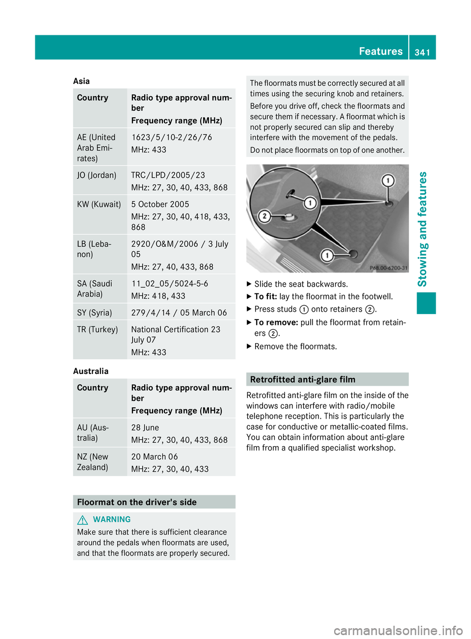
Do not place floormats on top of one another. X
Slide the seat backwards.
X To fit: lay the floormat in the footwell.
X Press studs :onto retainers ;.
X To remove: pull the floormat from retain-
ers ;.
X Remove the floormats. Retrofitted anti-glare film
Retrofitted anti-glare film on the inside of the
windows can interfere with radio/mobile
telephone reception. This is particularly the
case for conductive or metallic-coated films.
You can obtain information about anti-glare
film from a qualified specialist workshop. Features
341Stowing and features Z
Page 350 of 457
When checking the oil level:
R
park the vehicle on a level surface.
R the engine should be switched off for
approximately five minutes if the engine is
at normal operating temperature.
R if the engine is not at normal operating
temperature, e.g. if the engine was only
started briefly: wait about 30 minutes
before carrying out the measurement.
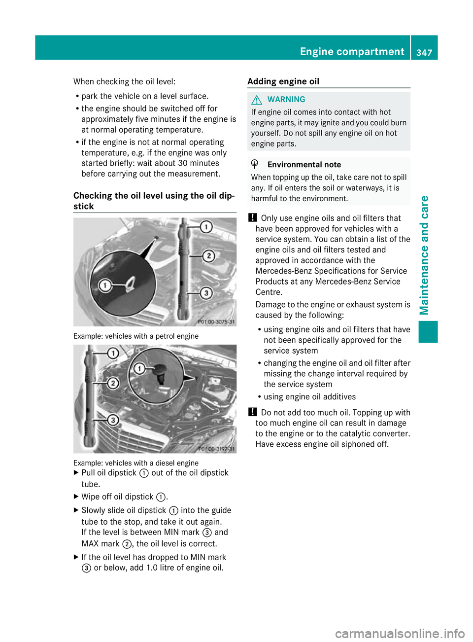
Checking the oil level using the oil dip-
stick Example: vehicles with a petrol engine
Example: vehicles with a diesel engine
X
Pull oil dipstick :out of the oil dipstick
tube.
X Wipe off oil dipstick :.
X Slowly slide oil dipstick :into the guide
tube to the stop, and take it out again.
If the level is between MIN mark =and
MAX mark ;, the oil level is correct.
X If the oil level has dropped to MIN mark
= or below, add 1.0 litre of engine oil. Adding engine oil G
WARNING
If engine oil comes into contact with hot
engine parts, it may ignite and you could burn
yourself. Do not spill any engine oil on hot
engine parts. H
Environmental note
When topping up the oil, take care not to spill
any. If oil enters the soil or waterways, it is
harmful to the environment.
! Only use engine oils and oil filters that
have been approved for vehicles with a
service system. You can obtain a list of the
engine oils and oil filters tested and
approved in accordance with the
Mercedes-Benz Specifications for Service
Products at any Mercedes-Benz Service
Centre.
Damage to the engine or exhaust system is
caused by the following:
R using engine oils and oil filters that have
not been specifically approved for the
service system
R changing the engine oil and oil filter after
missing the change interval required by
the service system
R using engine oil additives
! Do not add too much oil. Topping up with
too much engine oil can result in damage
to the engine or to the catalytic converter.
Have excess engine oil siphoned off. Engine compartment
347Maintenance and care Z
Page 353 of 457

Information abou
tService Resetting the ASSYST PLUS service inter-
val display
!
If the ASSYST PLUS service interval dis-
play has been inadvertently reset, this set-
ting can be corrected at a qualified special-
ist workshop.
Have service work carried out as described
in the Service Booklet. This may otherwise
lead to increased wear and damage to the
major assemblies or the vehicle.
Aq ualified specialist workshop, e.g. a
Mercedes-Ben zService Centre, will reset the
ASSYST PLUS service interval display after
the service work has been carried out. You
can also obtain further information on main-
tenance work, for example.
Special service requirements
Arduous operating conditions or increased
loads on the vehicle will require some service
work to be performed more often than for a
vehicle in normal use. Such arduous condi-
tions include regular city driving with frequent
intermediate stops and use in mountainous
terrain or on poor road surfaces.
For example, if the vehicle is used under ardu-
ous operating conditions, have air filters,
engine oil and oil filters changed frequently
and chec kthe wheels often.F urther informa-
tion can be obtained at a qualified specialist
workshop, e.g. a Mercedes-Ben zService
Centre.
Driving abroad
An extensive Mercedes-Benz Service network
is also available in other countries. The
Service Hotline's curren ttelephone numbers
for use when you are abroad are to be found
in the "Mercedes-Benz Service24h" section
of the Service Booklet. AdBlue
®
service indicator
i For BlueTEC vehicles only. To function properly, BlueTEC exhaust gas
aftertreatment must be operated with the
reducing agent AdBlue
®
. AdBlue ®
is topped
up as part of the service. Under normal oper-
ating conditions, a full tank of AdBlue ®
should
last until the nexts ervice due date.
Depending on how and where the vehicle is
used, there may be an increase in the
AdBlue ®
consumption, resulting in the next
service due date being brought forward.
Certain display messages show that
AdBlue ®
must be topped up, e.g.
Refill AdBlue at workshop See Own‐ er's Manual
Refill AdBlue at workshop No start
in .. km
Aw
arning tone also sounds.
You can no longer start the engine when the
AdBlue ®
supply has been used up
(Y page 281).
! Have the AdBlue ®
tank topped up at a
qualified specialist workshop only. The
vehicle may otherwise be damaged or
soiled.
Before taking a trip with your vehicle outside
Europe, have the AdBlue ®
supply checked at
a qualified specialist workshop. If necessary,
have AdBlue ®
topped up. Before a longer stay
outside of Europe, consult a qualified special-
ist workshop.
Observe the notes on AdBlue ®
(Y page 440).
You can obtain further informatio nabout
BlueTEC exhaust gas aftertreatment and
AdBlue ®
from any Mercedes-Benz Service
Centre. Care
General notes
H
Environmental note
Dispose of empty packaging and cleaning
cloths in an environmentally responsible man-
ner. 350
CareMaintenance and care
Page 370 of 457
X
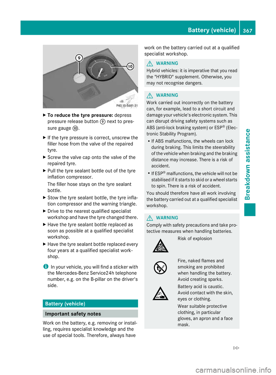
To reduce the tyre pressure: depress
pressure release button Enext to pres-
sure gauge F.
X If the tyre pressure is correct, unscrew the
fille rhose from the valve of the repaired
tyre.
X Screw the valve cap onto the valve of the
repaired tyre.
X Pull the tyre sealant bottle out of the tyre
inflation compressor.
The filler hose stays on the tyre sealant
bottle.
X Stow the tyre sealant bottle, the tyre infla-
tion compressor and the warning triangle.
X Drive to the nearest qualified specialist
workshop and have the tyre changed there.
X Have the tyre sealant bottle replaced as
soon as possible at a qualified specialist
workshop.
X Have the tyre sealant bottle replaced every
four years at a qualified specialist work-
shop.
i In your vehicle, you will find a sticker with
the Mercedes-Benz Service24h telephone
number, e.g. on the B-pillar on the driver's
side. Battery (vehicle)
Important safety notes
Work on the battery, e.g. removing or instal-
ling, requires specialist knowledge and the
use of special tools. Therefore, always have work on the battery carried out at a qualified
specialist workshop. G
WARNING
Hybrid vehicles: it is imperative that you read
the "HYBRID" supplement. Otherwise, you
may not recognise dangers. G
WARNING
Work carried out incorrectly on the battery
can, for example, lead to a short circuit and
damage your vehicle's electronic system. This
can disrupt driving safety systems such as
ABS (anti-lock braking system) or ESP ®
(Elec-
tronic Stability Program).
R If ABS malfunctions, the wheels can lock
during braking. This limits the steerability
of the vehicle when braking and the braking
distance may increase. There is a risk of
accident.
R If ESP ®
malfunctions, the vehicle will not be
stabilised if it starts to skid or a wheel starts
to spin. There is a risk of accident.
You should therefore have all work involving
the battery carried out at a qualified specialist
workshop. G
WARNING
Comply with safety precautions and take pro-
tective measures when handling batteries. Risk of explosion
Fire, naked flames and
smoking are prohibited
when handling the battery.
Avoid creating sparks.
Battery acid is caustic.
Avoid contact with the skin,
eyes or clothing.
Wear suitable protective
clothing, in particular
gloves, an apron and a face
mask. Battery (vehicle)
367Breakdown assistance
Z
Page 389 of 457
If you wish to confirm the restart:
X
Press button a.
The Tyre press. now OK? message
appears in the multifunction display.
X Press the 9or: buttonto select
Yes .
X Press the abutton.
The Run Flat Indicator restarted message appears in the multifunction dis-
play.
After a teach-in period, the tyre pressure
loss warning system will monitor the set
tyre pressures of all four tyres.
If you wish to cancel the restart:
X Press button %.
or
X When the Tyre press. now OK? message
appears, press the 9or: button to
select Cancel .
X Press the abutton.
The tyre pressure values stored at the last
restart will continue to be monitored. Tyre pressure monitor
Important safety notes It is the driver's responsibility to set the tyre
pressure to the recommended cold tyre pres-
sure suitable for the operating situation
(Y
page 383). Note that the correc ttyre pres-
sure fo rthe current operating situation must
first be taught-in to the tyre pressure monitor.
If there is a substantial loss of pressure, the
warning threshold for the warning message is
aligned to the reference values taught-in.
Restart the tyre pressure monitor after
adjusting to the cold tyre pressure
(Y page 387). The current pressures are
saved as new reference values. This will
ensure that a warning message will only
appearift he tyre pressure drops significantly.
The tyre pressure monitor does not warn you
of an incorrectly set tyre pressure. Observe the notes on the recommended tyre pressure
(Y
page 383).
The tyre pressure monitor is not able to warn
you of a sudden loss of pressure, e.g. if the
tyre is penetrated by a foreign object. In the
event of a sudden loss of pressure, bring the
vehicle to a halt by braking carefully. Avoid
abrupt steering manoeuvres.
If a tyre pressure monitor system is fitted, the
vehicle's wheels have sensors fitted that
monitor the tyre pressures in all four tyres.
The tyre pressure monitor warns you if the
pressure drops in one or more of the tyres.
The tyre pressure monitor only functions if
the corresponding sensors are fitted to all
wheels.
Information on tyre pressures is displayed in
the multifunction display. After a few minutes
of driving, the current tyre pressure of each
tyre is shown in the multifunction display.
The tyre pressure values indicated by the on-
board computer may differ from those meas-
ured at a filling station using a pressure
gauge. The tyre pressures shown by the on-
board computer refer to those measured at
sea level. At high altitudes, the tyre pressure
values indicated by a pressure gauge are
higher than those shown by the on-board
computer. In this case, do not reduce the tyre
pressures.
The operation of the tyre pressure monitor
can be affected by interference from radio
transmitting equipment (e.g. radio head-
phones, two-way radios) that may be being
operated in or near the vehicle.
Checking tyre pressure electronically X
Make sure that the key is in position
2(Y page 161) in the ignition lock.
X Press the =or; button on the steer-
ing wheel to select the Serv. menu.386
Tyre pressureWheels and tyres
Page 436 of 457
This is the case:
R
if they cause a change of the vehicle type
from that for which the vehicle's general
operating permit was granted
R if other road users could be endangered
R if the emission or noise levels are adversely
affected.
Always specify the vehicle identification num-
ber (VIN) (Y page 435) and the engine num-
ber (Y page 435) when ordering genuine
Mercedes-Benz parts. Vehicle electronics
Tampering with the engine electron-
ics
G
WARNING
Always have work on the engine electronics
and related components carried out at a quali-
fied specialist workshop. Otherwise, the vehi-
cle's operating safety could be affected.
! Only have work carried out on the engine
electronics and its associated parts, such
as control units, sensors and connector
leads, at a qualified specialist workshop.
Vehicle components may otherwise wear
more quickly and the vehicle's operating
permit may be invalidated. Retrofitting two-way radios and
mobile phones (RF transmitters)
G
WARNING
Incorrect retrofitting of RF transmitters can
cause the vehicle electronics to malfunction.
The vehicle's operating safety and thus your
own safety are impaired.
Have aftermarket radio frequency transmit-
ting equipment installed at a qualified spe-
cialist workshop. G
WARNING
Incorrect retrofitting of RF transmitters can
lead to increased electromagnetic radiation in
the vehicle interior. Using an exterior aerial
takes into account current scientific discus-
sions relating to the possible health hazards
that may result from electromagnetic fields.
Have aftermarket radio frequency transmit-
ting equipment installed at a qualified spe-
cialist workshop.
! The operating permit may be invalidated
if the instructions for installation and use of
RF transmitters are not observed.
In particular, the following conditions must
be complied with:
R only approved wavebands may be used.
R the maximum permissible output in
these wavebands must be complied with.
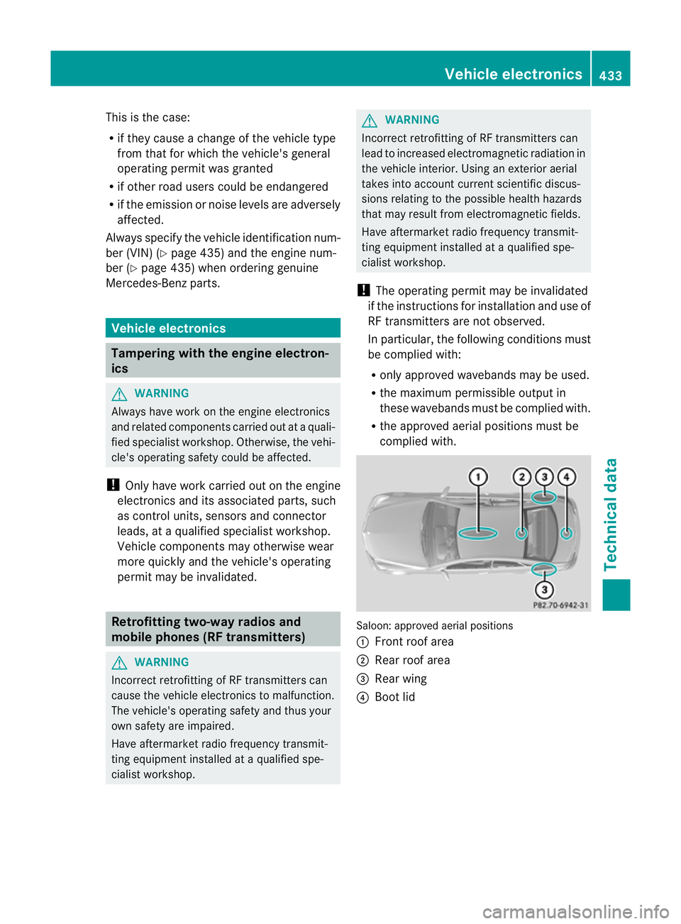
R the approved aerial positions must be
complied with. Saloon: approved aerial positions
:
Front roof area
; Rear roof area
= Rear wing
? Boot lid Vehicle electronics
433Technical data Z
Page 437 of 457
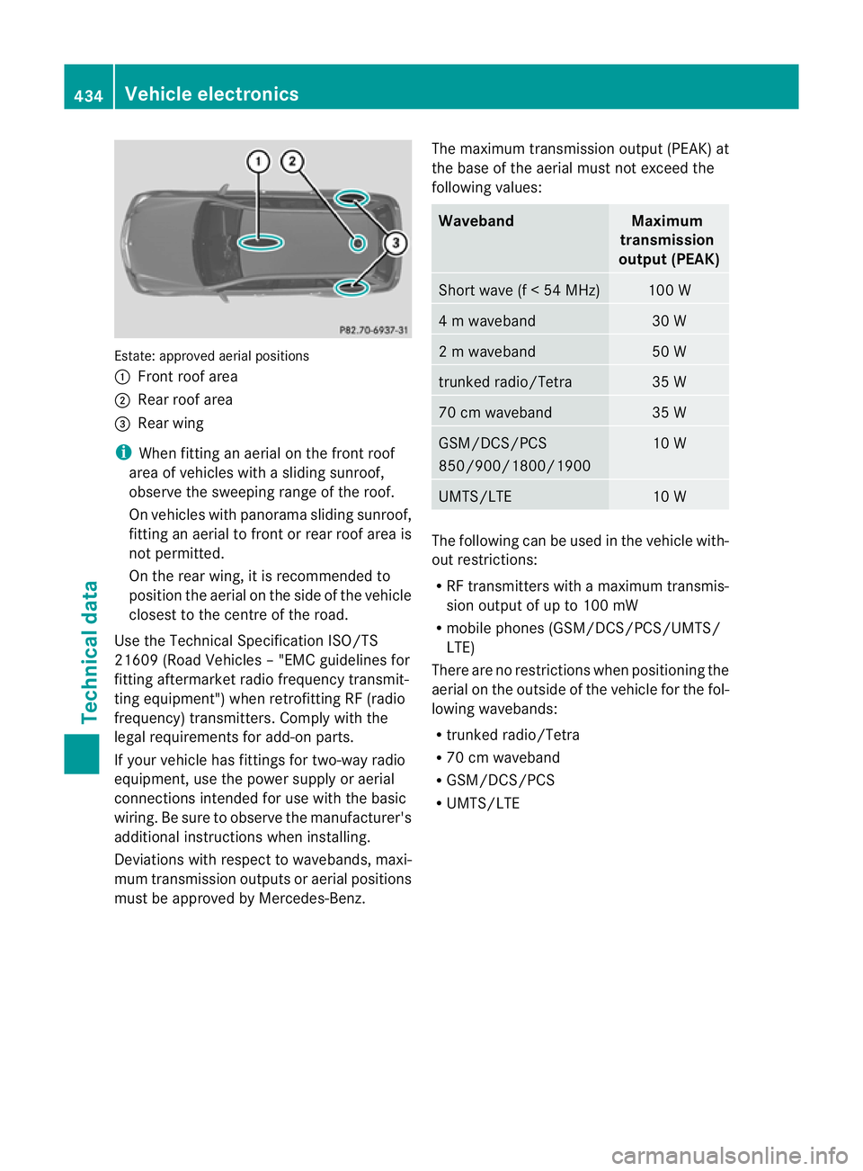
Estate: approved aerial positions
:
Front roof area
; Rear roo farea
= Rearw ing
i When fitting an aerial on the front roof
area of vehicles with a sliding sunroof,
observe the sweeping range of the roof.
On vehicles with panorama sliding sunroof,
fitting an aerial to front or rear roof area is
not permitted.
On the rear wing, it is recommended to
position the aerial on the side of the vehicle
closest to the centre of the road.
Use the Technical Specification ISO/TS
21609 (Road Vehicles –"EMC guidelines for
fitting aftermarket radio frequency transmit-
ting equipment") when retrofitting RF (radio
frequency) transmitters .Comply with the
legal requirements for add-on parts.
If your vehicle has fittings for two-way radio
equipment, use the power supply or aerial
connections intended for use with the basic
wiring. Be sure to observe the manufacturer's
additional instructions when installing.
Deviations with respect to wavebands, maxi-
mum transmission outputs or aerial positions
must be approved by Mercedes-Benz. The maximum transmission output (PEAK) at
the base of the aerial must not exceed the
following values: Waveband Maximum
transmission
output( PEAK) Short wave (f < 54 MHz) 100 W
4 m waveband 30 W
2 m waveband 50 W
trunked radio/Tetra 35 W
70 cm waveband 35 W
GSM/DCS/PCS
850/900/1800/1900 10 W
UMTS/LTE 10 W
The following can be used in the vehicle with-
out restrictions:
R
RF transmitters with amaximum transmis-
sion output of up to 100 mW
R mobile phones (GSM/DCS/PCS/UMTS/
LTE)
There are no restriction swhen positioning the
aerial on the outside of the vehicle for the fol-
lowing wavebands:
R trunked radio/Tetra
R 70 cm waveband
R GSM/DCS/PCS
R UMTS/LTE 434
Vehicle electronicsTechnical data