key MERCEDES-BENZ E-CLASS SALOON 2008 Owners Manual
[x] Cancel search | Manufacturer: MERCEDES-BENZ, Model Year: 2008, Model line: E-CLASS SALOON, Model: MERCEDES-BENZ E-CLASS SALOON 2008Pages: 401, PDF Size: 6.89 MB
Page 320 of 401
Flat tyre
317
X
Remove the key from the ignition lock.
X Fold the wiper arm away from the rear win-
dow until it engages.
X Turn wiper blade 1at a right angle to wiper
arm.
X Press tab 2and push wiper blade 1off
the retainer in the direction of arrow 4.
X Remove wiper blade 1.
Fitting X
Insert the new wiper blade into retainer
3 in the opposite direction to arrow 4
until tab 2engages.
X Make sure that wiper blade 1is seated
correctly.
X Turn wiper blade 1parallel to the wiper
arm.
X Fold the wiper arm back onto the rear win-
dow. Flat tyre
Your vehicle may be equipped with:
R a TIREFIT kit (Y page 255)
R a "Minispare" emergency spare
wheel* (Y page 255)
R a collapsible emergency spare
wheel* (Y page 255)
R a spare wheel* (Y page 255)
R the MOExtended run-flat sys-
tem* (Y page 328) Preparing the vehicle
i Vehicle preparation is not necessary on
vehicles with MOE tyres*.
X Stop your vehicle as far away from traffic
as possible on solid, non-slippery, level
ground.
X Switch on the hazard warning lamps.
X Firmly depress the parking brake.
Vehicles with manual transmission X
Shift to either first or reverse gear. Vehicles with automatic transmission* X
Move the selector lever to P.
For all vehicles X
All occupants must get out of the vehicle.
Make sure that they are not endangered as
they do so.
X Make sure that no one is near the danger
area whilst a wheel is being changed. Any-
one who is not directly assisting in the
wheel change should, for example, stand
behind the barrier.
X Switch off the engine.
X Remove the key from the ignition lock.
X Place the warning triangle ( Ypage 252) or
warning lamps at a suitable distance.
Observe legal requirements. G
Risk of injury
The jack is designed only to raise the vehi-
cle for a short time while a wheel is being
changed.
If you intend to work under the vehicle, it
must be placed on stands. Practical advice
* optional
211_AKB; 2; 5, en-GB
mkalafa,
Version: 2.9.4
2008-02-29T16:57:07+01:00 - Seite 317 ZDateiname: 6515_3416_02_buchblock.pdf; preflight
Page 323 of 401
Flat tyre
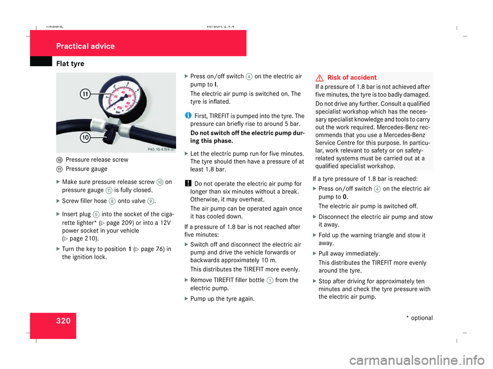
320a
Pressure release screw
b Pressure gauge
X Make sure pressure release screw aon
pressure gauge bis fully closed.
X Screw filler hose 8onto valve 9.
X Insert plug 5into the socket of the ciga-
rette lighter* (Y page 209) or into a 12V
power socket in your vehicle
(Y page 210).
X Turn the key to position 1(Y page 76) in
the ignition lock. X
Press on/off switch 4on the electric air
pump to I.
The electric air pump is switched on. The
tyre is inflated.
i First, TIREFIT is pumped into the tyre. The
pressure can briefly rise to around 5 bar.
Do not switch off the electric pump dur-
ing this phase.
X Let the electric pump run for five minutes.
The tyre should then have a pressure of at
least 1.8 bar.
! Do not operate the electric air pump for
longer than six minutes without a break.
Otherwise, it may overheat.
The air pump can be operated again once
it has cooled down.
If a pressure of 1.8 bar is not reached after
five minutes:
X Switch off and disconnect the electric air
pump and drive the vehicle forwards or
backwards approximately 10 m.
This distributes the TIREFIT more evenly.
X Remove TIREFIT filler bottle 1from the
electric pump.
X Pump up the tyre again. G
Risk of accident
If a pressure of 1.8 bar is not achieved after
five minutes, the tyre is too badly damaged.
Do not drive any further. Consult a qualified
specialist workshop which has the neces-
sary specialist knowledge and tools to carry
out the work required. Mercedes-Benz rec-
ommends that you use a Mercedes-Benz
Service Centre for this purpose. In particu-
lar, work relevant to safety or on safety-
related systems must be carried out at a
qualified specialist workshop.
If a tyre pressure of 1.8 bar is reached:
X Press on/off switch 4on the electric air
pump to 0.
The electric air pump is switched off.
X Disconnect the electric air pump and stow
it away.
X Fold up the warning triangle and stow it
away.
X Pull away immediately.
This distributes the TIREFIT more evenly
around the tyre.
X Stop after driving for approximately ten
minutes and check the tyre pressure with
the electric air pump. Practical advice
* optional
211_AKB; 2; 5, en-GB
mkalafa,
Version: 2.9.4 2008-02-29T16:57:07+01:00 - Seite 320Dateiname: 6515_3416_02_buchblock.pdf; preflight
Page 325 of 401
Flat tyre
3227
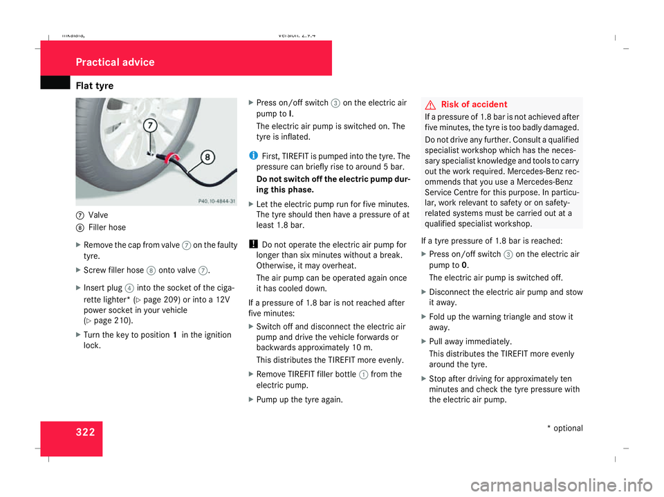
Valve
8 Filler hose
X Remove the cap from valve 7on the faulty
tyre.
X Screw filler hose 8onto valve 7.
X Insert plug 4into the socket of the ciga-
rette lighter* (Y page 209) or into a 12V
power socket in your vehicle
(Y page 210).
X Turn the key to position 1in the ignition
lock. X
Press on/off switch 3on the electric air
pump to I.
The electric air pump is switched on. The
tyre is inflated.
i First, TIREFIT is pumped into the tyre. The
pressure can briefly rise to around 5 bar.
Do not switch off the electric pump dur-
ing this phase.
X Let the electric pump run for five minutes.
The tyre should then have a pressure of at
least 1.8 bar.
! Do not operate the electric air pump for
longer than six minutes without a break.
Otherwise, it may overheat.
The air pump can be operated again once
it has cooled down.
If a pressure of 1.8 bar is not reached after
five minutes:
X Switch off and disconnect the electric air
pump and drive the vehicle forwards or
backwards approximately 10 m.
This distributes the TIREFIT more evenly.
X Remove TIREFIT filler bottle 1from the
electric pump.
X Pump up the tyre again. G
Risk of accident
If a pressure of 1.8 bar is not achieved after
five minutes, the tyre is too badly damaged.
Do not drive any further. Consult a qualified
specialist workshop which has the neces-
sary specialist knowledge and tools to carry
out the work required. Mercedes-Benz rec-
ommends that you use a Mercedes-Benz
Service Centre for this purpose. In particu-
lar, work relevant to safety or on safety-
related systems must be carried out at a
qualified specialist workshop.
If a tyre pressure of 1.8 bar is reached:
X Press on/off switch 3on the electric air
pump to 0.
The electric air pump is switched off.
X Disconnect the electric air pump and stow
it away.
X Fold up the warning triangle and stow it
away.
X Pull away immediately.
This distributes the TIREFIT more evenly
around the tyre.
X Stop after driving for approximately ten
minutes and check the tyre pressure with
the electric air pump. Practical advice
* optional
211_AKB; 2; 5, en-GB
mkalafa,
Version: 2.9.4 2008-02-29T16:57:07+01:00 - Seite 322Dateiname: 6515_3416_02_buchblock.pdf; preflight
Page 330 of 401
Flat tyre
327
X
Screw union nut 5on air hose 4onto the
valve.
X Insert plug 3into the cigarette lighter
socket* ( Ypage 209) or into a 12V socket
in your vehicle (Y page 210).
X Make sure that the key is in position 2in
the ignition lock.
X Press on/off switch 2on the electric air
pump to I.
The electric air pump is switched on. The
tyre is inflated.
X When a tyre pressure of 3.5 bar has been
reached, press 0on the electric air pump
switch.
The electric air pump is switched off.
! Do not operate the electric air pump for
longer than six minutes without a break.
Otherwise, it may overheat.
The air pump can be operated again once
it has cooled down.
If the tyre pressure is higher than 3.5 bar: X
Open the pressure release screw on the
pressure gauge until the tyre pressure is
correct.
X Disconnect the electric air pump and stow
it away.
Lowering the vehicle X
Lower the vehicle. To do this, turn the crank
of the jack anti-clockwise until the vehicle
is standing firmly on the ground again.
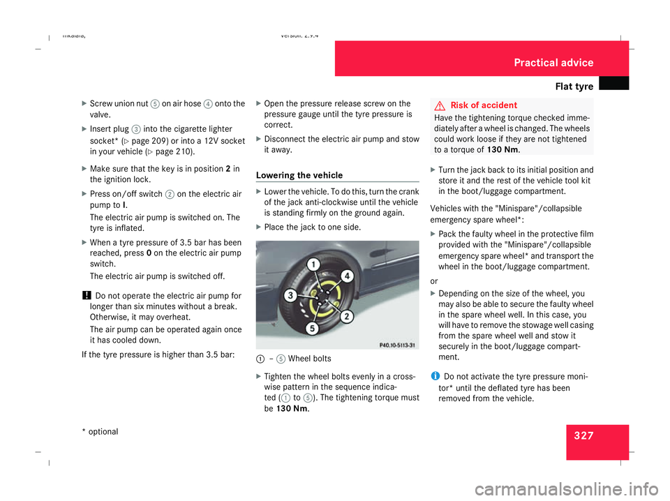
X Place the jack to one side. 1
–5 Wheel bolts
X Tighten the wheel bolts evenly in a cross-
wise pattern in the sequence indica-
ted ( 1to5). The tightening torque must
be 130 Nm . G
Risk of accident
Have the tightening torque checked imme-
diately after a wheel is changed. The wheels
could work loose if they are not tightened
to a torque of 130 Nm.
X Turn the jack back to its initial position and
store it and the rest of the vehicle tool kit
in the boot/luggage compartment.
Vehicles with the "Minispare"/collapsible
emergency spare wheel*:
X Pack the faulty wheel in the protective film
provided with the "Minispare"/collapsible
emergency spare wheel* and transport the
wheel in the boot/luggage compartment.
or
X Depending on the size of the wheel, you
may also be able to secure the faulty wheel
in the spare wheel well. In this case, you
will have to remove the stowage well casing
from the spare wheel well and stow it
securely in the boot/luggage compart-
ment.
i Do not activate the tyre pressure moni-
tor* until the deflated tyre has been
removed from the vehicle. Practical advice
* optional
211_AKB; 2; 5, en-GB
mkalafa,
Version: 2.9.4 2008-02-29T16:57:07+01:00 - Seite 327 ZDateiname: 6515_3416_02_buchblock.pdf; preflight
Page 333 of 401
Battery
330 step out of the vehicle first and touch the
bodywork.
R Do not wipe the battery using a cloth. The
battery may explode as a result of elec-
trostatic charge or due to flying sparks.
! Switch the engine off and remove the key
before unscrewing or disconnecting the
terminal clamps from the battery. You may
otherwise destroy electronic components
such as the alternator.
i Mercedes-Benz recommends that you
have all work involving the battery, e.g.
removing, charging and replacing, carried
out at a qualified specialist workshop, e.g.
a Mercedes-Benz Service Centre.
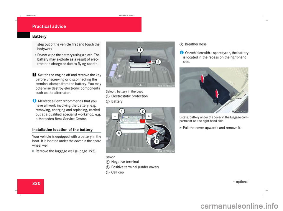
Installation location of the battery Your vehicle is equipped with a battery in the
boot. It is located under the cover in the spare
wheel well.
X Remove the luggage well (Y page 192). Saloon: battery in the boot
1
Electrostatic protection
2 Battery Saloon
1
Negative terminal
2 Positive terminal (under cover)
3 Cell cap 4
Breather hose
i On vehicles with a spare tyre*, the battery
is located in the recess on the right-hand
side. Estate: battery under the cover in the luggage com-
partment on the right-hand side
X
Pull the cover upwards and remove it. Practical advice
* optional
211_AKB; 2; 5, en-GB
mkalafa,
Version: 2.9.4 2008-02-29T16:57:07+01:00 - Seite 330Dateiname: 6515_3416_02_buchblock.pdf; preflight
Page 334 of 401
Battery
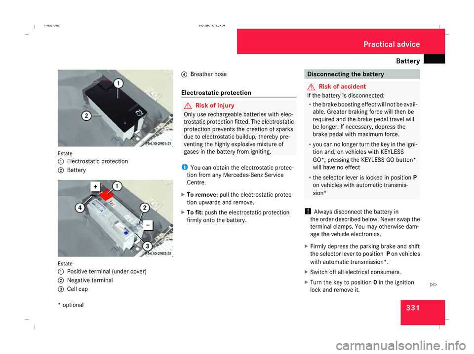
331Estate
1 Electrostatic protection
2 Battery Estate
1 Positive terminal (under cover)
2 Negative terminal
3 Cell cap 4
Breather hose
Electrostatic protection G
Risk of injury
Only use rechargeable batteries with elec-
trostatic protection fitted. The electrostatic
protection prevents the creation of sparks
due to electrostatic buildup, thereby pre-
venting the highly explosive mixture of
gases in the battery from igniting.
i You can obtain the electrostatic protec-
tion from any Mercedes-Benz Service
Centre.
X To remove: pull the electrostatic protec-
tion upwards and remove.
X To fit: push the electrostatic protection
firmly onto the battery. Disconnecting the battery
G
Risk of accident
If the battery is disconnected:
R the brake boosting effect will not be avail-
able. Greater braking force will then be
required and the brake pedal travel will
be longer. If necessary, depress the
brake pedal with maximum force.
R you can no longer turn the key in the igni-
tion and, on vehicles with KEYLESS
GO*, pressing the KEYLESS GO button*
will have no effect
R the selector lever is locked in position P
on vehicles with automatic transmis-
sion*
! Always disconnect the battery in
the order described below. Never swap the
terminal clamps. You may otherwise dam-
age the vehicle electronics.
X Firmly depress the parking brake and shift
the selector lever to position Pon vehicles
with automatic transmission*.
X Switch off all electrical consumers.
X Turn the key to position 0in the ignition
lock and remove it. Practical advice
* optional
211_AKB; 2; 5, en-GB
mkalafa
, Version: 2.9.4 2008-02-29T16:57:07+01:00 - Seite 331 ZDateiname: 6515_3416_02_buchblock.pdf; preflight
Page 340 of 401
Towing and tow-starting
337Towing and tow-starting
Points to remember
G
Risk of accident
If you tow the vehicle, you must use a rigid
towing bar if:
R the engine is not running
R there is a brake system malfunction
R the voltage supply or the vehicle's elec-
trical system is damaged
The electric power steering and the brake
force boosting effect do not work when the
engine is not running. Greater braking force
will then be required and the brake pedal
travel will be longer. If necessary, depress
the brake pedal with maximum force.
Do not tow the vehicle if the key cannot be
turned in the ignition lock. If this is the case,
the steering is locked and the vehicle can-
not be steered.
If you tow or tow-start another vehicle, its
weight must not exceed the maximum per-
missible gross vehicle weight of your vehi-
cle. G
Risk of accident
The vehicle is braked when HOLD is activa-
ted. Therefore, deactivate HOLD if the vehi-
cle is to be towed.
If you tow or tow-start another vehicle, its
weight must not exceed the maximum per-
missible gross vehicle weight of your vehi-
cle.
It is better to have the vehicle transported
than to have it towed.
When towing, observe the legal requirements
in all countries concerned.
! When towing, pull away slowly and with-
out jerking. If the tractive power is too high,
the vehicles could be damaged. Do not use
the towing eye for recovery.
! You may tow the vehicle for a maximum
of 50 km. A towing speed of 50 km/h must
not be exceeded.
With towing distances over 50 km, the
entire vehicle needs to be lifted up and
transported.
! Only secure the tow cable or towing bar
to the towing eyes. You may otherwise
damage the vehicle. R
Vehicles with an automatic transmission*
must not be tow-started.
R If the engine does not start, try jump start-
ing (Y page 333).
R If it is not possible to jump-start the vehicle,
have it towed to the nearest qualified spe-
cialist workshop, e.g. a Mercedes-Benz
Service Centre.
R If the vehicle has suffered transmission
damage, only tow it with the propeller shaft
disconnected.
R The automatic transmission* selector lever
must be in the Nposition when towing the
vehicle away.
R If you are towing the vehicle over a consid-
erable distance, this must only be done
with the rear axle raised.
R The ignition must be switched off if you are
towing the vehicle with the front/rear axle
raised. Intervention by ESP ®
could other-
wise damage the brake system.
R Vehicles with 4MATIC* may not be towed
with the front or rear axle raised.
R Before towing the vehicle, make sure that
the battery is connected and charged. Oth-
erwise: Practical advice
* optional
211_AKB; 2; 5, en-GB
mkalafa
,V ersion: 2.9.4
2008-02-29T16:57:07+01:00 - Seite 337 ZDateiname: 6515_3416_02_buchblock.pdf; preflight
Page 342 of 401
Towing and tow-starting
339Towing the vehicle
! You may tow the vehicle for a maximum
of 50 km. A towing speed of 50 km/h must
not be exceeded.
With towing distances over 50 km, the
entire vehicle needs to be lifted up and
transported.
! Vehicles with 4MATIC* may not be towed
with the front or rear axle raised.
! The engine must be switched off (key in
ignition lock in position 0or position 1) if
the vehicle is being towed with the rear axle
raised or if the parking brake is being tested
on a dynamometer. Intervention by ESP ®
could otherwise damage the brake system.
Vehicles with manual transmission X
Turn the key to position 2in the ignition
lock.
X Shift to neutral. Vehicles with automatic transmission* X
Turn the key to position 2in the ignition
lock.
X Move the selector lever to N. Tow-starting (emergency engine
starting)
Please note:
R Vehicles with an automatic transmission*
must not be tow-started.
R The battery must be connected.
R The engine and catalytic converter must be
cold.
R Avoid repeated and lengthy starting
attempts.
Vehicles with manual transmission X
Turn the key to position 2in the ignition
lock.
X Fully depress the clutch pedal.
X Shift to neutral. X
Tow the vehicle or let it roll.
X Shift to a suitable gear and bring the clutch
pedal up slowly. Do not depress the accel-
erator pedal.
The engine is started. Removing the towing eye
X Take the wheel wrench from the vehicle
tool kit ( Ypage 254).
X Insert the wheel wrench handle into the
towing eye and turn it anti-clockwise.
X Unscrew the towing eye.
X Replace the cover and press it until it
engages.
X Return the towing eye and the wheel
wrench to the vehicle tool kit. Practical advice
* optional
211_AKB; 2; 5, en-GB
mkalafa
,V ersion: 2.9.4
2008-02-29T16:57:07+01:00 - Seite 339 ZDateiname: 6515_3416_02_buchblock.pdf; preflight
Page 343 of 401
Fuses
340 Transporting the vehicle
The towing eyes can be used to pull the vehi-
cle onto a trailer or transporter for transport-
ing purposes.
! Only lash the vehicle down by the wheels
or wheel rims, not by parts of the vehicle
such as axle or steering components. The
vehicle could otherwise be damaged.
Vehicles with manual transmission X
Shift to neutral.
Vehicles with automatic transmission* X
Turn the key to position 2in the ignition
lock.
X Move the selector lever to N. Fuses
Notes on changing fuses
The fuses in your vehicle serve to close down
faulty circuits. If a fuse blows, all the compo-
nents on the circuit and their functions will
fail.
Blown fuses must be replaced with fuses of
the same rating, which you can recognise by
the colour and value. The fuse ratings are lis-
ted in the fuse allocation chart. A Mercedes-
Benz Service Centre will be happy to advise
you. G
Risk of fire
Only use fuses that have been approved for
Mercedes-Benz vehicles and which have
the correct fuse rating for the systems con-
cerned. Do not attempt to repair or bridge
faulty fuses. Otherwise, a circuit overload
could cause a fire. Have the cause traced
and rectified at a qualified specialist work-
shop, e.g. a Mercedes-Benz Service Centre.
If the newly inserted fuse also blows, have the
cause traced and rectified at a qualified spe-
cialist workshop, e.g. a Mercedes-Benz
Service Centre. !
Only use fuses that have been approved
for Mercedes-Benz vehicles and which
have the correct fuse rating for the system
concerned. Otherwise, components or sys-
tems could be damaged.
The fuses are located in various fuse boxes:
R Main fuse box on the driver's side of the
dashboard
R Fuse box in the boot/luggage compart-
ment on the left-hand side of the vehicle
Fuse allocation chart The fuse allocation chart is in the main fuse
box in the dashboard.
Before changing a fuse
X Park the vehicle.
X Switch off all electrical consumers.
X Remove the key from the ignition lock. Practical advice
* optional
211_AKB; 2; 5, en-GB
mkalafa,
Version: 2.9.4 2008-02-29T16:57:07+01:00 - Seite 340Dateiname: 6515_3416_02_buchblock.pdf; preflight