change time MERCEDES-BENZ E-CLASS SALOON 2015 Owner's Manual
[x] Cancel search | Manufacturer: MERCEDES-BENZ, Model Year: 2015, Model line: E-CLASS SALOON, Model: MERCEDES-BENZ E-CLASS SALOON 2015Pages: 497, PDF Size: 16.23 MB
Page 267 of 497
rear and side of yourv
ehicleare alsom oni-
tored with the aid of the rada rsensor system.
Active Lane Keeping Assist detects lane
markings on the road and can warn you
before you leave yourl ane unintentionally.If
you do not react to the warning, alane-cor-
recting application of the brakes can bring the
vehicl eback into the original lane.
This function is available withi naspeedrange
between 60 km/h and 200 km/h.
For Active Lane Keeping Assist to assist you
when driving, the rada rsensor system must
be operational.
Important safety notes
If you fail to adapt yourd riving style,Active
Lane Keeping Assist can neither reduce the
risk of an accident nor overrid ethe lawsof
physics. Active Lane Keeping Assist cannot
take account of road and weather conditions.
It may not detect traffic situations. Active
Lane Keeping Assist is only an aid.Y ou are
responsible for the distance to the vehicl ein
front, for vehicl espeed, for braking in good
time, and for staying in lane.
Active Lane Keeping Assist cannot continu-
ousl ykeep yourv ehicleini ts lane. G
WARNING
Active Lane Keeping Assist cannot always
clearly detect lane markings.
In such cases, Active Lane Keeping Assist
can:
R give an unnecessary warning and then
make acourse-correcting brake application
to the vehicle
R neither give awarning nor intervene
There is arisk of an accident.
Always pay particular attention to the traffic
situation and keep withi nthe lane, especially
if Active Lane Keeping Assist alerts you.T er-
minate the intervention in anon-critical driv-
ing situation. The system may be impaired or may not func-
tion if:
R there is poor visibility, e.g. due to insuffi-
cient illumination of the road ,ordue to
snow, rain, fog or spray
R there is glare, e.g. from oncoming traffic,
the sun or reflectio nfrom other vehicles
(e.g. if the road surface is wet)
R the windscreen is dirty ,misted up, dam-
agedorc overed, for instance by asticker,
in the vicinity of the camera
R the rada rsensors in the front or rear bump-
ers or the radiator trim are dirty ,e.g.
obscured by snow
R no or several, unclea rlane markings are
present for one lane, e.g. in aconstruction
area
R the lane markings are worn away,d ark or
covered up, e.g. by dirt or snow
R the distance to the vehicl einfront is too
smal land the lane markings thus cannot be
detected
R the lane markings change quickly, e.g.
lanes branch off, cross one another or
merge
R the road is narrow and winding
R there are highly variable shad econditions
on the road
If no vehicl eisdetected in the adjacent lane
and broken lane markings are detected, no
lane-correcting brake application is made.
Warning vibratio nthrough the steering
wheel
Aw arning may be given if afront wheel
passes over alane marking. It willw arny ou by
means of intermittent vibration in the steer-
ing whee lfor up to 1.5 seconds.
Lane-correcting brake application G
WARNING
Al ane-correcting brake application cannot
alwaysb ring the vehicl eback into the original
lane. There is arisk of an accident. 264
Driving systemsDriving and parking
Page 271 of 497
The maximum permissible speed for vehicle/
trailer combinations depends on the type of
trailer. Before beginnin gthe journey, check
the trailer's document stosee what the max-
imum permitted speed is. Observe the legally
prescribed maximum speed in the relevant
country.
For certain Mercedes-Benz vehicles, the max-
imum permissible rear axle load is increased
when towing atrailer. See the "Technical
data" section to find out whether this applies to your vehicle (Y page 484). If you utilise any
of the added maximum rear axle load when
towing atrailer, the vehicle/trailer combina-
tion may not exceed amaximum speed of
100 km/hf or reasons concerning the oper-
ating permit. This also applie sincountrie sin
which the permissible maximu mspee dfor
vehicle/trailer combinations is above
100 km/h.
When towing atrailer, you rvehicle's handling
characteristics wil lbedifferent in comparison
to whe ndriving without atrailer and it will
consume more fuel.
Change into alower gea ringood time on long
and steep downhill gradients.
i This also applie
sifyou have activated
cruis econtrol, SPEEDTRONIC or
DISTRONIC PLUS.
This wil luse the braking effect of the engine,
so less braking wil lberequired to maintain
vehicle speed. This relieves the loa donthe
brake system and prevents the brake sfrom
overheating and wearing too quickly. If you
need additiona lbraking, depress the brake
pedal repeatedl yrather than continuously.
Driving tips If the trailer swings from side to side:
X Do not accelerate.
X Do not countersteer.
X Brake if necessary. R
Maintain agreater distance to the vehicle in
front than whe ndriving without atrailer.
R Avoid braking abruptly .Ifpossible ,brake
gently at first to allow the trailer to run on.
Then, increase the braking force rapidly.
R The values give nfor gradient-climbing
capabilities from astandstil lrefer to sea
level. When driving in mountainous areas,
note that the power outpu tofthe engine,
and consequently the vehicle's gradient-
climbing capability, decrease with increas-
ing altitude. Foldin
gout the ball coupling G
WARNING
If the bal lcoupling is not correctly engaged,
the trailer can detach .There is arisk of an
accident.
Always engag ethe bal lcoupling as described. G
WARNING
If you release the bal lcoupling or it does not
engag ecorrectly whe nfolding in, it wil lswing
out. Withi npivoting range of the bal lcoupling,
there is an increased risk of an accident and
injury.
Only release the bal lcoupling if the pivoting
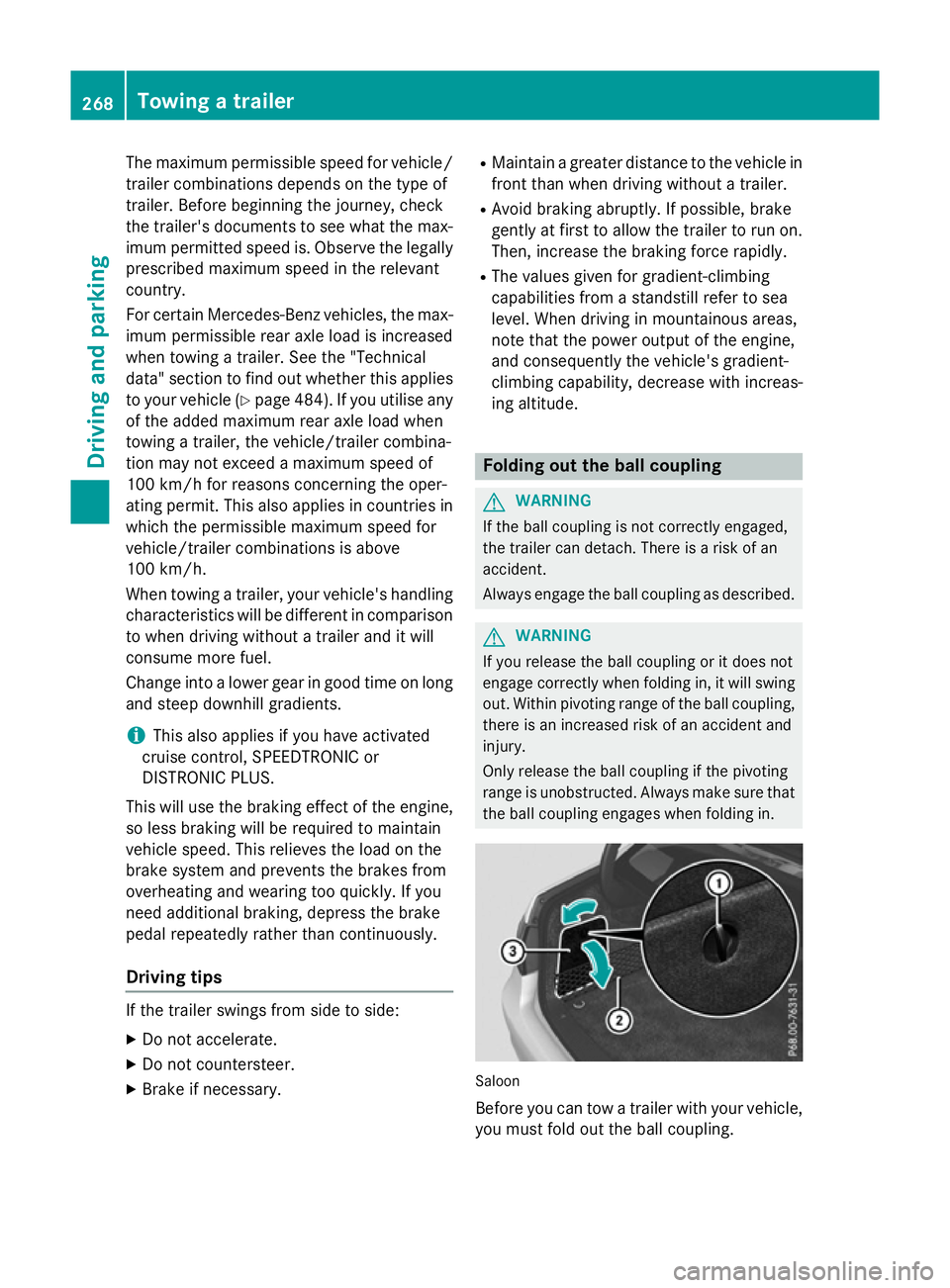
range is unobstructed. Always make sure that the bal lcoupling engages whe nfolding in. Saloon
Before you can tow
atrailer with you rvehicle,
you must fold out the bal lcoupling. 268
Towing
atrailerDriving and parking
Page 294 of 497
X
Press the :or9 button to select the
Intell. Light Sys.
Intell. Light Sys. function.
If the Intell. Light Sys.
Intell. Light Sys. function has
been switched on, the cone of light and the L symbol in the multifunction display
are shown in orange.
X Press the abutton to save the setting.
When you switch the Intell. Light Sys.
Intell. Light Sys.
function on, you activat ethe following func-
tions:
R Motorway mode
R Active light function
R Cornerin glight function
R Extended range foglamps
If you set the dipped-beam headlamps for
driving on the right/left, the multifunction
display shows the Intell.
Intell. Light LightSystem:
System:
System inoperative Inactive for
System inoperative Inactive for
left-side traffic left-side traffic orIntell. Light
Intell. Light
System:
System: System
Systeminoperative
inoperative Inactive
Inactive
for right-sid etraffic
for right-sid etraffic display message
instead of the Intell.
Intell. Light
LightSys.
Sys.function
in the Light
Light submenu (Y page 291). This
display message will only appear if the setting for driving on the left/right is set opposite to
your vehicle's country version.
Observe the additional information on the
Intelligent Light System (Y page 145).
Setting the dipped-beam headlamps for
driving on the left/right
This function is only availabl eonvehicles with
the Intelligent Light System.
You can use this function to switch between
symmetrical and asymmetrical dipped beam
(Y page 142).
X Press the =or; button on the steer-
ing wheel to select the Settings
Settings menu.
X Press the :or9 button to select the
Light
Light submenu.
X Press ato confirm. X
Press the :or9 button to select the
Dipped beams Setting for: Dipped beams Setting for: function.
You will see the selected setting: Right-
Right-
side traffic
side traffic orLeft-side traffic
Left-side traffic.
X Press the abutton to save the setting.
If you change the setting, conversion does
not take place until the next time the vehi-
cle is stationary.
If you set the dipped-beam headlamps for
driving on the right/left, then motorway
mode and the extended range foglamps are
unavailable. These are only deactivated if the
setting for driving on the left/right is set
opposite to your vehicle's country version.
Aq ualified specialist workshop can set the
dipped-beam headlamps for driving on the
left/right.
Setting the brightness of the ambient
lighting
X Press the =or; button on the steer-
ing wheel to select the Settings
Settings menu.
X Press the :or9 button to select the
Lights Lights submenu.
X Press ato confirm.
X Press the :or9 button to select the
Amb. light +/-
Amb. light +/- function.
You will see the selected setting.
X Press ato confirm.
X Press the :or9 button to adjust the
brightness to any level from Off
OfftoLevel 5
Level 5
(bright).
X Press the aor% button to save the
setting.
Setting the ambient lighting colour X Press the =or; button on the steer-
ing wheel to select the Settings
Settingsmenu.
X Press the :or9 button to select the
Lights
Lights submenu.
X Press ato confirm.
X Press the :or9 button to select the
Amb. light col.
Amb. light col. function.
X Press ato confirm. Menus and submenus
291On-board computer and displays Z
Page 297 of 497
In the
Heating
Heating submenu, you can select a
stored departure time or change adeparture
time.
The auxiliary heating timer function calcu-
lates the switch-on time according to the out-
side temperature so that the vehicle is pre-
heated by the departure time. When the
departure time is reached ,the auxiliary heat-
ing continues to heat for afurther five
minutes and then switches off. The auxiliary
heating adopts the THERMATIC or
THERMOTRONIC temperature setting.
You can switch off the auxiliary heating by
using the remote control or the auxiliary heat- ing button on the centre console.
i Switch the auxiliary heating on regularly
once amonth for aboutt en minutes.
Further information on auxiliary heating
(Y page 168).
Selecting the departur etime or deactivat-
ing aselected departur etime
X Press the =or; button on the steer-
ing wheeltos elect theSettings
Settings menu.
X Press the :or9 button to select the
Heating
Heating submenu.
X Press ato confirm.
You wills ee the selected setting.
X Press ato confirm.
X Press the :or9 button to select
one of the three departure times or Timer Timer
off
off (no timer active).
X Press ato confirm.
If ad eparture time is selected, the yellow
indicator lamp lights up on the auxiliary
heating button.
Changing the departur etime
X Press the =or; button on the steer-
ing wheeltos elect theSettings Settings menu.
X Press the :or9 button to select the
Heating
Heating submenu.
X Press ato confirm.
You wills ee the selected setting. X
Press the :or9 button to select A A,B B
or Change C
Change C.
X Press ato confirm.
You can now change the departure time.
X Press the =or; button to select the
display to be changed: hours, minutes.
X Press the :or9 button to set the
selected display.
X Press the abutton to store the entry.
The yellow indicator lamp on the auxiliary
heating button lights up.
Comfort Activating/deactivating the EASY-
ENTRY/EXIT feature
G
WARNING
When the EASY-ENTRY/EXIT feature adjusts
the steering wheel, you and other vehicle
occupants –particularly childre n–could
become trapped .There is arisk of injury.
Whilet he EASY-ENTRY/EXIT feature is mak-
ing adjustments, make sure that no one has
any body parts in the sweep of the steering
wheel.
If someone is trapped:
R press one of the memory function position
buttons, or
R move the switch for steering wheela djust-
ment in the opposite direction to that in
which the steering wheelism oving.
The adjustment process is stopped.
X Press the =or; button on the steer-
ing wheeltos elect theSettings Settings menu.
X Press the :or9 button to select the
Convenience
Convenience submenu.
X Press ato confirm.
X Press the :or9 button to select the
Easy Entry/Exit:
Easy Entry/Exit: function.
If the Easy Entry/Exit
Easy Entry/Exit function is activa-
ted, the vehicle steering wheelisd isplayed
in orange in the multifunction display.
X Press the abutton to save the setting. 294
Menus and submenusOn-board computer and displays
Page 402 of 497
TIREFI
Tkit
Important safety notes TIREFIT is
atyres ealan t.
Yo uc an us eTIREFIT to seal punctures of up to
4m m, particularly thos einthe tyr etread. You
can us eTIREFIT at outside temperatures
down to Ò20 †. G
WARNING
In the following situations, the tyr esealant is
unabl etop rovidesufficient breakdow nassis-
tance ,asitisu nabletos ealthe tyr eproperly:
R there ar ecuts or punctures in the tyre
large rtha nt hos em entione dabove.
R the whee lrim is damaged.
R youh aved riven at ver ylow tyrep ressures
or on aflatt yre.
There is ariskofana ccident.
Do not drive any further. Contact aquali fied
specialis tworkshop. G
WARNING
The tyr esealant is harmfu land causes irrita-
tion. It must not come into contact with your
skin, eyes or clothing or be swallowed. Do not inhal eTIREFIT fumes .Keept yres ealant away
fro mc hildren. There is ariskofi njury.
If yo ucome into contact with the tyr esealant,
observe the following:
R Rinse off the tyr esealant fro myours kin
immediatel ywithw ater.
R If the tyr esealant come sinto contact with
your eyes, immediatel yrinse the mthor-
oughl ywithc lean water.
R If tyr esealant is swallowed, immediately
rinse your mouth ou tthoroughl yand drink
plenty of water. Do not induce vomiting,
and see kmedica lattentio nimmediately.
R Immediately change ou tofclothing which
ha sc ome into contact with tyr esealant.
R If an allergi creactio noccurs, see kmedical
attentio nimmediately. !
Do not operate the tyr
einflation com-
presso rfor longe rtha ne ight minute sata
time withou tabreak. It ma yotherwise
overheat.
The tyr einflation compressor can be oper-
ate dagain once it ha scoole ddown.
Compl ywitht he manufacturer's safety
instructions on the sticker on the tyr einfla-
tio nc ompressor.
Usin gthe TIREFI Tkit X
Do not remove any foreign objects which
have penetrated the tyre, e.g .screws or
nails.
X Remov ethe tyr esealan tbottle ,the accom-
panying TIREFIT sticker and the tyr einfla-
tio nc ompressor fro mthe stowag espace
under the boot floor/luggage compart-
ment floor (Y page 395).
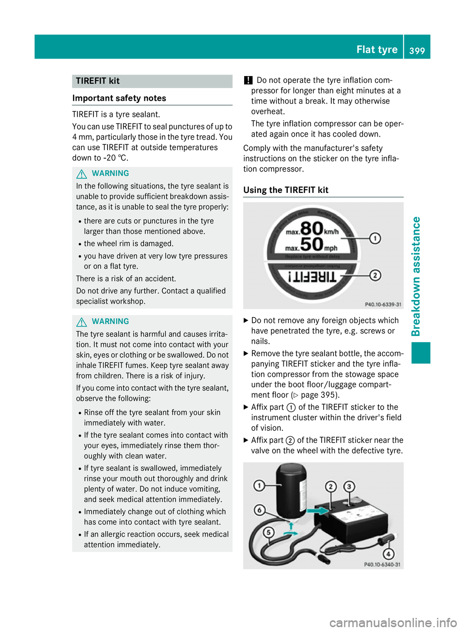
X Affi xpart :of the TIREFIT sticker to the
instrument cluster withi nthe driver's field
of vision.
X Affi xpart ;of the TIREFIT sticker nea rthe
valve on the whee lwitht he defective tyre. Flat tyre
399Breakdow nassistance Z
Page 425 of 497
Important safety notes
The tyr
epressur ewarning system does not
warn you of an incorrectl yset tyr epressure.
Observ ethe note sont herecommended tyre
pressur e(Ypage 420).
The tyr epressur eloss warning does not
replace th eneedtor egularly chec kthe tyre
pressures. An eve nloss of pressur eonsev-
eral tyres at th esame time canno tbedetec-
te dbyt hetyrep ressur eloss warning system.
The tyr epressur emonitor is no table to warn
you of asudde nloss of pressure, e.g. if the
tyr eisp enetrated by aforeign object. In the
event of asudde nloss of pressure, brin gthe
vehicl etoah alt by braking carefully. Avoid
abrup tsteering manoeuvres.
The function of th etyrep ressur eloss warning
system is limited or delayed if:
R snow chains are fitte dtoyour vehicle's
tyres.
R road condition sare wintry.
R you are driving on san dorgravel.
R you adopt averys port ydriving style (cor-
nerin gath igh speeds or driving wit hhigh
rates of acceleration).
R you are towin gaveryh eav yorl argetrailer.
R you are driving wit haheavyload (in the
vehicl eoront heroof).
Restarting th etyrep ressure loss warn-
ing system Restart th
etyrep ressur eloss warning system
if you have:
R changed th etyrep ressure
R changed th ewheels or tyres
R fitte dnew wheels or tyres
X Befor erestarting ,makes ure that th etyre
pressures are set properly on all four tyres
for th erespective operating conditions.
The recommended tyr epressures can be
foun dint hetyrep ressur etable on th efuel
filler flap.
The tyr epressur eloss warning system can
only giv ereliable warning sifyou have set th
ec orrect tyrep ressure. If an incorrect
tyr ep ressur eisset,the se incorrec tvalues
will be monitored.
X Observ ethe note sint hesection on tyre
pressures (Y page 420).
X Mak esure that th ekeyis in position 2in the
ignition loc k(Ypage 179).
X Press the =or; buttononthesteer-
ing whee ltos elect the Serv.
Serv. menu.
X Press the 9or: buttononthesteer-
ing whee ltos elect the Tyrep ressure
Tyr ep ressure
menu.
X Press the abutton.
The Run Fla tIndicator active
Run Fla tIndicator active
Restart Restart with
withOK
OKmessage appear sinthe
multifunction display.
If you wish to confirm th erestart:
X Press the abutton.
The Tyrep ress. now OK?
Tyr ep ress. now OK? message
appear sinthemultifunction display.
X Press the 9or: buttontos elect
Yes
Yes .
X Press the abutton.
The Run Fla tIndicator restarted
Run Fla tIndicator restarted
message appear sinthemultifunction dis-
play.
Afte rateach-in period, th etyrep ressure
loss warning system will monitor th eset
tyr ep ressures of all four tyres.
If you wish to cance lthe restart:
X Press the %button.
or
X When the Tyre
Tyre press. press. now
now OK?
OK?message
appears, press the 9or: buttonto
select Cancel
Cancel .
X Press the abutton.
The tyr epressur evalue sstoredatt helast
restar twill continue to be monitored. 422
Tyre pressureWheels and ty
res
Page 427 of 497
phones, two-way radios) that may be being
operated in or near the vehicle.
Checking the tyr epressure electroni-
cally X
Make sure that the key is in position 2
(Y page 179) in the ignition lock.
X Press the =or; button on the steer-
ing wheel to select the Service
Servicemenu.
X Press the 9or: button to select
Tyre pressure
Tyre pressure.
X Press the abutton.
The curren ttyre pressure for each wheel
will be displayed in the multifunction dis-
play.
If the vehicle has been parked for over
20 minutes, the Tyre Tyrepressures
pressures will
willbe
be
displayed after afew minute sof
displayed after afew minute sof
driving
driving message appears.
After ateach-in period, the tyre pressure
monitor automatically detects new wheels or new sensors. As long as aclear allocation of
the tyre pressure values to the individual
wheels is not possible, the Tyre pressure Tyre pressure
monito ractive
monito ractive display message is shown
instead of the tyre pressure display. The tyre
pressures are already being monitored.
If an emergency spare wheel is fitted, for a
few minutes the system may continue to
show the tyre pressure of the wheel that has
been removed. If this occurs, not ethat the
value displayed for the position where the
spare wheel is fitted is not the same as the
curren ttyre pressure of the emergency spare
wheel.
Warning messages of the tyr epressure
monitor If the tyre pressure monitor detects
apres-
sure loss in one or more tyres, awarning mes-
sage is shown in the multifunction display and
the yellow tyre pressure monitor warning
lamp comes on.
R If the Please correc ttyre pressure
Please correc ttyre pressure
message appears in the multifunction dis- play, the tyre pressure in at least one tyre is
too low and must be corrected at the next
opportunity.
R If the Check tyre(s) Check tyre(s) message appears in
the multifunction display, the tyre pressure in one or more tyres has dropped signifi-
cantly and the tyres must be checked.
R If the Warnin gtyre defect
Warnin gtyre defect message
appears in the multifunction display, the
tyre pressure in one or more tyres has drop-
ped suddenly and the tyres must be
checked.
Observ ethe instructions and safety notes in
the display messages in the "Tyres" section
(Y page 322).
If the wheel position sonthe vehicle are inter-
changed, the tyre pressures may be displayed for the wrong position sfor as hort time. After
af ew minutes of driving, this is rectified and
the tyre pressures are displayed for the cor-
rect positions.
Restarting the tyr epressure monitor When you restart the tyre pressure monitor,
all existing warning messages are deleted and
the warning lamps go out. The monitor uses
the currently set tyre pressures as the refer-
enc evalues for monitoring. In most cases, the
tyre pressure monitor will automatically
detec tthe new referenc evalues after you
have changed the tyre pressure. However,
you can also define referenc evalues man-
ually as described here. The tyre pressure
monitor then monitors the new tyre pressure values.
X Use the table on the inside of the fuel filler
flap to ensure that the tyre pressure is set
correctly in all four tyres for the current
operatin gconditions.
Also observe the notes in the section on
tyre pressures (Y page 420).
X Make sure that the key is in position 2in the
ignition lock.
X Press the =or; button on the steer-
ing wheel to select the Service Servicemenu. 424
Tyrep
ressureWheels and tyres
Page 431 of 497
jack could tip ove
rwitht he vehicl eraised.
There is ariskofi njury.
Onl yposit iont he jack at the appropriate jack-
ing point of the vehicle. The base of the jack
must be positioned vertically, directl yunder
the jacking point of the vehicle.
Observe the following when raising the vehi-
cle:
R to rais ethe vehicle, onl yusethe vehicle-
specific jack tha thas been teste dand
approved by Mercedes-Benz. If the jack is
used incorrectly ,itcould tip ove rwhile the
vehicl eisraised.
R the jack is designe donlytor aiseand hold
the vehicl efor as hort time whil eawheel
is being changed. It is not suitabl efor per-
formin gmaintenance work under the vehi-
cle.
R avoi dchanging the whee lonuphilland
downhil lslope s.
R befor eraisi ng the vehicle, safeguard it from
rolling away by applying the parking brake
and positioning whee lchocks. Never
release the parking brake whil ethe vehicle
is raised.
R the jack must be place donafirm, flatand
non-sli psurface. On aloo se surface, a
large ,flatl oad- bearing underlay must be
used .Ona slippery surface, anon-slip
underlay must be used ,e.g.r ubbe rmats.
R do not us ewoode nblocks or similar
objects as ajack underlay .Otherwise, the
jack will not be able to achieve its load-
bearing capacity du etothe restricted
height.
R make sure tha tthe distance between the
undersid eofthe tyres and the ground does
not exceed 3cm.
R neve rplace your hands or fee tunder the
raised vehicle.
R do not li eunder the vehicle.
R do not start the engine when the vehicl eis
raised. R
do not open or close adoorort he boot lid/
tailgate when the vehicl eisraised.
R make sure tha tnopersons ar epresent in
the vehicl ewhent he vehicl eisraised.
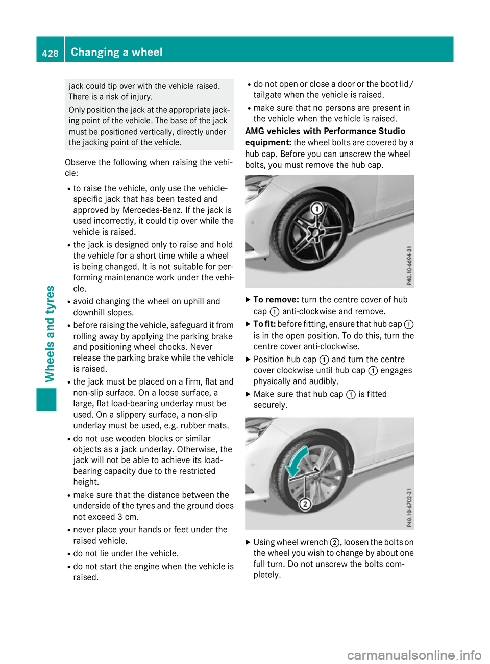
AM Gvehicle swithP erformanc eStudio
equipment: the wheelbolts ar ecovered by a
hu bc ap.B efore yo ucan unscrew the wheel
bolts ,you must remove the hu bcap. X
To remove: turnthe centre cove rofhub
cap :anti-clockwise and remove.
X To fit: beforefitting, ensur etha thub cap :
is in the open position. To do this, tur nthe
centre cove ranti-clockwise.
X Positio nhub cap :and tur nthe centre
cove rclockwise unti lhub cap :engages
physicall yand audibly.
X Make sure tha thub cap :is fitted
securely. X
Using whee lwrench ;,l oosent he bolts on
the whee lyou wish to change by abou tone
full turn. Do not unscrew the bolts com-
pletely. 428
Changin
gawheelWheels an dtyres
Page 485 of 497
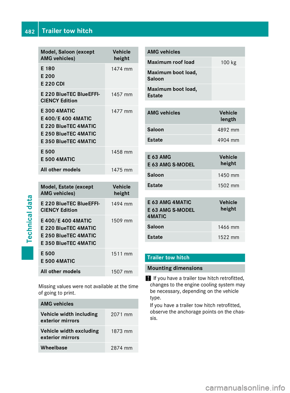
Model
,Saloon (except
AMG vehicles) Vehicle
height E1
80
E2 00
E2 20 CDI 1474 mm
E2
20 BlueTEC BlueEFFI-
CIENCY Edition 1457 mm
E3
00 4MATIC
E4 00
E400 4MATIC
E2 50 BlueTEC 4MATIC
E3 50 BlueTEC 4MATIC 1477 mm
E5
00
E5 00 4MATIC 1458 mm
All other models
1475 mm
Model
,Estate (except
AMG vehicles) Vehicle
height E2
20 BlueTEC BlueEFFI-
CIENCY Edition 1494 mm
E2
50 BlueTEC 4MATIC
E3 50 BlueTEC 4MATIC 1509 mm
E5
00
E5 00 4MATIC 1511 mm
All other models
1507 mm
Missing values were not available at the time
of going to print. AMG vehicles
Vehicle width including
exterio rmirrors 2071 mm
Vehicle width excluding
exterio rmirrors 1873 mm
Wheelbase
2874 mm AMG vehicles
Maximum roof load
100 kg
Maximum bootl
oad,
Saloon Maximum bootl
oad,
Estate AMG vehicles Vehicle
length Saloon
4892 mm
Estate
4904 mm
E63A
MG
E63A MG S-MODEL Vehicle
height Saloon
1450 mm
Estate
1502 mm
E63A
MG 4MATIC
E63A MG S-MODEL
4MATIC Vehicle
height Saloon
1466 mm
Estate
1522 mm
Trailer tow hitch
Mountin
gdimensions
! If you have
atrailer tow hitch retrofitted,
changes to the engine cooling system may
be necessary, depending on the vehicle
type.
If you have atrailer tow hitch retrofitted,
observe the anchorage points on the chas- sis. 482
Trailer tow hitchTechnical data E2
20 BlueTEC 4MATIC/
E4 00
E400 4MATIC
/
E2 20 BlueTEC 4MATIC