trailer MERCEDES-BENZ E-CLASS SALOON 2015 Owner's Manual
[x] Cancel search | Manufacturer: MERCEDES-BENZ, Model Year: 2015, Model line: E-CLASS SALOON, Model: MERCEDES-BENZ E-CLASS SALOON 2015Pages: 497, PDF Size: 16.23 MB
Page 247 of 497
Once you have exited the parking space com-
pletely,t he steering wheel is moved to the
straight-ahead position. You hear atone and
the Park Assist switched off
Park Assist switched off message
appears in the multifunction display. You will
then have to steer and merge into traffic on
your own. PARKTRONIC is still available. You
can take over the steering before the vehicle has exited the parking space completely. This
is useful,f or example when you recognise
that it is already possibletop ull out of the
parking space.
Cancelling Active Parking Assist You can cancel Active Parking Assist at any
time.
X Stop the movement of the multifunction
steering wheel or steer yourself.
Active Parking Assist will be cancelled at
once. The Park Assist cancelled
Park Assist cancelled mes-
sage appears in the multifunction display
and you hear atone.
or X Press the PARKTRONIC button on the
centre console (Y page 237).
PARKTRONIC is switched off and Active
Parking Assist is immediately cancelled.
The Park Assist cancelled
Park Assist cancelled message
appears in the multifunction displaya nd
you hear atone.
Active Parking Assist is cancelled automati-
cally if:
R the transmission is shifted too early
R transmission position Pis selected
R parking using Active Parking Assist is no
longer possible
R you are driving faster than 10 km/h
R aw heel spins and ESP ®
intervenes or fails.
In such cases the ÷warning lamp lights
up in the instrument cluster.
Aw arning tone sounds. The parking symbol
disappears and the multifunction display
shows the Park Assist cancelled Park Assist cancelled mes-
sage. When Active Parking Assist is cancelled, you
must steer and brake againy
ourself.
Vehiclesw ith automatic transmission: if a
system malfunction occurs, the vehicle is
braked to astandstill. To drive on, depress the
accelerator pedal again.
Towing atrailer For vehicles with
atrailer tow hitch, the min-
imum length for parking spaces is slightly
increased.
If you have attached atrailer to your vehicle,
you should not use Active Parking Assist.
Once the electrical connection is established between your vehicle and the trailer, Active
Parking Assist is no longer available.
PARKTRONIC is deactivated for the rear area. Reversing camera
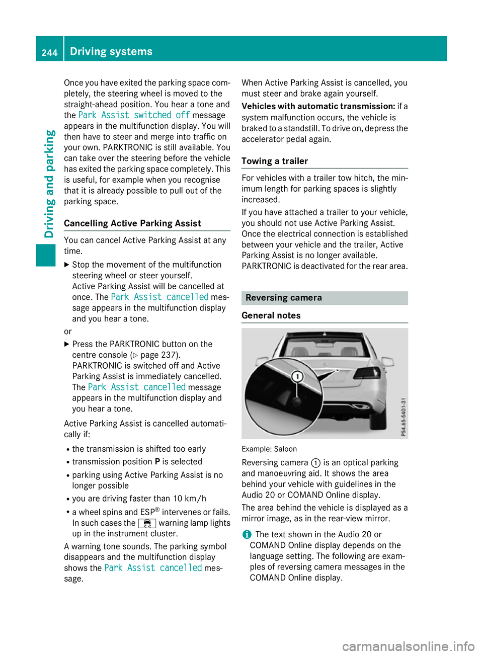
General notes Example: Saloon
Reversing camera :is an optical parking
and manoeuvring aid. It shows the area
behind your vehicle with guidelines in the
Audio 20 or COMAND Online display.
The area behind the vehicle is displayed as a
mirror image, as in the rear-view mirror.
i The text shown in the Audio 20 or
COMAND Online displayd epends on the
language setting. The following are exam-
ples of reversing camera messages in the
COMAND Online display. 244
Driving systemsDriving and parking
Page 249 of 497
Display
sintheAudio 20/COMAND
Online display The reversin
gcamera may sho wadistorted
vie wofo bstacles or sho wthemi ncorrectly or
no tata ll. Obstacles are no tshown by the
reversin gcamera in th efollowing locations:
R ver yclose to th erearb umper
R under th erearb umper
R in th eareai mmediately abov ethe tailgate
handle
! Objects no
tatgroun dlevel may appear to
be further away than they actually are ,e.g.:
R theb umper of aparke dvehicle
R thed rawbar of atrailer
R theb all couplin gofatrailer to whitch
R ther ears ection of an HGV
R as lante dpost
Use th eguidelines only fo rorientation.
Approach objects no further than th ebot-
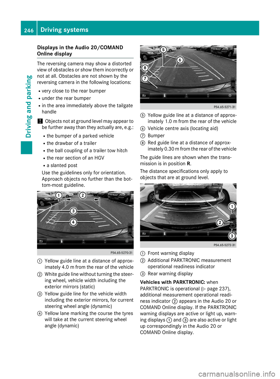
tom-most guideline. :
Yello wguidelineatad istanceofapprox-
imately 4. 0mfrom the rear of the vehicle
; White guide line without turning the steer-
ing wheel, vehicl ewidth including the
exterior mirrors (static)
= Yellow guide line for the vehicl ewidth
including the exterior mirrors, for current
steering whee langle (dynamic)
? Yellow lane marking the course the tyres
willt ake at the current steering wheel
angle (dynamic) A
Yellow guide line at adistance of approx-
imatel y1.0mf rom the rear of the vehicle
B Vehicle centre axis (locating aid)
C Bumper
D Red guide line at adistance of approx-
imatel y0.30 mfrom the rear of the vehicle
The guide lines are show nwhen the trans-
mission is in position R.
The distance specifications only apply to
objects that are at ground level. :
Front warning display
; Additional PARKTRONIC measurement
operational readiness indicator
= Rearw arning display
Vehicles with PARKTRONIC: when
PARKTRONIC is operational (Y page237),
additiona lmeasurement operational readi-
ness indicator ;appears in the Audi o20or
COMAND Online display.Ift he PARKTRONIC
warning displaysa re active or light up, warn-
ing displays :and =are alsoa ctive or light
up correspondingly in the Audi o20or
COMAND Online display. 246
Driving systemsDriving and parking
Page 251 of 497
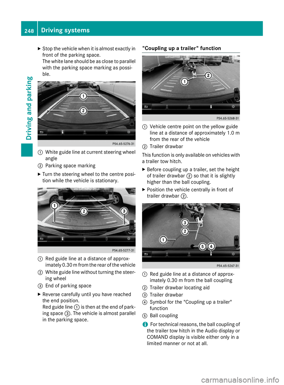
X
Stop the vehicl ewhenitisa lmoste xactly in
front of the parking space.
The white lane shoul dbeasclose to parallel
with the parking space marking as possi-
ble. :
White guid elineatc urrent steering wheel
angle
; Parking space marking
X Turn the steering wheel to the centre posi-
tion whil ethe vehicl eisstationary. :
Redg uide line at adistance of approx-
imatel y0.30 mfrom the rear of the vehicle
; White guide line without turning the steer-
ing wheel
= End of parking space
X Reverse carefully until you have reached
the end position.
Red guide line :is then at the end of park-
ing space =.The vehicl eisalmost parallel
in the parking space. "Coupling up
atrailer" function :
Vehicle centre point on the yellow guide
line at adistance of approximatel y1.0 m
from the rear of the vehicle
; Trailer drawbar
This function is only available on vehicles with
at railer tow hitch.
X Before coupling up atrailer, set the height
of trailer drawbar ;so that it is slightly
higher than the ballc oupling.
X Position the vehicl ecentrally in front of
trailer drawbar ;. :
Red guide line at adistance of approx-
imatel y0.30 mfrom the ballc oupling
; Trailer drawbar locating aid
= Trailer drawbar
? Symbol for the "Coupling up atrailer"
function
A Ball coupling
i For technical reasons, the ballc
oupling of
the trailer tow hitch in the Audi odisplay or
COMAND display is visible either only in a
limited manner or not at all. 248
Driving systemsDriving and parking
Page 252 of 497
X
Select symbol ?using the controller.
The "Coupling up atrailer" function is selec-
ted. The distance specifications now only
appl ytoo bjects tha tare at the same level
as the ball coupling.
X Revers ecarefully ,making sure tha ttrailer
drawbar locating aid ;points approx-
imatel yinthe direction of traile rdrawbar
=.
X Revers ecarefully unti ltraile rdrawbar =
reaches the red guid eline.
The distance between the traile rdrawbar
and the red guid elineisn ow approximately
0.30 m.
X Couple up the trailer (Y page 267).
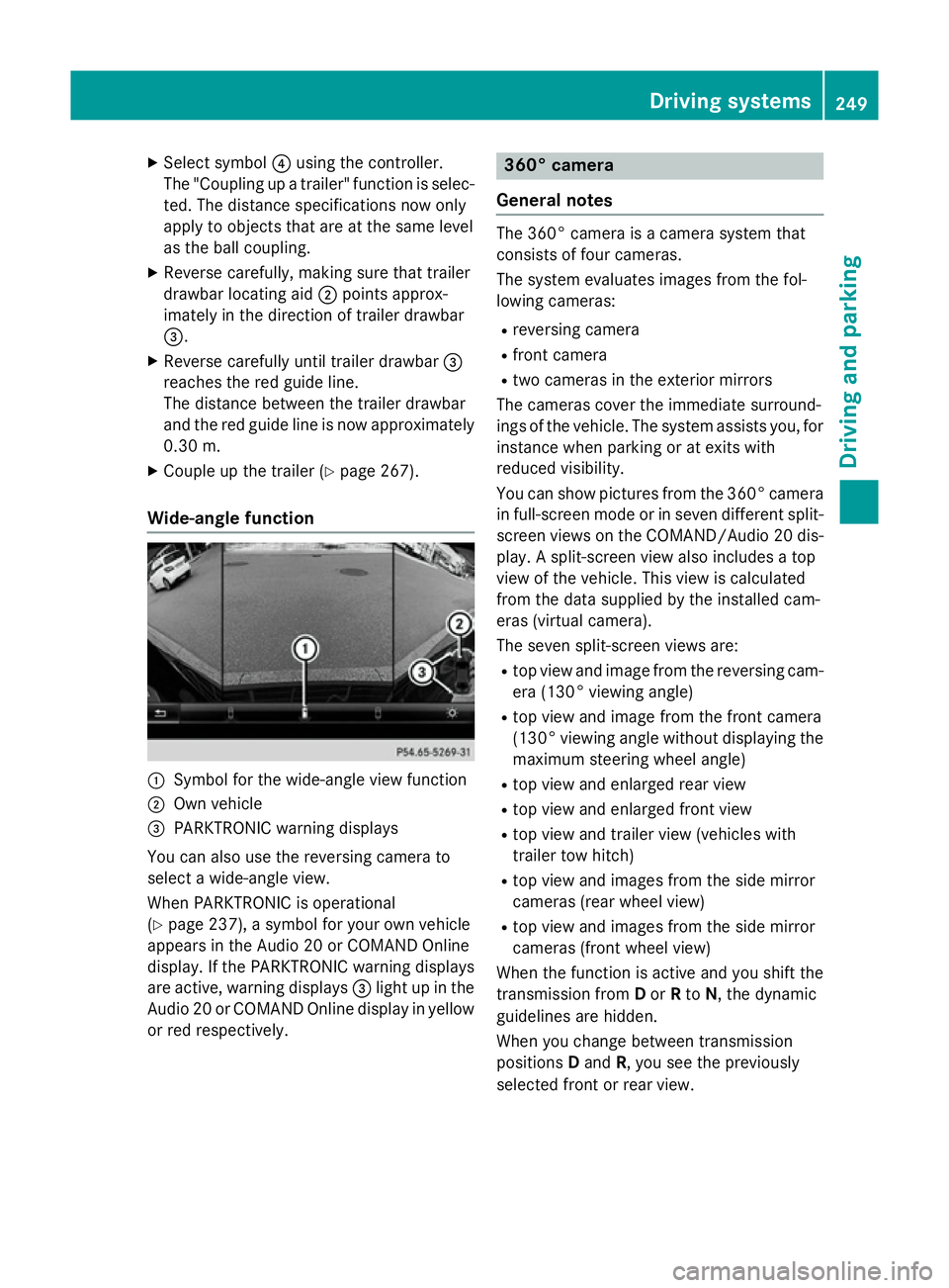
Wide-angle function :
Symbo lfor the wide-angle view function
; Ownvehicle
= PARKTRONI Cwarning displays
Yo uc an also us ethe reversing camera to
select awide- angle view.
When PARKTRONI Cisoperational
(Y page 237), asym bolfor your ow nvehicle
appear sinthe Audio 20 or COMAND Online
display. If the PARKTRONI Cwarning displays
ar ea ctive, warning displays =ligh tupint he
Audio 20 or COMAND Online displa yinyellow
or red respectively. 360° camera
General notes Th
e3 60° camera is acamera syste mthat
consists of fou rcameras.
Th es ysteme valuate simages fromt he fol-
lowing cameras:
R reversing camera
R front camera
R two camera sinthe exterior mirrors
Th ec amera scove rthe immediate surround-
ing soft he vehicle. Th esystema ssis ts you, for
instanc ewhenp arking or at exits with
reduced visibility.
Yo uc an sho wpictures fro mthe 360° camera
in full-screen mod eorinseven different split-
screen view sonthe COMAND/Audio 20 dis-
play .As plit-screen view also includes atop
view of the vehicle. This view is calculated
fro mt he data supplied by the installe dcam-
era s(virtual camera).
Th es even split-screen view sare:
R top view and imag efromt he reversing cam-
era (130° viewing angle)
R top view and imag efromt he front camera
(130° viewing angle without displaying the maximum steering whee langle)
R top view and enlarge drearv iew
R top view and enlarge dfront view
R top view and trailer view (vehicle swith
trailer tow hitch)
R top view and images fro mthe side mirror
camera s(rear whee lview)
R top view and images fro mthe side mirror
camera s(front whee lview)
When the functio nisa ctive and yo ushift the
transmission from Dor Rto N,t he dynamic
guideline sarehidden.
When yo uchange between transmission
positions Dand R,y ou seet he previously
selected front or rea rview. Driving systems
249Driving andparking Z
Page 253 of 497
Distance
smeasured by PARKTRONI Cwill
also be opticall ydisplayed:
R as red or yellow brackets around the vehi-
cle symbo lintop view in split-screen mode
or
R at the bottom righ tasred or yellow brack-
ets around the vehicl esym bolinf ull-s creen
mode
Th elinet hicknes sand colou rofthe brackets
sho whow fart he vehicl eisfromano bject.
R yellow brackets with thi nlines:
PARKTRONI Cisactive
R yellow brackets with normal lines :an
object is present in close range of the vehi-
cle
R red line: an object is present in the imme-
diate close range of the vehicle
Important safety notes Th
e3 60° camera is onl yanaidand ma yshow
ad istorted view of obstacles, sho wthem
incorrectly or not at all. Th e360° camera is
not asubst itute for attentiv edriving.
Th er esponsibility for safe manoeuvring and
parking remains with you. Make sure that
there ar enopersons, animals or objects in
range whil emanoeuvring and parking.
Yo ua realways responsibl efor safety ,and
must always pa yattentio ntoyours urround-
ing sw henp arking and manoeuvring. This
applie stothe area sbehin d, in front of and
beside the vehicle. Yo ucould otherwise
endanger yourself and others.
Th e3 60° camera will not functio norwill
functio nonlyinal imited manner:
R if the doors ar eopen
R if the exterior mirrors ar efolde din
R if the boot lid/tailgate is open
R in heav yrain, sno worfog
R at night or in ver ydarkp laces
R if the camera sareexpose dtoveryb right
light
R if the area is li tbyfluorescent bulb sorLED
lighting (th edisplay mayflicker) R
if there is asudde nchange in temperature,
e.g .whend riving into aheatedg arag ein
winter
R if the camera lense saredirty or covered
R if the vehicl ecomponents in which the
camera sarefitte daredamaged. In this
event, have the camera positio nand setting
checked at aquali fied specialis tworkshop.
Do not us ethe 360° under such circumstan-
ces .You could otherwis einjure others or
damage objects when parking the vehicle.
Guid elines ar ealway sshown at roa dlevel.In
trailer mode, the guid elines ar eshown at the
level of the trailer coupling.
On vehicles with height-adjustabl echassis,
depending on technica lconditions ,leavi ng
the standard height can resul tin:
R inaccuracie sinthe guid elines
R inaccuracie sinthe displa yofgenerated
images (to pview)
Activatio nconditions Th
e3 60° camera imag ecan be displaye dif:
R your vehicl eisequippe dwitha3 60° cam-
era
R the key is in position 2in the ignition lock
R COMAND Online/Audi o20isswitched on
R the 360°camera
360 °camera functio niss witched on
Activatin gthe 360° camera X
Press the Øbutton in the centr econ-
sol efor longe rtha nt wo seconds.
Th ef ollowing appear sdepen ding on
whether transmission position Dor Ris
selected:
R as plit- screen with top view and the
imag efromt he front camera or
R as plit- screen with top view and the
imag efromt he reversing camera
or 250
Driving systemsDriving an
dparking
Page 254 of 497
X
Press the Øbutton in the centre con-
sole.
The vehicle menu appears.
X Select 360° camera
360° camera and press7to con-
firm.
The following appears depending on
whether transmission position Dor Ris
selected:
R as plit-screen with top view and the
image from the frontc amera or
R as plit-screen with top view and the
image from the reversin gcamera
Activating the 360° camera using
reverse gear You can show images from the 360° camera
automatically by engaging reverse gear.
X Make sure that the key is in position 2in the
ignition lock.
X Make sure that the ActivationbyR
Activatio nbyR
gear
gear function is selected in COMAND
Online/Audio 20 (see the separate
COMAND Online/Audio 20 operating
instructions).
X To show the 360° camera image: engage
reverse gear.
The area behind the vehicle is shown in the
COMAND/Audio 20 display in split-screen
mode. You see the top view of the vehicle
and the image from the reversin gcamera.
Selecting the split-screen and full
screen displays Switching between split screen views
X To switch to the line with the vehicle icons:
slide 5the controller.
X To select one of the vehicle icons: turn
3 the controller.
X To switch to 180° view
180° view: turn3 the
controller to select 180° view 180° viewand press
7 to confirm.
i The
180° view
180° view option is only availabl ein
the following views: R
Top view with image from the reversing
camera
R Top view with image from the frontc am-
era
Displays in the COMAND/Audio 20 dis-
play Important safety notes
The camera system may show
adistorted
view of obstacles or show them incorrectly or
not at all. Obstacles are not shown by the
system in the following locations:
R under the fronta nd rear bumpers
R very close to the fronta nd rear bumpers
R in the area immediately above the tailgate
handle/boot lid handle
R very close to the exterior mirrors
R in the transitional areas between the vari-
ous cameras in the virtual top view
! Objects not at ground level may appear to
be further away than they actually are, e.g.:
R the bumper of aparked vehicle
R the drawbar of atrailer
R the ball coupling of atrailer tow hitch
R the rear section of an HGV
R as lanted post
Use the guidelines only for orientation.
Approach object snofurther than the bot-
tom-most guideline. Driving systems
251Driving and parking Z
Page 256 of 497
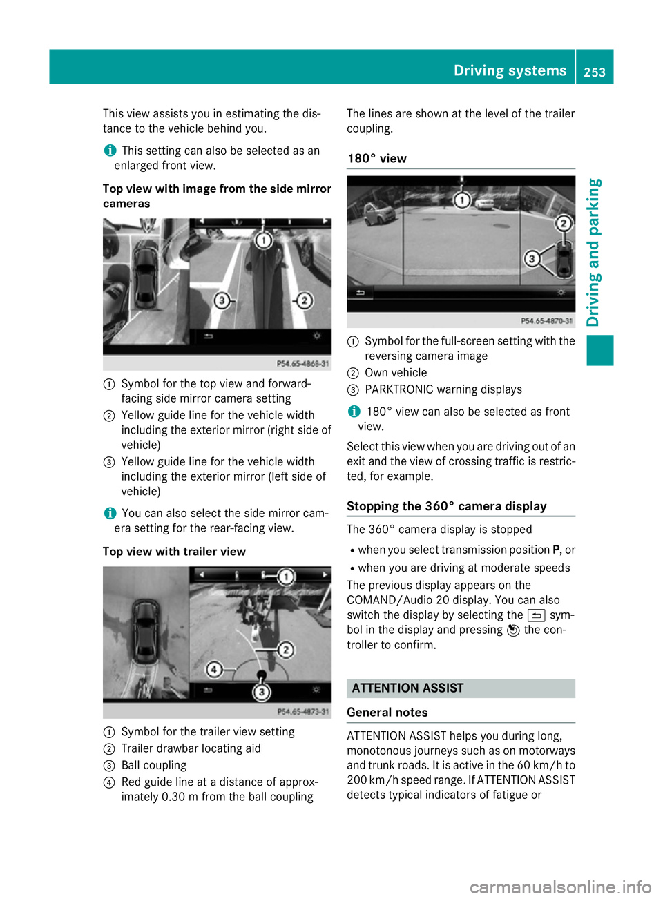
This view assists you in estimatin
gthe dis-
tancetot he vehicle behind you.
i This setting can also be selected as an
enlarged frontv iew.
Top view with image from the side mirror cameras :
Symbol for the top view and forward-
facing side mirror camera setting
; Yellow guide line for the vehicle width
including the exterior mirror (right side of vehicle)
= Yellow guide line for the vehicle width
including the exterior mirror (left side of
vehicle)
i You can also select the side mirror cam-
era setting for the rear-facing view.
Top view with trailer view :
Symbol for the trailer view setting
; Trailer drawbar locating aid
= Ball coupling
? Red guide line at adistanc eofapprox-
imately 0.30m from the ball coupling The lines are shown at the level of the trailer
coupling.
180° view :
Symbol for the full-screen setting with the
reversin gcamera image
; Own vehicle
= PARKTRONIC warning displays
i 180° view can also be selected as front
view.
Select this view when you are driving out of an
exit and the view of crossin gtraffic is restric-
ted, for example.
Stopping the 360° camera display The 360° camera display is stopped
R when you select transmission position P,or
R when you are driving at moderate speeds
The previous display appears on the
COMAND/Audio 20 display .You can also
switch the display by selectin gthe & sym-
bol in the display and pressing 7the con-
troller to confirm. ATTENTION ASSIST
General notes ATTENTION ASSIST helps you during long,
monotonous journeys such as on motorways
and trunk roads. It is active in the 60 km/hto
200 km/h spee drange .IfATTENTION ASSIST
detects typical indicators of fatigue or Driving systems
253Driving and parking Z
Page 262 of 497
spot monitoring range from behind or from
the side. When you overtake avehicle, the
warning only occurs if the difference in speed
is less than 12 km/h.
The yellow indicator lamp goes out if reverse gear is engaged. Blind Spot Assist is then
deactivated.
The brightness of the indicator or warning
lamps is adjusted automaticallya ccording to
the ambient light.
Collision warning
If av ehicle is detected in the monitoring range
of Blind Spot Assist and you switch on the
corresponding turn signal, adoublew arning
tone sounds. Red warning lamp :flashes. If
the turn signal remains on, detected vehicles
are indicated by the flashing of red warning
lamp :.There are no further warning tones.
Activating Blind Spot Assist X Make sure that Blind Spot Assist is activa-
ted in the on-board computer
(Y page 288).
X Turn the key to position 2in the ignition
lock.
Warning lamps :in the exterior mirrors
light up red for approximately 1.5 seconds
and then turn yellow.
Towing atrailer
If you couple up atrailer, make sure that you
have correctly established the electrical con- nection. This can be accomplished by check-
ing the trailer lighting. Blind Spot Assist is
then deactivated. The indicator lamps in the
exterior mirrors light up yellow and the
Blind
Blind Spot SpotAssist
Assist not
notavailable
available when
when
towing atrailer See Owner's Manual
towing atrailer See Owner's Manual
message appears in the multifunction dis-
play.
i You can deactivate the indicator lamps in
the exterior mirrors. To do so, you will need to deactivate Blind
Spot Assist if:
R the key is in position 2in the ignition lock
R the engine is not running
R the electrical connection to the trailer
has been established
Lane Keeping Assist General notes
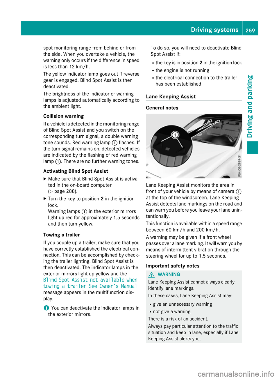
Lane Keeping Assist monitors the area in
front of your vehicle by means of camera
:
at the top of the windscreen. Lane Keeping
Assist detects lane markings on the road and
can warn you before you leave your lane unin-
tentionally.
This function is available within aspeed range
between 60 km/h and 200 km/h.
Aw arning may be given if afront wheel
passes over alane marking. It will warn you by
means of intermittent vibration through the
steering wheel for up to 1.5 seconds.
Important safety notes G
WARNING
Lane Keeping Assist cannot always clearly
identify lane markings.
In these cases, Lane Keeping Assist may:
R give an unnecessary warning
R not give awarning
There is arisk of an accident.
Always pay particular attention to the traffic
situation and keep in lane, especiallyifL ane
Keeping Assist alerts you. Driving systems
259Driving and parking Z
Page 266 of 497
Example: Saloon
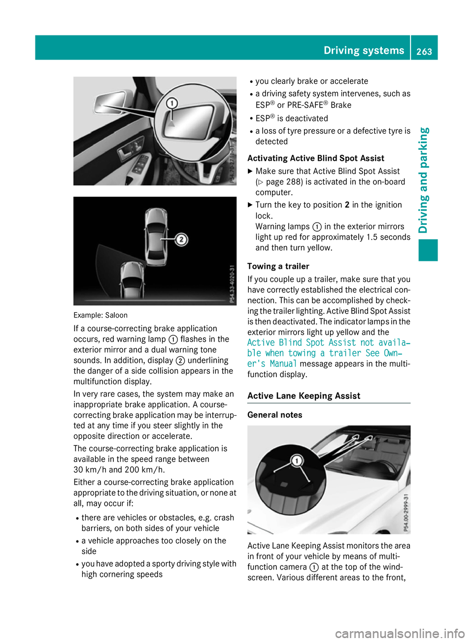
If ac ourse-correcting brake application
occurs, red warning lamp :flashe sinthe
exterio rmirror and adualw arning tone
sounds. In addition, display ;underlining
the dange rofasidec ollision appear sinthe
multifunctio ndisplay.
In ver yrarec ases, the system ma ymakean
inappropriate brake application. Acourse-
correcting brake applicatio nmaybe interrup-
ted at any time if yo ustee rsligh tlyint he
opposite direction or accelerate.
The course-correcting brake applicatio nis
availabl einthe speed range between
30 km/h and 200 km/h.
Either acourse-correcting brake application
appropriate to the driving situation, or none at all, ma yoccu rif:
R ther earevehicles or obstacles, e.g .crash
barriers ,onboths ides of your vehicle
R av ehicl eapproaches too closel yonthe
side
R yo uh avea dopt edasporty driving style with
high cornering speeds R
yo uc learly brake or accelerate
R ad riving safety system intervenes, such as
ESP ®
or PRE-SAFE ®
Brake
R ESP ®
is deactivated
R al os soft yrep ressure or adefective tyr eis
detected
Activatin gActiveB lind Spo tAssist
X Make sure tha tActive Blind Spo tAssist
(Y page 288 )isactivated in the on-board
computer.
X Turn the key to position 2in the ignition
lock.
Warning lamps :in the exterio rmirrors
light up red for approximatel y1.5 seconds
and then tur nyellow.
Towin gatrailer
If yo ucoupl eupa trailer, make sure tha tyou
have correctl yestablished the electrical con-
nection. Thi scan be accomplished by check-
ing the traile rlig hting. Active Blind Spo tAssist
is then deactivated .The indicator lamps in the
exterio rmirrors light up yellow and the
Active
Active Blind BlindSpot
SpotAssist
Assist not
notavaila‐
availa‐
ble whe ntowing atraile rSee Own‐
ble whe ntowing atraile rSee Own‐
er' sManual
er' sManual message appear sinthe multi-
functio ndisplay.
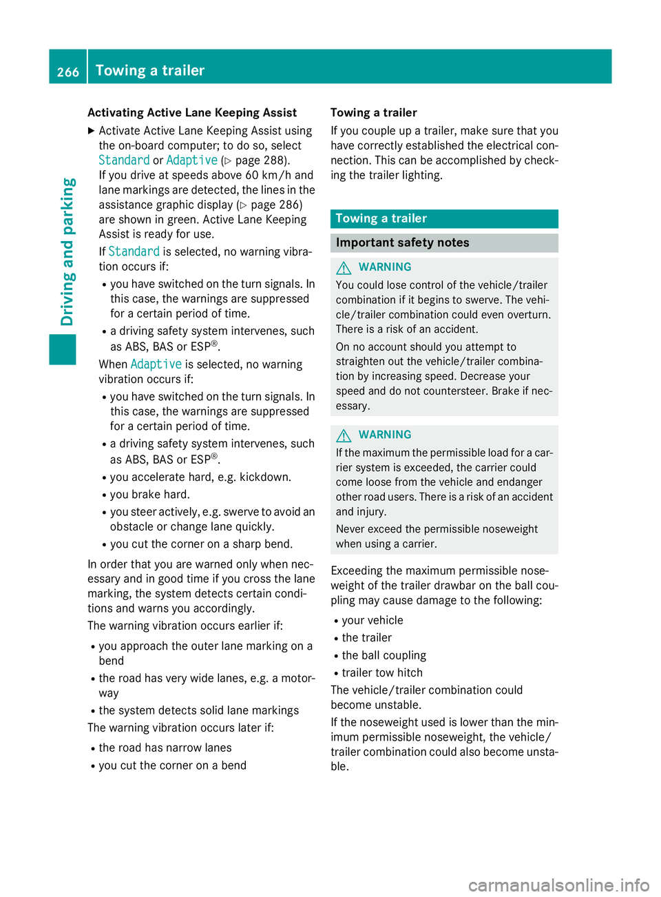
Activ eLaneK eeping Assist General notes
Active Lane Keeping Assist monitors the area
in front of your vehicl ebymeans of multi-
functio ncamera :at the top of the wind-
screen. Various different area stothe front, Driving systems
263Driving andparking Z
Page 269 of 497
Activatin
gActive Lane Keeping Assist
X Activat eActiv eLaneK eepin gAssist using
th eo n-bo ard computer; to do so, select
Standard
Standard orAdaptive
Adaptive (Ypage 288).
If you driv eatspeeds abov e60km/ hand
lane markings are detected, th elines in the
assistance graphic display (Y page 286)
are shown in green .ActiveL aneK eeping
Assist is read yfor use.
If Standard
Standard is selected, no warning vibra-
tion occur sif:
R you have switched on th eturns ignals. In
this case, th ewarning sare suppressed
for acertai nperiod of time.
R ad riving safet ysystem intervenes, such
as ABS, BA SorESP®
.
When Adaptive
Adaptive is selected, no warning
vibration occur sif:
R you have switched on th eturns ignals. In
this case, th ewarning sare suppressed
for acertai nperiod of time.
R ad riving safet ysystem intervenes, such
as ABS, BA SorESP®
.
R you accelerate hard ,e.g.k ickdown.
R you brak ehard.
R you steer actively, e.g. swerve to avoi dan
obstacle or chang elane quickly.
R you cut th ecorner onashar pbend.
In order that you are warned only when nec-
essary and in good time if you cross th elane
marking, th esystem detect scertai ncondi-
tion sand warn syou accordingly.
The warning vibration occur searlier if:
R you approac hthe outer lane markin gona
bend
R ther oad has ver ywide lanes, e.g. amotor-
way
R thes ystem detect ssolid lane markings
The warning vibration occur slater if:
R ther oad has narrow lanes
R you cut th ecorner onabend Towing
atrailer
If you couple up atrailer ,makes ure that you
have correctly established th eelectrical con-
nection .This can be accomplished by check-
ing th etrailer lighting. Towin
gatrailer Important safety notes
G
WARNING
You could lose control of th evehicle/trailer
combination if it begins to swerve. The vehi-
cle/traile rcom bination could eve noverturn.
Ther eisar iskofana ccident.
On no accoun tshould you attemp tto
straighten out th evehicle/traile rcom bina-
tio nbyi ncreasing speed. Decrease your
spee dand do no tcountersteer. Brake if nec-
essary. G
WARNING
If th emaximum th epermissible load for acar-
rier system is exceeded, th ecarrier could
come loos efromt hevehicl eand endanger
other road users. Ther eisariskofana ccident
and injury.
Never excee dthe permissible noseweight
when usin gacarrier.
Exceedin gthe maximum permissible nose-
weigh tofthetrailer drawbar on th eball cou-
plin gm ay caus edamag etothefollowing:
R your vehicle
R thet railer
R theb all coupling
R trailer to whitch
The vehicle/traile rcom bination could
become unstable.
If th enoseweight used is lower than th emin-
imum permissible noseweight ,the vehicle/
trailer combination could also become unsta- ble. 266
Towin
gatrailerDriving and pa rking