light MERCEDES-BENZ E-CLASS SALOON 2017 Owners Manual
[x] Cancel search | Manufacturer: MERCEDES-BENZ, Model Year: 2017, Model line: E-CLASS SALOON, Model: MERCEDES-BENZ E-CLASS SALOON 2017Pages: 497, PDF Size: 10.38 MB
Page 5 of 497
At
agl ance .................................................... 6
Cockpit ........................................................... 6
Overview of warning and indicator lamps .... .10
Overhead contro l panel ................................ 14
Door control panel and seat adjustment ....... 16
Emergencies and breakdowns ...................... 18Digital Owner's Manual
.............................20
Calling up the Digital Owner's Manual ..........20 Genera
l notes............................................. 21
Pr otection of the environment ......................21
Ta ke -ba ckof end-of-life vehicles ...................21
Mercedes-Benz GenuineParts ....................... 22
Owner's Manual ...........................................23
Operating saf ety .......................................... .23
Declaration of Conformity ............................. 24
Diagno stics connection ................................ 26
Qualified specialist workshop ....................... 26
Ve hicle registration ....................................... 27
Cor rect use of theve hicle ............................. 27
Implied warranty .......................................... .27
QR code forre scue card ...............................27
Ve hicle data storage .....................................28 Copyright ...................................................... 30 Occupant saf
ety......................................... 31
Re stra int sy stem ...........................................31
Seat belts ..................................................... 33
Airbags ......................................................... 38
PRE-SAFE ®
sy stem ....................................... 45
Children in theve hicle ..................................46
No tes on pets in theve hicle .........................65 Opening and closing
.................................. 67
Ke y ................................................................ 67
Doo rs............................................................ 71
Boot .............................................................. 76
Ro ller sunblinds ............................................ 81
Side windo ws............................................... 83
Sliding sunroof ............................................. 86
Anti-theft pr otection .....................................91 Seats and
stowing ...................................... 94
No tes on the cor rect driver's seat position ... 94
Seats ............................................................ 95
St eering wheel ............................................ 103Using
the memory function ........................ 106
St ow age areas ............................................ 107
Cup holders ................................................ .118
Ashtr ayand cigar ette lighter ...................... .120
Soc kets ....................................................... 121
Wi reless charging of the mobile phone
and connection with theex terior aerial .......1 24
Fitting or removing thefloor mats .............. 12 6 Light and sight
......................................... 127
Exterior lighting .......................................... 127
Interior lighting ........................................... 13 6
Changing bulbs (on lyforve hicles with
halogen headlamp s) .................................... 137
Wi ndsc reen wipers and windscreen
wa sher sy stem ............................................ 14 0
Mir rors ........................................................ 14 2
Operating the sun visors ............................. 14 5
Infrared reflective windscreen .................... 14 6 Climate control
......................................... 147
Overview of climate contro l systems ..........1 47
Operating the climate control sy stem ......... 14 8 2
Contents
Page 6 of 497
Driving and pa
rking ................................. 15 9
Driving ........................................................ 15 9
DY NA MIC SELECT switch ............................1 70
Manual transmission .................................. 17 0
Au tomatic transmission .............................. 172
Re fuelling .................................................... 176
Pa rking ........................................................ 181
Driving and driving sa fety sy stems .............1 90
Tr ailer hit ch................................................. 24 4
Bicycle rack ................................................ 24 8Instrument Display and on-board
compu ter.................................................. 251
Instrument display overview ...................... .251
Overview of the buttons on thesteering
wheel ..........................................................2 52
Operating the on-board computer .............. 253
Setting the additional value range .............. 254
Overview of displ ays on the multifunc‐
tion display .................................................2 55
Ad justing the instrument lighting ............... 255
Menus and submenus ................................ 256
Head-up Display ......................................... 262 Multimedia sy
stem .................................. 264
Overview and operation .............................. 264
Sy stem settings .......................................... 273
Garmin ®
MAP PIL OTnavigation module ...... 276
Te lephone .................................................. .277
Online and Internet functions ..................... 293
Media ......................................................... 295
Ra dio .......................................................... 301
Sound .........................................................3 04 Maintenance and care
.............................306
ASS YST PLUS service inter val display ........ 306
Engine compartment .................................. 307
Cleaning and care ...................................... .314 Breakdown assistance
............................322
Emergency .................................................. 322
Flat tyre ...................................................... 324
Battery (vehicle) ......................................... 330
To w- starting or towing away ....................... 335
Electrical fuses ........................................... 341 Wheels and tyres
..................................... 344
No tes on noise or unusual handling char‐
acteristics .................................................. .344
Re gular checking of wheels and tyres ........ 344
No tes on snow chains ................................ 345
Ty re pressure .............................................. 345
Wheel change ............................................ .352
Emergency spa rewheel .............................. 362 Te
ch nical data .......................................... 364
No tes on tech nical da ta.............................. 364
On-board electronics .................................. 364
Ve hicle identification plate, VIN and
engine number ...........................................3 66
Operating fluids .......................................... 368
Ve hicle data ................................................ 376
Tr ailer hit ch................................................. 378 Display messages and
warning/indi‐
cator lamps ............................................... 381
Display messages ...................................... .381
Wa rning and indicator lamps ...................... 438 Contents
3
Page 10 of 497
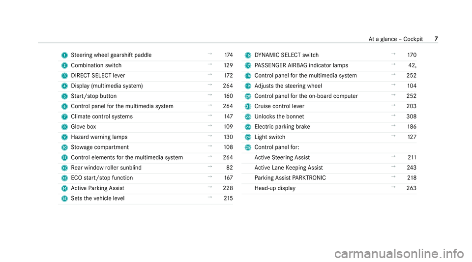
1
Steering wheel gearshift paddle →
174
2 Combination swit ch →
12 9
3 DIRECT SELECT le ver →
172
4 Displ ay(multimedia sy stem) →
264
5 Start/ stop button →
16 0
6 Control panel forth e multimedia sy stem →
264
7 Climate control sy stems →
147
8 Glovebox →
109
9 Haza rdwa rning lamps →
13 0
A Stow age compartment →
108
B Control elements forth e multimedia sy stem →
264
C Rear wind ow roller sunblind →
82
D ECO start/ stop function →
167
E Active Parking Assist →
228
F Sets theve hicle le vel →
215 G
DYNA MIC SELECT switch →
17 0
H PASSENGER AIRB AGindicator lamps →
42,
I Cont rol panel forth e multimedia sy stem →
252
J Adjusts thesteering wheel →
104
K Control panel forth e on-board computer →
252
L Cruise control le ver →
203
M Unloc ksthe bonn et →
308
N Electric parking brake →
186
O Light switch →
127
P Control panel for:
Ac tive Steering Assist →
211
Ac tive Lane Keeping Assist →
24 3
Pa rking Assist PARKTRONIC →
218
Head-up display →
263 At
aglance – Cockpit 7
Page 12 of 497
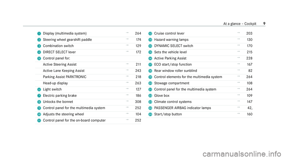
1
Displ ay(multimedia sy stem) →
264
2 Steering wheel gearshift paddle →
174
3 Combination swit ch →
12 9
4 DIRECT SELECT le ver →
172
5 Control panel for:
Ac tive Steering Assist →
211
Ac tive Lane Keeping Assist →
24 3
Pa rking Assist PARKTRONIC →
218
Head-up display →
263
6 Light switch →
127
7 Electric pa rking brake →
186
8 Unloc ksthe bonn et →
308
9 Control panel forth e multimedia sy stem →
252
A Adjusts thesteering wheel →
104
B Control panel forth e on-board computer →
252 C
Cruise control le ver →
203
D Hazard warning lamps →
13 0
E DYNA MIC SELECT switch →
17 0
F Sets theve hicle le vel →
215
G Active Parking Assist →
228
H ECO start/ stop function →
167
I Rear wind ow roller sunblind →
82
J Cont rol elements forth e multimedia sy stem →
264
K Stow age compartment →
108
L Control panel forth e multimedia sy stem →
264
M Glovebox →
109
N Climate cont rol sy stems →
147
O PASSENGER AIRB AGindicator lamps →
42,
P Start/ stop button →
16 0 At
aglance – Cockpit 9
Page 14 of 497
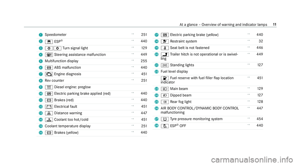
1
Speedom eter →
251
2 ÷ ESP®
→
440
3 #! Turn signal light →
12 9
4 Ð Steering assis tance malfunction →
449
5 Multifunction display →
255
6 ! ABS malfunction →
440
7 ; Engine diagnosis →
451
8 Rev counter →
251
9 % Diesel engine: preglow
A ! Electric parking brake applied (red) →
440
B J Brakes (red) →
440
C # Electrical fault →
451
D · Distance warning →
447
E ? Coolant too hot/cold →
451
F Coolant temp erature display →
251
G J Brakes (yellow) →
440 H
! Electric pa rking brake (yellow) →
440
I 6 Restra int sy stem →
32
J ü Seat belt is not fastened →
446
K j Trailer hit chis not operational or is swivel‐
ling →
449
L T Standing lights →
127
M Fuel le vel display
8 Fuelreser vewith fuel filler flap location
indicator →
451
N K Main beam →
12 9
O L Dipped beam →
127
P R Rear fog light →
12 8
Q AIR BODY CONTROL/DYNAMIC BODY CONTROL
malfunctioning →
447
R h Tyre pressure monitoring sy stem →
454
S å ESP®
OFF →
440 At
aglance – Overview of warning and indicator lamps 11
Page 16 of 497
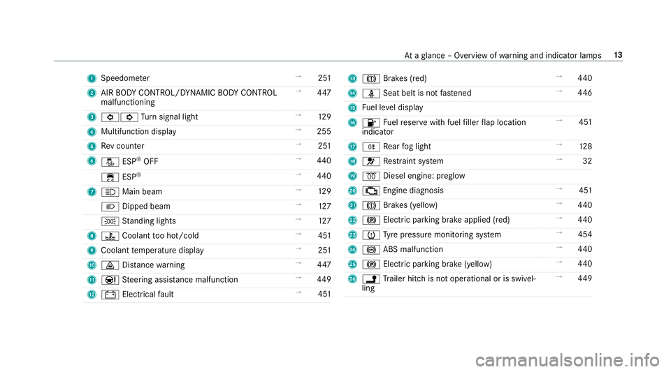
1
Speedom eter →
251
2 AIR BODY CONTROL/DYNAMIC BODY CONTROL
malfunctioning →
447
3 #! Turn signal light →
12 9
4 Multifunction display →
255
5 Rev counter →
251
6 å ESP®
OFF →
440
÷ ESP®
→
440
7 K Main beam →
12 9
L Dipped beam →
127
T Standing lights →
127
8 ? Coolant too hot/cold →
451
9 Coolant temp erature display →
251
A · Distance warning →
447
B Ð Steering assis tance malfunction →
449
C # Electrical fault →
451 D
J Brakes (red) →
440
E ü Seat belt is not fastened →
446
F Fuel le vel display
G 8 Fuelreser vewith fuel filler flap location
indicator →
451
H R Rear fog light →
12 8
I 6 Restra int sy stem →
32
J % Diesel engine: preglow
K ; Engine diagnosis →
451
L J Brakes (yellow) →
440
M ! Electric pa rking brake applied (red) →
440
N h Tyre pressure monitoring sy stem →
454
O ! ABS malfunction →
440
P ! Electric pa rking brake (yellow) →
440
Q j Trailer hit chis not operational or is swivel‐
ling →
449 At
aglance – Overview of warning and indicator lamps 13
Page 18 of 497
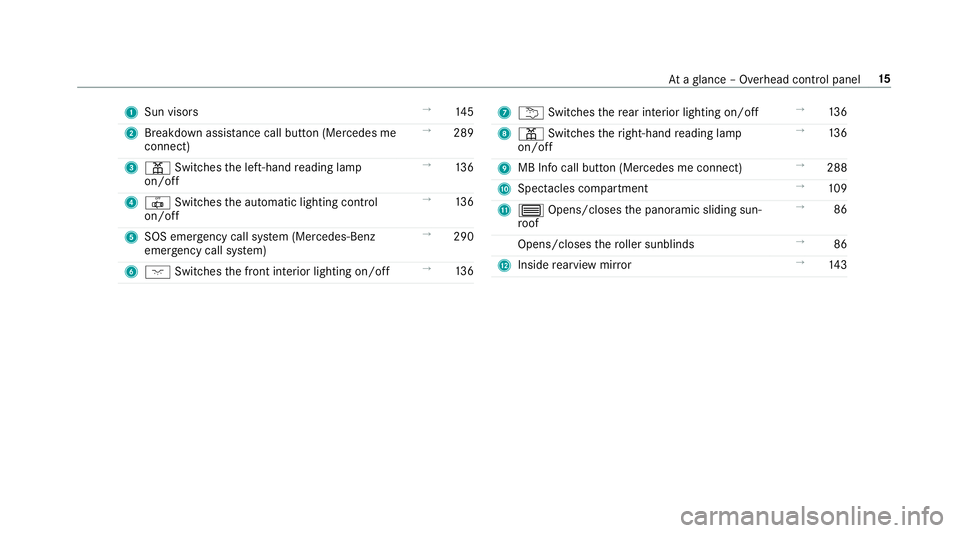
1
Sun visors →
14 5
2 Breakdown assis tance call button (Mercedes me
connect) →
289
3 p Switches the left-hand reading lamp
on/off →
13 6
4 | Switches the automatic lighting control
on/off →
13 6
5 SOS emergency call sy stem (Mercedes-Benz
emer gency call sy stem) →
290
6 c Switches the front interior lighting on/off →
13 6 7
u Switches there ar interior lighting on/off →
13 6
8 p Switches theright-hand reading lamp
on/off →
13 6
9 MB Info call button (Mercedes me connect) →
288
A Spectacles compartment →
109
B 3 Opens/closes the panoramic sliding sun‐
ro of →
86
Opens/closes thero ller sunblinds →
86
C Inside rearview mir ror →
14 3 At
aglance – Overhead control panel 15
Page 31 of 497
ve
hicle in a compact form , e.g. thero uting of the
electric lines.
Fu rther information can be obtained at http://
www.mercedes-benz.de/qr-code. Ve
hicle data storage Information from electronic control units
Electronic control units are
fitted in your vehicle.
Some of these are necessary forth e safe opera‐
tion of your vehicle, while some assist you when
driving (driver assis tance sy stems). In addition,
yo ur vehicle pr ovides con venience and enter tain‐
ment functions, which are also made possible by
electronic control units.
Elect ronic control units contain da tamemories
which cantemp orarily or permanently store
te ch nical information about theve hicle's operat‐
ing status, component loads, main tenance
re qu irements and tech nical events or faults. In
general, this information documents thest ate
of a component part, a module, a sy stem or the
sur roundings such as:
R operating statuses of sy stem components
(e.g. fluid le vels, battery status, tyre pres‐
sure)
R status messages concerning theve hicle and
its individual components (e.g. number of
wheel revo lutions/speed, decele ration, lat‐
eral acceleration, display of thefa stened seat
belts)
R malfunctions or defects in impor tant sy stem
components (e.g. lights, brakes)
R information on vehicle damage events
R system reactions in special driving situations
(e.g. airbag deployment, inter vention of sta‐
bility control sy stems)
R ambient conditions (e.g. temp erature, rain
sensor)
In addition toprov iding the actual control unit
function, this data assists the manufacturer in
de tecting and rectifying faults and optimising
ve hicle functions. The majority of this data is te
mp orary and is only processed in theve hicle
itself. Only a small portion of the data is stored
in theeve nt or fault memor y.
When your vehicle is serviced, tech nical da ta
from theve hicle can be read out byservice net‐
wo rkemplo yees or third parties. Services
include repair services, maintenance processes,
wa rranty events and quality assurance meas‐
ures, forex ample. The read out is per form ed via
th e legally prescribed port for OBD ("on-board
diagnostics") in theve hicle. The respective
service network locations or third parties col‐
lect, process and use the data. They document
te ch nical statuses of theve hicle, assist in find‐
ing faults and impr oving quality and are trans‐
mit tedto the manufacturer, if necessar y.Fu r‐
th ermore, the manufacturer is subject toprod‐
uct liability. Forth is, the manufacturer requ ires
te ch nical da tafrom vehicles.
Fa ult memories in theve hicle can be reset by a
service outlet as part of repair or maintenance
wo rk.
They can enter data into theve hicle's con veni‐
ence and inf otainment functions themselves as
part of the selected equipment. 28
General no tes
Page 32 of 497
This includes,
forex ample:
R multimedia data such as music, films or pho‐
to sfo r playback in an integrated multimedia
sy stem
R address book data for use in connection with
an integrated hands-free sy stem or an inte‐
grated navigation sy stem
R entered navigation destinations
R data about the use of Internet services
This data can be stored locally in theve hicle or
is located on a device which you ha veconnected
to theve hicle. If this data is stored in theve hi‐
cle, you can dele teit at any time. This data can
only be transmitted tothird parties upon your
requ est with particular rega rd tothe scope of
use of online services according to your selected
settings.
Yo u can store or change con venience settings/
individualisations in theve hicle at any time.
Depending on the equipment, this includes, for
ex ample:
R seat and steering wheel position settings
R suspension and climate control settings R
individualisations such as interior lighting
If yo ur vehicle is accordingly equipped, you can
connect your smartphone or ano ther mobile end
device totheve hicle. You can cont rolth em via
th e control elements integrated in your vehicle.
Images and audio from the smartphone can be
output via the multimedia sy stem. Cer tain infor‐
mation is simultaneously transmitted to your
smartphone.
Depending on there spective integration type,
th is includes, forex ample:
R general vehicle information
R position data
This enables the use of selected smartphone
Apps, e.g. navigation or music playbac k.There is
no fur ther interaction between the smartphone
and theve hicle; in particular, vehicle data is not
directly accessible. The type of fur ther data pro‐
cessing is de term ined bythe pr ovider of the App
used. The respective App and your smartphone's
operating sy stem de term ine whe ther changes
can be made tothe settings and which settings
can be changed. Service pr
oviders Wire
less network connection
If yo ur vehicle has a wireless network connec‐
tion, it enables data tobe exc hanged between
yo ur vehicle and additional sy stems. The wire‐
less network connection is enabled via theve hi‐
cle's transmission and reception unit or via con‐
nected mobile end devices (e.g. sma rtphones).
Online functions can be used via the wireless
network connection. This includes online serv‐
ices and applications/Apps pr ovided bythe
manufacturer or other pr oviders.
Manu factu rer's se rvices
The manufacturer describes there spective func‐
tions and cor responding legal data pr otection
information when suitable forth e manufacturer's
online services. Personal data may be used for
th e pr ovision of online services. Data is
exc hanged via a secure connection, e.g. tothe
manufacturer's designated IT sy stems. Personal
data is collected, processed and used via the
pr ov ision of services exclusively on the basis of
legal permissions or with prior consent. General no
tes29
Page 35 of 497
Re
stra int sy stem functionality When
the ignition is switched on, a sy stem self-
te st is per form ed, during which the6
re stra int sy stem warning lamp lights up. It goes
out no later than a few seconds af terth eve hicle
is star ted. The components of there stra int sys‐
te m are then functional. Malfunctioning
restra int sy stem A malfunction has occur
red in there stra int sys‐
te m if:
R The 6 restra int sy stem warning lamp
does not light up when the ignition is
switched on.
R The 6 restra int sy stem warning lamp
lights up continuously or repeatedly during a
journe y. &
WARNING Risk of inju ryor fata l injury
due toa malfunction in there stra int sys‐
tem
If th ere stra int sy stem is malfunctioning,
re stra int sy stem components may be trig‐
ge red unintentionally or might not be trig‐
ge red at all in theeve nt of an accident. This
may af fect the seat belt tensioner or airbag,
fo rex ample. #
Have there stra int sy stem checked and
re paired immediately at a qualified spe‐
cialist workshop. Fu
nction of there stra int sy stem in an acci‐
dent How
there stra int sy stem works is de term ined by
th e se verity of the impact de tected and the type
of accident anticipated:
R Frontal impact
R Rear impact
R Side impact
R Rollover The activation
thre sholds forth e components of
th ere stra int sy stem are de term ined based on
th eev aluation of the sensor values measured at
va rious points in theve hicle. This process is pre-
em ptive in nature. The triggering/deployment of
th e components of there stra int sy stem should
ta ke place in good time at thest art of the colli‐
sion.
Fa ctors whi chcan only be seen and measu red
af te r a collision has occur red cann otplay a deci‐
sive role in airbag deployment, nor do they pro‐
vide an indication of airbag deployment.
The vehicle may be deformed significantly with‐
out an airbag being deplo yed. This is the case if
only parts which are relatively easily deformed
are af fected and thera te ofvehicle deceleration
is not high. Con versely, an airbag may be
deplo yedev en though theve hicle suf fers only
minor deformation. If very rigid vehicle parts
such as longitudinal members are hit, forex am‐
ple, theve hicle deceleration may be high enough
fo rth is to happen. 32
Occupant saf ety