mirror controls MERCEDES-BENZ E-CLASS WAGON 2001 W210 User Guide
[x] Cancel search | Manufacturer: MERCEDES-BENZ, Model Year: 2001, Model line: E-Class WAGON, Model: MERCEDES-BENZ E-Class WAGON 2001 W210Pages: 345, PDF Size: 16.08 MB
Page 86 of 345
83 Rear view mirrors
Te ch n ica l
data Instruments
and controlsOperationDrivingInstrument
cluster displayPractical hints Car care Index Exterior rear view mirrors
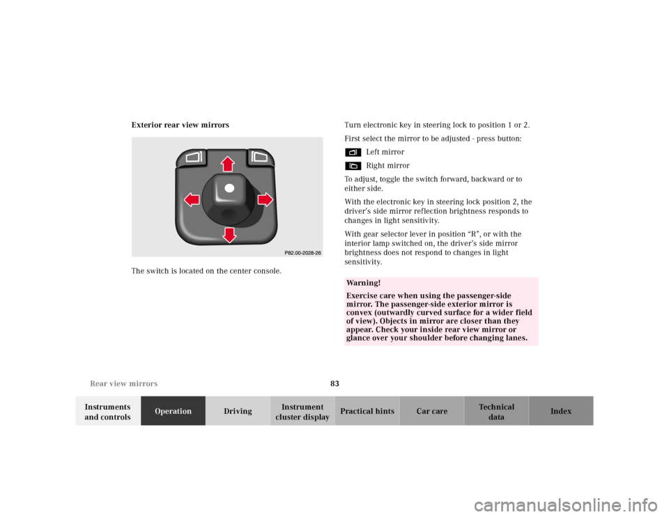
The switch is located on the center console.Turn electronic key in steering lock to position 1 or 2.
First select the mirror to be adjusted - press button:
%Left mirror
&Right mirror
To adjust, toggle the switch forward, backward or to
either side.
With the electronic key in steering lock position 2, the
driver’s side mirror reflection brightness responds to
changes in light sensitivity.
With gear selector lever in position “R”, or with the
interior lamp switched on, the driver’s side mirror
brightness does not respond to changes in light
sensitivity.
Wa r n i n g !
Exercise care when using the passenger-side
mirror. The passenger-side exterior mirror is
convex (outwardly curved surface for a wider field
of view). Objects in mirror are closer than they
appear. Check your inside rear view mirror or
glance over your shoulder before changing lanes.
Page 87 of 345
84 Rear view mirrors
Te ch n ica l
data Instruments
and controlsOperationDrivingInstrument
cluster displayPractical hints Car care Index
Note:
The exterior mirrors have electrically heated glass. The
heater switches on automatically, depending on outside
temperature.
If an exterior mirror housing is forcibly pivoted from its
normal position, it must be repositioned by applying
firm pressure until it snaps into place.Important!
Electrolyte drops coming into contact with the vehicle
paint finish can only be completely removed while in
their liq uid state, by applying plenty of water.
Storing mirror positions in memory
The exterior rear view mirror positions are stored in
memory with the seat / head restraint / steering column
position and can be recalled when necessary, see
page 47.
Wa r n i n g !
In the case of an accident liquid electrolyte may
escape the mirror housing when the mirror glass
breaks.Electrolyte has an irritating effect. Do not allow the
liquid come into contact with eyes, skin, clothing,
or respiratory system. In cases it does, immediately
flush affected area with water, and seek medical
help if necessary.
Page 88 of 345
85 Rear view mirrors
Te ch n ica l
data Instruments
and controlsOperationDrivingInstrument
cluster displayPractical hints Car care Index Parking position
The passenger-side exterior mirror can be adjusted and
programmed to assist the driver during parking
maneuvers (e.g. to observe the curb or other objects
close to the vehicle).
With electronic key in steering lock position 2, and the
exterior rear view mirror switch in the passenger-side
position, the passenger-side mirror will be turned
downward when placing the gear selector lever in
“R” Reverse.
The mirror position can now be adjusted as desired.
At speeds above approximately 6 mph (10 km / h), upon
shifting gear selector lever from “R” Reverse, or upon
pressing the driver’s side mirror button, the passenger-
side mirror will return to its previous position.One passenger-side mirror position can be stored in
memory. To do so:
1. Turn electronic key to steering lock position 2.
The vehicle must be stationary.
2. Select passenger-side mirror and adjust the mirror
to view the curb.
3. Press green memory button located in switch cluster
for driver seat, see page 47.
4. Within 3 seconds pull the mirror toggle switch
rearward. The mirror should not move.
Repeat the memory procedure if the mirror moves.
5. Select driver side mirror. The passenger-side mirror
will return to its previous position.
Page 163 of 345
160 Interior equipment
Te ch n ica l
data Instruments
and controlsOperationDrivingInstrument
cluster displayPractical hints Car care Index
Sun visors
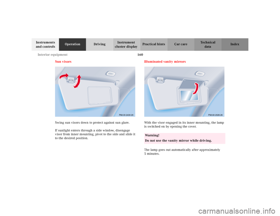
Swing sun visors down to protect against sun glare.
If sunlight enters through a side window, disengage
visor from inner mounting, pivot to the side and slide it
to the desired position.Illuminated vanity mirrors
With the visor engaged in its inner mounting, the lamp
is switched on by opening the cover.
The lamp goes out automatically after approximately
5minutes.
P68.00-2430-26
Wa r n i n g !
Do not use the vanity mirror while driving.
P68.60-2026-26
Page 183 of 345
180 Garage door opener
Te ch n ica l
data Instruments
and controlsOperationDrivingInstrument
cluster displayPractical hints Car care Index
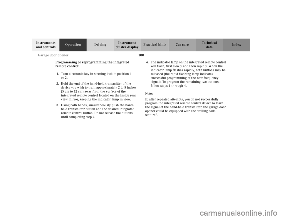
Programming or reprogramming the integrated
remote control:
1. Turn electronic key in steering lock to position 1
or 2.
2. Hold the end of the hand-held transmitter of the
device you wish to train approximately 2 to 5 inches
(5 cm to 12 cm) away from the surface of the
integrated remote control located on the inside rear
view mirror, keeping the indicator lamp in view.
3. Using both hands, simultaneously push the hand-
held transmitter button and the desired integrated
remote control button. Do not release the buttons
until completing step 4.4. The indicator lamp on the integrated remote control
will flash, first slowly and then rapidly. When the
indicator lamp flashes rapidly, both buttons may be
released (the rapid flashing lamp indicates
successful programming of the new frequency
signal). To program the remaining two buttons,
follow ste ps 1 through 4.
Note:
If, after repeated attempts, you do not successfully
program the integrated remote control device to learn
the signal of the hand-held transmitter, the garage door
opener could be equipped with the “rolling code
feature”.
Page 190 of 345
187 Tele Aid
Te ch n ica l
data Instruments
and controlsOperationDrivingInstrument
cluster displayPractical hints Car care Index Important!
Always make sure that the indicator lamps in the
“SOS” button, in the “Roadside Assistance” button and
in the “Information” button do not remain illuminated
constantly in red and the message “TELE AID – VISIT
WORKSHOP” is not displayed in the multifunction
display after the system self check.
If a malfunction is indicated as outlined above, have the
system checked at the nearest Mercedes-Benz Center as
soon as possible.
Emergency calls
An emergency call is initiated automatically:
•following an accident in which the Emergency
Tensioning Retractors (ETR’s) or airbags deploy,
•if the antitheft alarm or the tow away alarm stays on
for more than 20 seconds, see pages 41 and 43.
An emergency call can also be initiated manually by
opening the cover next to the inside rear view mirror
labeled “SOS”, then pressing the button (for longer than
2 seconds) located under the cover. See below for
instructions on initiating an emergency call manually.Once the emergency call is in progress, the indicator
lamp in the “SOS” button will begin to f lash. The
message “EMERGENCY CALL – CONNECTING CALL”
appears in the multifunction display. When the
connection is established, the message “EMERGENCY
CALL – CALL CONNECTED” appears in the
multifunction display. All information relevant to the
emergency, such as the location of the vehicle
(determined by the GPS satellite location system),
vehicle model, identification number and color are
generated.
A voice connection between the Response Center and
the occupants of the vehicle will be established
automatically soon after the emergency call has been
initiated. When a voice connection is established the
audio system mutes and the message “TELE AID –
EMERGENCY CALL ACTIVE” appears in the
multifunction display. The Response Center will attempt
to determine more precisely the nature of the accident
provided they can speak to an occupant of the vehicle.
Page 300 of 345
297 Exterior lamps
Te ch n ica l
data Instruments
and controlsOperation DrivingInstrument
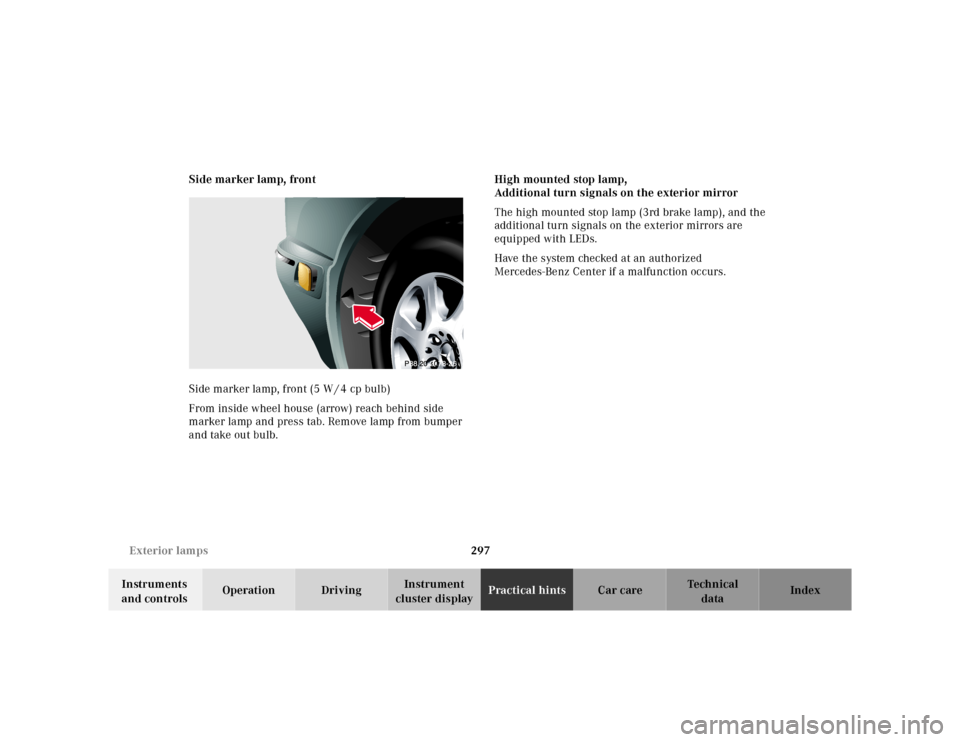
cluster displayPractical hintsCar care Index Side marker lamp, front
Side marker lamp, front (5 W / 4 cp bulb)
From inside wheel house (arrow) reach behind side
marker lamp and press tab. Remove lamp from bumper
and take out bulb.High mounted stop lamp,
Additional turn signals on the exterior mirror
The high mounted stop lamp (3rd brake lamp), and the
additional turn signals on the exterior mirrors are
equipped with LEDs.
Have the system checked at an authorized
Mercedes-Benz Center if a malfunction occurs.
Page 313 of 345
310 Cleaning and care of the vehicle
Te ch n ica l
data Instruments
and controlsOperation DrivingInstrument
cluster displayPractical hintsCar careIndex
Engine cleaning
Prior to cleaning the engine compartment make sure to
protect electrical components and connectors from the
intrusion of water and cleaning agents.
Corrosion protection, such as MB Anticorrosion Wax
should be applied to the engine compartment after
every engine cleaning. Before applying, all control
linkage bushings and joints should be lubricated. The
poly-V-belt and all pulleys should be protected from any
wax.
Ve h i c l e w a s h i n g
Do not use hot water or wash your vehicle in direct
sunlight. Use only a mild car wash detergent, such as
Mercedes-Benz approved Car Shampoo.
Thoroughly spray the vehicle with a diffused jet of
water. Direct only a very weak spray towards the
ventilation intake. Use plenty of water and rinse the
sponge and chamois frequently.
Rinse with clear water and thoroughly wipe dry with a
chamois. Do not allow cleaning agents to dry on the
finish.Due to the width of the vehicle, prior to running the
vehicle through an automatic car wash, fold back the
outside mirrors to prevent them from getting damaged.
In the winter, thoroughly remove all traces of road salt
as soon as possible.
When washing the underbody, do not forget to clean the
inner sides of the wheels.
Ornamental moldings
For regular cleaning and care of very dirty chrome-
plated parts, use a chrome cleaner.
Headlamps, taillamps, turn signal lenses
Use a mild car wash detergent, such as Mercedes-Benz
approved Car Shampoo, with plenty of water.
To prevent scratches, never apply strong force and use
only a soft, non-scratchy cloth when cleaning the lenses.
Do not attempt to wipe dirty lenses with a dry cloth or
sponge.
Page 336 of 345
333
Te ch n ica l
data Instruments
and controlsOperation DrivingInstrument
cluster displayPractical hints Car careIndex
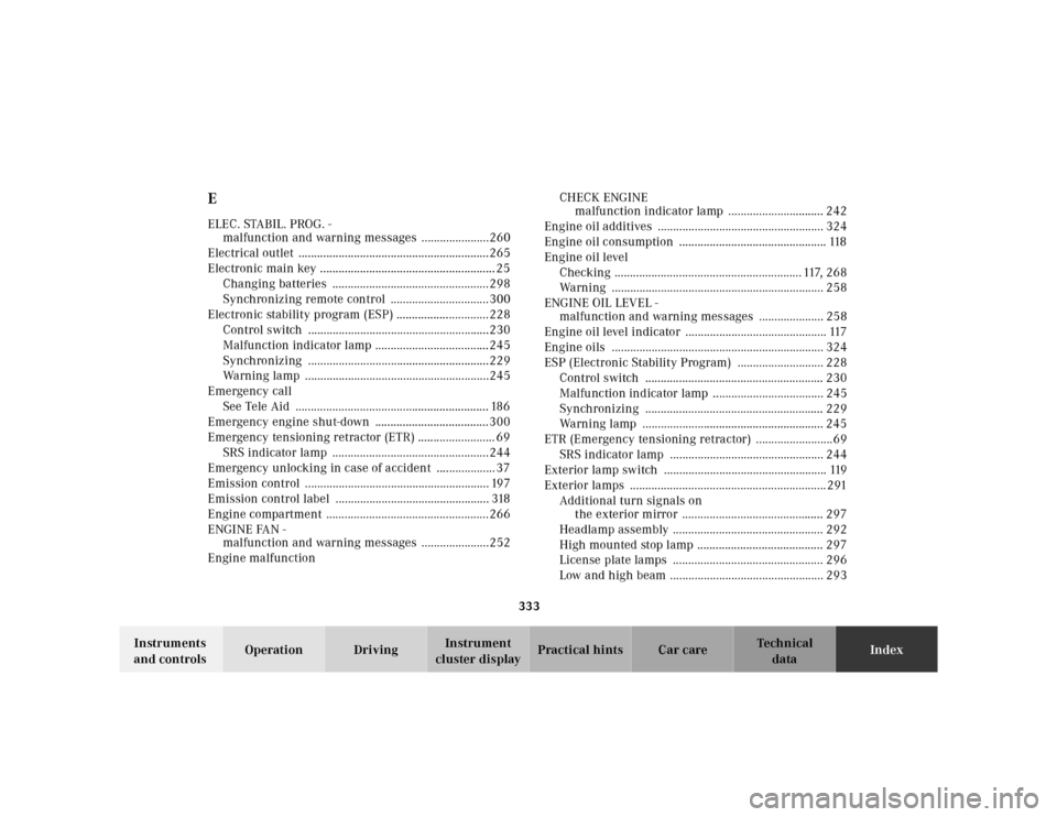
EELEC. STABIL. PROG. -
malfunction and warning messages ......................260
Electrical outlet ..............................................................265
Electronic main key ......................................................... 25
Changing batteries ...................................................298
Synchronizing remote control ................................300
Electronic stability program (ESP) ..............................228
Control switch ...........................................................230
Malfunction indicator lamp .....................................245
Synchronizing ...........................................................229
Warning lamp ............................................................245
Emergency call
See Tele Aid ............................................................... 186
Emergency engine shut-down .....................................300
Emergency tensioning retractor (ETR) ......................... 69
SRS indicator lamp ...................................................244
Emergency unlocking in case of accident ................... 37
Emission control ............................................................ 197
Emission control label .................................................. 318
Engine compartment .....................................................266
ENGINE FAN -
malfunction and warning messages ......................252
Engine malfunctionCHECK ENGINE
malfunction indicator lamp ............................... 242
Engine oil additives ...................................................... 324
Engine oil consumption ................................................ 118
Engine oil level
Checking ............................................................. 117, 268
Warning ..................................................................... 258
ENGINE OIL LEVEL -
malfunction and warning messages ..................... 258
Engine oil level indicator .............................................. 117
Engine oils ..................................................................... 324
ESP (Electronic Stability Program) ............................ 228
Control switch .......................................................... 230
Malfunction indicator lamp .................................... 245
Synchronizing .......................................................... 229
Warning lamp ........................................................... 245
ETR (Emergency tensioning retractor) .........................69
SRS indicator lamp .................................................. 244
Exterior lamp switch ..................................................... 119
Exterior lamps ................................................................ 291
Additional turn signals on
the exterior mirror .............................................. 297
Headlamp assembly ................................................. 292
High mounted stop lamp ......................................... 297
License plate lamps ................................................. 296
Low and high beam .................................................. 293
Page 338 of 345
335
Te ch n ica l
data Instruments
and controlsOperation DrivingInstrument
cluster displayPractical hints Car careIndex
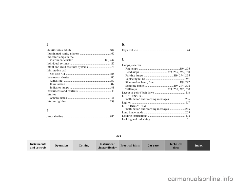
IIdentification labels ....................................................... 317
Illuminated vanity mirrors ........................................... 160
Indicator lamps in the
instrument cluster ............................................. 88, 242
Individual settings ..........................................................110
Infant and child restraint systems ................................ 78
Information call
See Tele Aid ............................................................... 186
Instrument cluster ........................................................... 86
Activating ..................................................................... 89
Illumination ................................................................. 89
Indicator lamps ........................................................... 88
Instruments and controls ............................................... 18
Interior
General notes ............................................................. 161
Interior lighting ............................................................. 159JJump starting ..................................................................285
KKeys, vehicle .....................................................................24LLamps, exterior
Fog lamps ...........................................................119, 295
Headlamps ........................................ 119, 255, 292, 310
Parking lamps ...........................................119, 294, 295
Replacing bulbs ......................................................... 291
Side marker lamp, front ...................................119, 297
Standing lamps .........................................119, 294, 295
Taillamps .......................................... 119, 255, 295, 310
Layout of poly-V-belt drive ............................................ 318
LIGHT SENSOR -
malfunction and warning messages ..................... 256
Lighter ............................................................................. 167
LIGHTING SYSTEM -
malfunction and warning messages ..................... 255
Limp home mode ........................................................... 209
Loading instructions ...................................................... 176
Locking and unlocking .................................................... 31