parking brake MERCEDES-BENZ E-CLASS WAGON 2001 W210 Owner's Manual
[x] Cancel search | Manufacturer: MERCEDES-BENZ, Model Year: 2001, Model line: E-Class WAGON, Model: MERCEDES-BENZ E-Class WAGON 2001 W210Pages: 345, PDF Size: 16.08 MB
Page 6 of 345

3 Contents
DrivingControl and operation of radio
transmitters ............................... 184
The first 1 000 miles
(1 500 km) ................................. 185
Maintenance ................................... 185
Tele Aid............................................ 186
Catalytic converter......................... 196
Emission control ............................ 197
Steering lock ................................... 198
Starting and turning off
the engine .................................. 200
Automatic transmission................ 201
Parking brake ................................. 210
Driving instructions ...................... 211
Drive sensibly -
Save Fuel ..................................... 211
Drinking and Driving ................ 211
Pedals ........................................... 211
Power assistance ........................ 212
Brakes .......................................... 212
Driving off ................................... 213
Parking ........................................ 213Tires ..............................................214
Snow chains ................................ 216
Winter driving instructions ......217
Block heater .................................218
Deep water ...................................219
Passenger compartment ............219
Traveling abroad ......................... 219
Cruise control ................................ 220
Brake assist system
(BAS)........................................... 223
Antilock brake system
(ABS) .......................................... 225
Four wheel electronic
traction system (4MATIC) ....... 227
Electronic stability program
(ESP) ........................................... 228
Parking assist (Parktronic) .......... 232
What you should know
at the gas station ...................... 237
Check regularly and before
a long trip .................................. 239
Instrument cluster displayMalfunction and indicator
lamps in the
instrument cluster .................... 242
On-board
diagnostic system .......................242
Check engine malfunction
indicator lamp .............................242
Brake warning lamp ..................243
Supplemental restraint
system (SRS)
indicator lamp .............................244
Fuel reserve and fuel cap
placement warning ....................244
Electronic stability program
(ESP) — warning lamp ...............245
BAS / ESP malfunction
indicator lamp .............................245
ABS malfunction
indicator lamp .............................245
Seat belt warning lamp .............246
Malfunction and indicator
lamp in the center console ...... 246
Page 7 of 345

4 Contents
AIRBAG OFF
indicator lamp .............................246
Malfunction and warning
messages in the
multifunction display ............... 247
DISPLAY DEFECTIVE ................248
BATTERY / ALTERNATOR .........249
ABS-SYSTEM ...............................250
BRAKE ASSIST ...........................250
BRAKE LINING WEAR .............. 251
BRAKE FLUID ............................. 251
PARKING BRAKE .......................252
ENGINE FAN ...............................252
COOLANT (coolant level) ..........253
COOLANT TEMP. (coolant
temperature) ...............................254
LIGHTING SYSTEM ....................255
LIGHT SENSOR ...........................256
REMOVE KEY .............................256
TELE AID .....................................257
STEERING GEAR OIL .................257
ENGINE OIL LEVEL ...................258
WASHER FLUID ..........................259ELEC. STABIL. PROG.
(Electronic stability program) . 260
Practical hintsFirst aid kit ..................................... 262
Fuses ............................................... 263
Electrical outlet.............................. 265
Hood ................................................ 266
Checking engine oil level............. 268
Automatic transmission
fluid level ................................... 269
Coolant level................................... 269
Adding coolant ........................... 270
Windshield and headlamp
washer system .......................... 271
Windshield and headlamp
washer fluid mixing ratio .........271
Spare wheel, vehicle tools............ 272
Vehicle jack .................................... 273
Wheels ............................................ 274
Tire replacement ........................274
Rotating wheels ......................... 275
Spare wheel..................................... 276
Spare wheel bolts .......................276Changing wheels ........................... 277
Tire inflation pressure .................. 282
Battery ............................................. 283
Jump starting .................................. 285
Towing the vehicle ......................... 288
Transmission selector lever,
manually unlocking .................. 290
Exterior lamps ................................ 291
Headlamp assembly ...................292
Taillamp assemblies ..................295
Changing batteries in the
electronic main key .................. 298
Synchronizing
remote control ............................300
Emergency engine
shut-down................................... 300
Emergency operation of
sliding / pop-up roof ................. 301
Manual release for
fuel filler flap ............................. 302
Replacing wiper blade insert ....... 302
Roof rack ......................................... 305
Page 22 of 345
19 Instruments and controls
Te ch n ica l
data Instruments
and controlsOperation DrivingInstrument
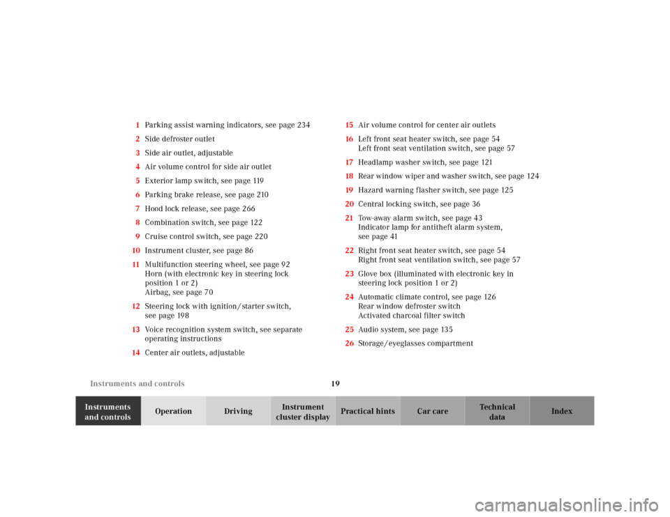
cluster displayPractical hints Car care Index 1Parking assist warning indicators, see page 234
2Side defroster outlet
3Side air outlet, adjustable
4Air volume control for side air outlet
5Exterior lamp switch, see page 119
6Parking brake release, see page 210
7Hood lock release, see page 266
8Combination switch, see page 122
9Cruise control switch, see page 220
10Instrument cluster, see page 86
11Multifunction steering wheel, see page 92
Horn (with electronic key in steering lock
position 1 or 2)
Airbag, see page 70
12Steering lock with ignition / starter switch,
see page 198
13Voice recognition system switch, see separate
operating instructions
14Center air outlets, adjustable15Air volume control for center air outlets
16Left front seat heater switch, see page 54
Left front seat ventilation switch, see page 57
17Headlamp washer switch, see page 121
18Rear w ind ow w iper a nd washer sw itch, se e page 124
19Hazard warning flasher switch, see page 125
20Central locking switch, see page 36
21Tow-away alarm switch, see page 43
Indicator lamp for antitheft alarm system,
seepage41
22Right front seat heater switch, see page 54
Right front seat ventilation switch, see page 57
23Glove box (illuminated with electronic key in
steering lock position 1 or 2)
24Automatic climate control, see page 126
Rear window defroster switch
Activated charcoal filter switch
25Audio system, see page 135
26Storage / eyeglasses compartment
Page 91 of 345
88 Instrument cluster
Te ch n ica l
data Instruments
and controlsOperationDrivingInstrument
cluster displayPractical hints Car care Index
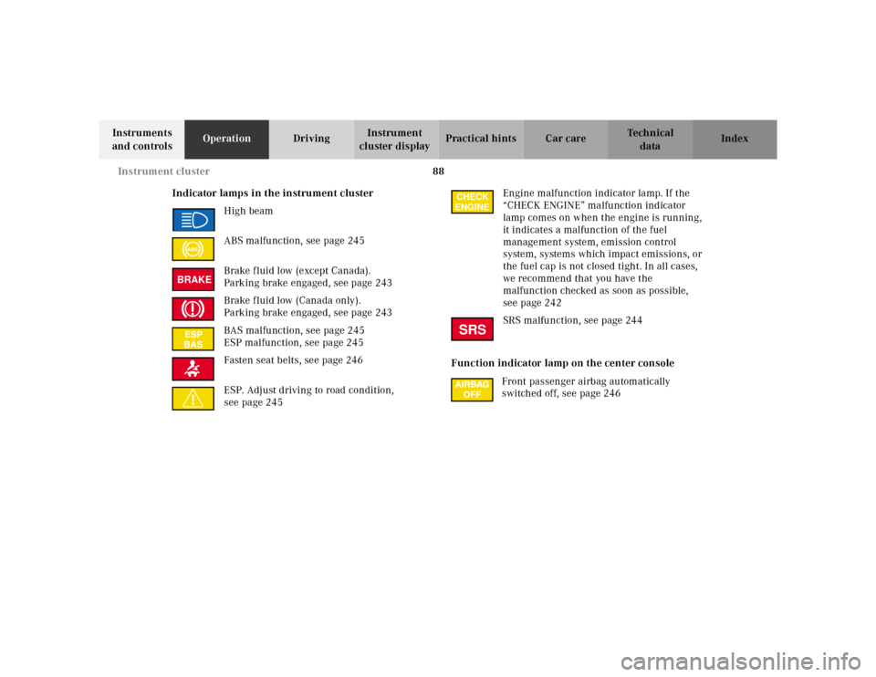
Indicator lamps in the instrument cluster
High beam
ABS malfunction, see page 245
Brake fluid low (except Canada).
Parking brake engaged, see page 243
Brake fluid low (Canada only).
Parking brake engaged, see page 243
BAS malfunction, see page 245
ESP malfunction, see page 245
Fasten seat belts, see page 246
ESP. Adjust driving to road condition,
see page 245Engine malfunction indicator lamp. If the
“CHECK ENGINE” malfunction indicator
lamp comes on when the engine is running,
it indicates a malfunction of the fuel
management system, emission control
system, systems which impact emissions, or
the fuel cap is not closed tight. In all cases,
we recommend that you have the
malfunction checked as soon as possible,
see page 242
SRS malfunction, see page 244
Function indicator lamp on the center console
Front passenger airbag automatically
switched off, see page 246
ABSBRAKE
CHECK
ENGINESRS
Page 168 of 345
165 Interior equipment
Te ch n ica l
data Instruments
and controlsOperationDrivingInstrument
cluster displayPractical hints Car care Index Ashtrays
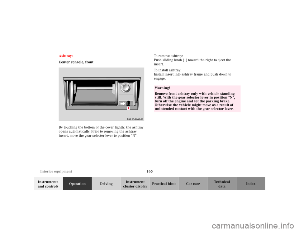
Center console, front
By touching the bottom of the cover lightly, the ashtray
opens automatically. Prior to removing the ashtray
insert, move the gear selector lever to position “N”.To remove ashtray:
Push sliding knob (1) toward the right to eject the
insert.
To i n st a l l a s h t r ay :
Install insert into ashtray frame and push down to
engage.
Wa r n i n g !
Remove front ashtray only with vehicle standing
still. With the gear selector lever in position “N”,
turn off the engine and set the parking brake.
Otherwise the vehicle might move as a result of
unintended contact with the gear selector lever.
Page 186 of 345
183 Contents - Driving
Te ch n ica l
data Instruments
and controlsOperationDrivingInstrument
cluster displayPractical hints Car care Index
DrivingControl and operation of radio
transmitters ............................... 184
The first 1 000 miles
(1 500 km) ................................. 185
Maintenance ................................... 185
Tele Aid............................................ 186
Catalytic converter......................... 196
Emission control ............................ 197
Steering lock ................................... 198
Starting and turning off
the engine .................................. 200
Automatic transmission................ 201
Parking brake ................................. 210Driving instructions....................... 211
Drive sensibly -
Save Fuel ...................................... 211
Drinking and Driving ................ 211
Pedals ........................................... 211
Power assistance .........................212
Brakes ...........................................212
Driving off ....................................213
Parking .........................................213
Tires ..............................................214
Snow chains ................................ 216
Winter driving instructions ......217
Block heater .................................218
Deep water ...................................219
Passenger compartment ............219
Traveling abroad ......................... 219Cruise control ................................. 220
Brake assist system
(BAS) ........................................... 223
Antilock brake system
(ABS) ........................................... 225
Four wheel electronic
traction system
(4MATIC) .................................... 227
Electronic stability
program
(ESP) ........................................... 228
Parking assist (Parktronic) .......... 232
What you should know
at the gas station ....................... 237
Check regularly and
before a long trip....................... 239
Page 203 of 345
200 Starting and turning off the enging
Te ch n ica l
data Instruments
and controlsOperationDrivingInstrument
cluster displayPractical hints Car care Index
Starting and turning off the engine
Before Starting
Ensure that parking brake is engaged and that selector
lever is in position “P” or “N”. Turn electronic key in
steering lock to position 2.
Starting
Do not depress accelerator.
Briefly turn electronic key in steering lock clockwise to
the stop and release. The starter will engage until the
engine is running.
If engine will not run, and the starting procedure stops,
turn electronic key completely to the left and repeat
starting the engine.
After several unsuccessful attempts, have the system
checked at the nearest authorized Mercedes-Benz
Center.Important!
Due to the installed starter non-repeat feature, the
electronic key must be turned completely to the left
before attempting to start the engine again.
In areas where temperatures frequently drop below
-4°F(–20°C) we recommend that an engine block heater
be installed. Your authorized Mercedes-Benz Center will
advise you on this subject, see page 218.
Turning off
Turn the electronic key in the steering lock to position 0
to stop the engine.
The electronic key can only be removed with the
selector lever in position “P”.
Page 204 of 345
201 Automatic transmission
Te ch n ica l
data Instruments
and controlsOperationDrivingInstrument
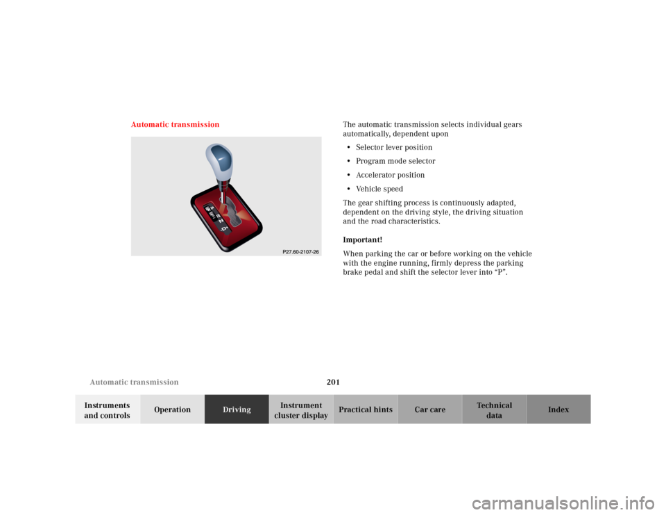
cluster displayPractical hints Car care Index Automatic transmissionThe automatic transmission selects individual gears
automatically, dependent upon
•Selector lever position
•Program mode selector
•Accelerator position
•Vehicle speed
The gear shifting process is continuously adapted,
dependent on the driving style, the driving situation
and the road characteristics.
Important!
When parking the car or before working on the vehicle
with the engine running, firmly depress the parking
brake pedal and shift the selector lever into “P”.
Page 206 of 345
203 Automatic transmission
Te ch n ica l
data Instruments
and controlsOperationDrivingInstrument
cluster displayPractical hints Car care Index Stopping
For brief stops, e.g. at traffic lights, leave the
transmission in gear and hold vehicle with the service
brake.
For longer stops with the engine idling, shift into “N”
or “P” and hold the vehicle with the service brake.
When stopping the vehicle on an uphill gradient, do not
hold it with the accelerator, use the brake. This avoids
unnecessary transmission heat build up.
Maneuvering
To maneuver in tight areas, e.g. when pulling into a
parking space, control the vehicle speed by gradually
releasing the brakes. Accelerate gently and never
abruptly step on the accelerator.
To rock a vehicle out of soft ground (mud or snow),
alternately shift from forward to reverse, while applying
slight partial throttle.
Rocking a vehicle free in this manner may cause the
ABS or traction system malfunction indicator lamp to
come on. Turn off and restart the engine to clear the
malfunction indication.
Wa r n i n g !
Getting out of your vehicle with the selector lever
not fully engaged in position “P” is dangerous.
Also, when parked on an incline, position “P” alone
may not prevent your vehicle from moving,
possibly hitting people or objects.Always set the parking brake in addition to shifting
to position “P”, see page 210 for parking brake. When parked on an incline, also turn front wheel
against curb.Wa r n i n g !
When leaving the vehicle always remove the key
from the steering lock, and lock the vehicle. Do not
leave children unattended in the vehicle, or with
access to an unlocked vehicle. Children could move
the gear selector lever from position “P”, which
could result in an accident or serious injury.
Page 207 of 345
204 Automatic transmission
Te ch n ica l
data Instruments
and controlsOperationDrivingInstrument
cluster displayPractical hints Car care Index
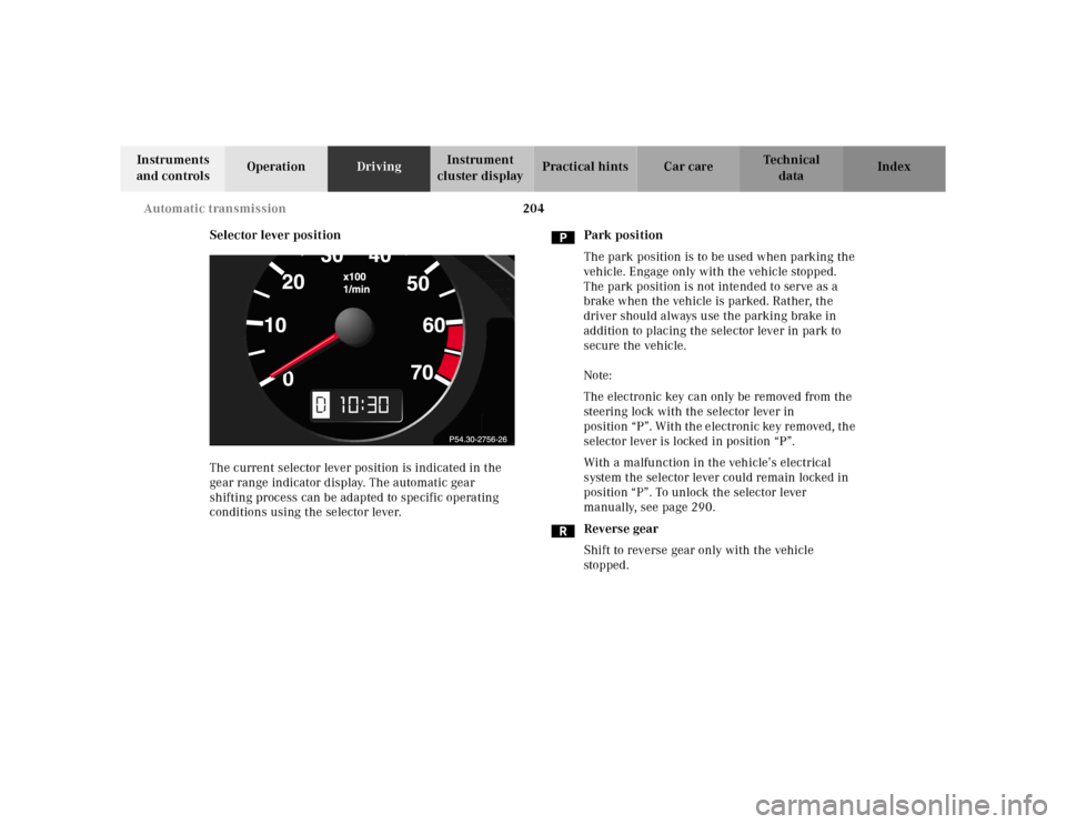
Selector lever position
The current selector lever position is indicated in the
gear range indicator display. The automatic gear
shifting process can be adapted to specific operating
conditions using the selector lever.Park position
The park position is to be used when parking the
vehicle. Engage only with the vehicle stopped.
The park position is not intended to serve as a
brake when the vehicle is parked. Rather, the
driver should always use the parking brake in
addition to placing the selector lever in park to
secure the vehicle.
Note:
The electronic key can only be removed from the
steering lock with the selector lever in
position “P”. With the electronic key removed, the
selector lever is locked in position “P”.
With a malfunction in the vehicle’s electrical
system the selector lever could remain locked in
position “P”. To unlock the selector lever
manually, see page 290.
Reverse gear
Shift to reverse gear only with the vehicle
sto p ped .
10