tow MERCEDES-BENZ E-SEDAN 2014 Manual Online
[x] Cancel search | Manufacturer: MERCEDES-BENZ, Model Year: 2014, Model line: E-SEDAN, Model: MERCEDES-BENZ E-SEDAN 2014Pages: 430, PDF Size: 5.8 MB
Page 368 of 430
Removing the towing eye
X
Unscrew and remove the towing eye.
X Attach cover :to the bumper and press
until it engages.
X Place the towing eye in the vehicle tool kit. Towing the vehicle with the rear axle
raised
! The ignition must be switched off if you
are towing the vehicle with the rear axle
raised. Intervention by ESP ®
could
otherwise damage the brake system.
Only possible for vehicles without
4MATIC.
X Switch on the hazard warning lamps
(Y page 132).
X Turn the SmartKey to position 0in the
ignition lock and remove the SmartKey
from the ignition lock.
X When leaving the vehicle, take the
SmartKey or the KEYLESS-GO key with you.
When towing your vehicle with the rear axle
raised, it is important that you observe the
safety instructions (Y page 364).Towing a vehicle with both axles on
the ground
It is important that you observe the safety
instructions when towing away your vehicle
(Y page 364). The automatic transmission automatically
shifts to position
Pwhen you open the driver's
or front-passenger door or when you remove
the SmartKey from the ignition lock. In order
to ensure that the automatic transmission
stays in position Nwhen towing the vehicle,
you must observe the following points:
X Make sure that the vehicle is stationary and
the SmartKey in the ignition lock is in
position 0.
X Turn the SmartKey to position 2in the
ignition lock.
On vehicles with KEYLESS-GO, use the
SmartKey instead of the Start/Stop button
(Y page 159).
X Depress and hold the brake pedal.
X Shift the automatic transmission to
position N.
X Release the brake pedal.
X Release the parking brake.
X Switch on the hazard warning lamps
(Y page 132).
X Leave the SmartKey in position 2in the
ignition lock.
i When towing with the hazard warning
lamps switched on, use the combination
switch as usual to signal a change of
direction. In this case, only the turn signals
for the desired direction flash. After
resetting the combination switch, the
hazard warning lamps start flashing again. Transporting the vehicle
! You may only secure the vehicle by the
wheels, not by parts of the vehicle such as
axle or steering components. Otherwise,
the vehicle could be damaged.
The towing eye can be used to pull the vehicle
onto a trailer or transporter for transporting
purposes. 366
Towing and tow-startingBreakdown assistance
ProCarManuals.com
Page 369 of 430
X
Turn the SmartKey to position 2in the
ignition lock.
X Shift the automatic transmission to
position N.
As soon as the vehicle has been loaded:
X Prevent the vehicle from rolling away by
applying the parking brake.
X Shift the automatic transmission to
position P.
X Turn the SmartKey to position 0in the
ignition lock and remove the SmartKey
from the ignition lock.
X Secure the vehicle. Notes on 4MATIC vehicles
! Vehicles with 4MATIC must not be towed
with either the front or the rear axle raised,
as doing so will damage the transmission.
If the vehicle has transmission damage or
damage to the front or rear axle, have it
transported on a transporter or trailer.
In the event of damage to the electrical
system
If the battery is defective, the automatic
transmission will be locked in position P. To
shift the automatic transmission to position
N, you must provide power to the vehicle's
electrical system in the same way as when
jump-starting (Y page 362).
Have the vehicle transported on a transporter
or trailer. Tow-starting (emergency engine
starting)
! Vehicles with automatic transmission
must not be started by tow-starting. This
could otherwise damage the transmission.
You can find information on "Jump-starting"
under (Y page 362). Fuses
Important safety notes
G
WARNING
If you manipulate or bridge a faulty fuse or if
you replace it with a fuse with a higher
amperage, the electric cables could be
overloaded. This could result in a fire. There
is a risk of an accident and injury.
Always replace faulty fuses with the specified
new fuses having the correct amperage.
! Only use fuses that have been approved
for Mercedes-Benz vehicles and which
have the correct fuse rating for the system
concerned. Otherwise, components or
systems could be damaged.
The fuses in your vehicle serve to close down
faulty circuits. If a fuse blows, all the
components on the circuit and their functions
stop operating.
Blown fuses must be replaced with fuses of
the same rating, which you can recognize by
the color and value. The fuse ratings are listed
in the fuse allocation chart.
If a newly inserted fuse also blows, have the
cause traced and rectified at a qualified
specialist workshop, e.g. an authorized
Mercedes-Benz Center. Before changing a fuse
Observe the important safety notes
(Y page 367)
X Secure the vehicle against rolling away
(Y page 182).
X Switch off all electrical consumers.
X Turn the SmartKey to position 0in the
ignition lock and remove it (Y page 159).
or
X On vehicles with KEYLESS-GO, make sure
the ignition is switched off (Y page 159).
All indicator lamps in the instrument cluster
must be off. Fuses
367Breakdown assistance Z
ProCarManuals.com
Page 370 of 430
The fuses are located in various fuse boxes:
R Fuse box in the engine compartment on the
left-hand side of the vehicle, when viewed
in the direction of travel
R Fuse box in the trunk/cargo compartment
on the right-hand side of the vehicle, when
viewed in the direction of travel
The fuse allocation chart is located in the
vehicle tool kit in the stowage compartment
under the trunk/cargo compartment floor
(Y page 352). Fuse box in the engine compartment
Observe the important safety notes
(Y page 367) G
WARNING
When the hood is open and the windshield
wipers are set in motion, you can be injured
by the wiper linkage. There is a risk of injury.
Always switch off the windshield wipers and
the ignition before opening the hood.
! Make sure that no moisture can enter the
fuse box when the cover is open.
! When closing the cover, make sure that it
is lying correctly on the fuse box. Moisture
seeping in or dirt could otherwise impair
the operation of the fuses.
X Make sure that the windshield wipers are
turned off.
X Open the hood. X
Use a dry cloth to remove any moisture
from the fuse box.
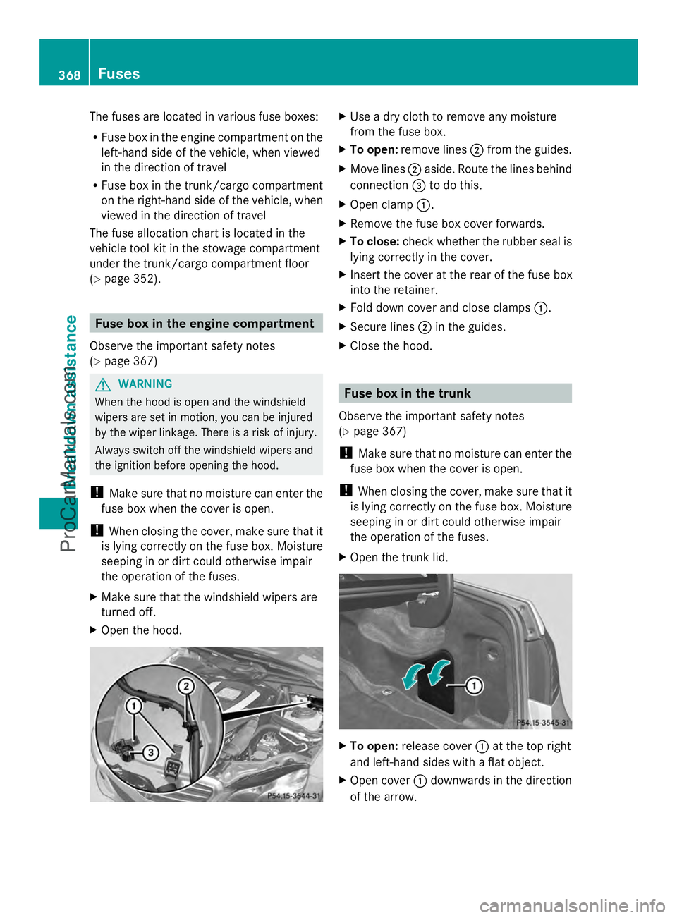
X To open: remove lines ;from the guides.
X Move lines ;aside. Route the lines behind
connection =to do this.
X Open clamp :.
X Remove the fuse box cover forwards.
X To close: check whether the rubber seal is
lying correctly in the cover.
X Insert the cover at the rear of the fuse box
into the retainer.
X Fold down cover and close clamps :.
X Secure lines ;in the guides.
X Close the hood. Fuse box in the trunk
Observe the important safety notes
(Y page 367)
! Make sure that no moisture can enter the
fuse box when the cover is open.
! When closing the cover, make sure that it
is lying correctly on the fuse box. Moisture
seeping in or dirt could otherwise impair
the operation of the fuses.
X Open the trunk lid. X
To open: release cover :at the top right
and left-hand sides with a flat object.
X Open cover :downwards in the direction
of the arrow. 368
FusesBreakdown assistance
ProCarManuals.com
Page 402 of 430
X
Clean the wheel and wheel hub contact
surfaces.
X Slide the wheel to be mounted onto the
alignment bolt and push it on.
X Tighten the wheel bolts until they are
finger-tight.
X Unscrew the alignment bolt.
X Tighten the last wheel bolt until it is finger-
tight.
X Vehicles with a collapsible spare
wheel: inflate the collapsible spare wheel
(Y page 412).
Only then lower the vehicle.
Lowering the vehicle G
WARNING
The wheels could work loose if the wheel nuts
and bolts are not tightened to the specified
tightening torque. There is a risk of accident.
Have the tightening torque immediately
checked at a qualified specialist workshop
after a wheel is changed.
! Vehicles with a collapsible spare
wheel: before lowering the vehicle, inflate
the collapsible spare wheel with the tire
inflation compressor. The wheel rim could
otherwise be damaged. Tightening the wheel nuts (example: vehicle with
an emergency spare wheel)
X
Turn the crank of the jack counter-
clockwise until the vehicle is once again
standing firmly on the ground.
X Place the jack to one side. X
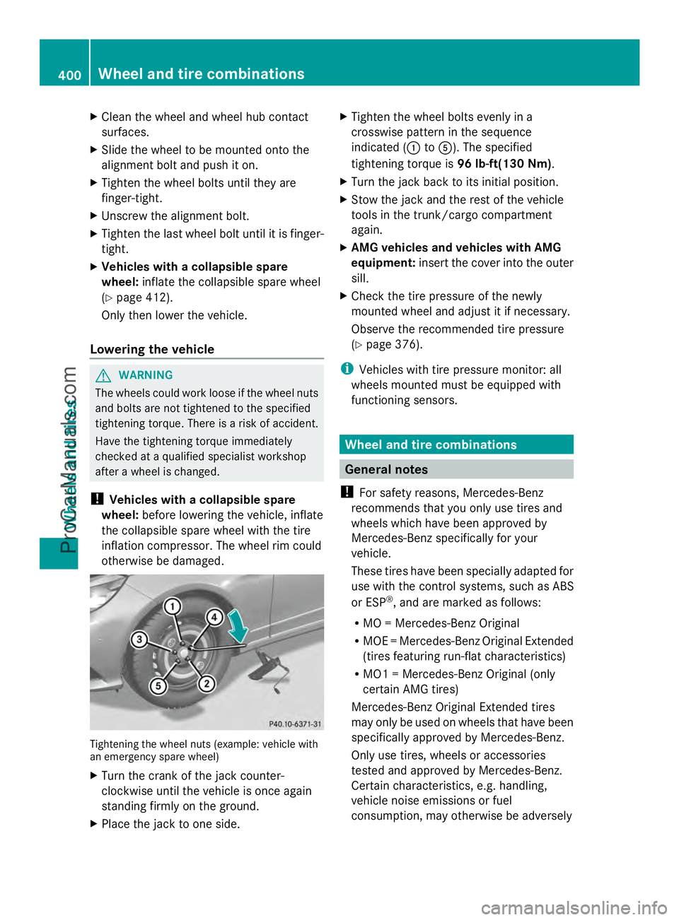
Tighten the wheel bolts evenly in a
crosswise pattern in the sequence
indicated (: toA). The specified
tightening torque is 96 lb-ft(130 Nm).
X Turn the jack back to its initial position.
X Stow the jack and the rest of the vehicle
tools in the trunk/cargo compartment
again.
X AMG vehicles and vehicles with AMG
equipment: insert the cover into the outer
sill.
X Check the tire pressure of the newly
mounted wheel and adjust it if necessary.
Observe the recommended tire pressure
(Y page 376).
i Vehicles with tire pressure monitor: all
wheels mounted must be equipped with
functioning sensors. Wheel and tire combinations
General notes
! For safety reasons, Mercedes-Benz
recommends that you only use tires and
wheels which have been approved by
Mercedes-Benz specifically for your
vehicle.
These tires have been specially adapted for
use with the control systems, such as ABS
or ESP ®
, and are marked as follows:
R MO = Mercedes-Benz Original
R MOE = Mercedes-Benz Original Extended
(tires featuring run-flat characteristics)
R MO1 = Mercedes-Benz Original (only
certain AMG tires)
Mercedes-Benz Original Extended tires
may only be used on wheels that have been
specifically approved by Mercedes-Benz.
Only use tires, wheels or accessories
tested and approved by Mercedes-Benz.
Certain characteristics, e.g. handling,
vehicle noise emissions or fuel
consumption, may otherwise be adversely 400
Wheel and tire combinationsWheels and ti
res
ProCarManuals.com
Page 413 of 430
monitor cannot function reliably. Only
restart the tire pressure loss warning
system/the tire pressure monitor when the
damaged wheel has been replaced with a
new wheel.
Vehicles with tire pressure monitor:
after mounting an emergency spare wheel,
the system may still display the tire
pressure of the removed wheel for a few
minutes. The value displayed for the
mounted emergency spare wheel is not the
same as the current tire pressure of the
emergency spare wheel. "Minispare" emergency spare wheel/
collapsible spare wheel
Opening the stowage well Sedan:
the emergency spare wheel can be
found in the stowage well under the trunk
floor.
X Lift the trunk floor upwards (Y page 312).
Wagon: the emergency spare wheel is
located in the stowage well under the cargo
compartment floor.
X Remove the seat cushions of the folding
bench seat (Y page 114).
X Lift the cargo compartment floor up.
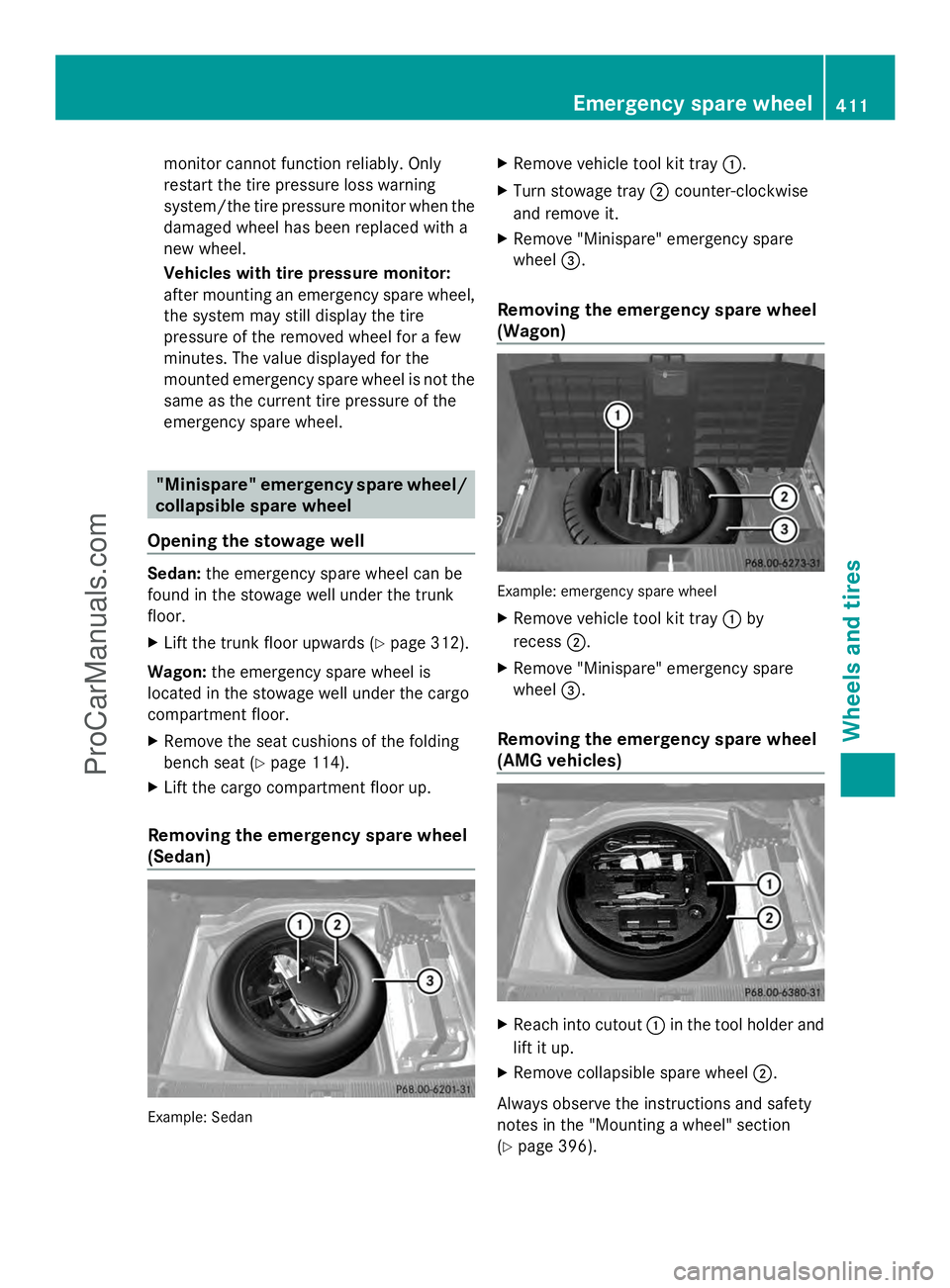
Removing the emergency spare wheel
(Sedan) Example: Sedan X
Remove vehicle tool kit tray :.
X Turn stowage tray ;counter-clockwise
and remove it.
X Remove "Minispare" emergency spare
wheel =.
Removing the emergency spare wheel
(Wagon) Example: emergency spare wheel
X
Remove vehicle tool kit tray :by
recess ;.
X Remove "Minispare" emergency spare
wheel =.
Removing the emergency spare wheel
(AMG vehicles) X
Reach into cutout :in the tool holder and
lift it up.
X Remove collapsible spare wheel ;.
Always observe the instructions and safety
notes in the "Mounting a wheel" section
(Y page 396). Emergency spare wheel
411Wheels and tires Z
ProCarManuals.com
Page 414 of 430
Stowing a used collapsible spare
wheel
! Only place the collapsible spare wheel in
the vehicle when it is dry. Otherwise,
moisture may get into the vehicle.
Take the following steps to stow a used
collapsible spare wheel. It will not otherwise
install into the spare wheel well. Mercedes-
Benz recommends that you have this work
performed at a qualified specialist workshop,
e.g. at an authorized Mercedes-Benz Center.
X Unscrew the valve cap from the valve.
X Use the back of the valve cap to unscrew
the valve insert from the valve and release
the air.
i Fully deflating the tires can take a few
minutes.
X Screw the valve insert back into the valve.
X Screw the valve cap back on.
X Remove the protective sheet from the
vehicle tool kit and pull it over the
collapsible spare wheel.
X Stow the collapsible spare wheel in the
emergency spare wheel well under the
trunk. Inflating the collapsible spare wheel
! Inflate the collapsible spare wheel using
the tire inflation compressor before
lowering the vehicle. The wheel rim could
otherwise be damaged.
! Do not operate the tire inflation
compressor for longer than eight minutes
at a time without a break. It may otherwise
overheat.
The tire inflation compressor can be
operated again once it has cooled down. X
Mount the collapsible spare wheel as
described (Y page 395).
The collapsible spare wheel must be
mounted before it is inflated.
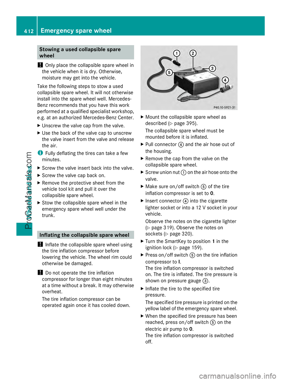
X Pull connector ?and the air hose out of
the housing.
X Remove the cap from the valve on the
collapsible spare wheel.
X Screw union nut :on the air hose onto the
valve.
X Make sure on/off switch Aof the tire
inflation compressor is set to 0.
X Insert connector ?into the cigarette
lighter socket or into a 12 V socket in your
vehicle.
Observe the notes on the cigarette lighter
(Y page 319). Observe the notes on
sockets (Y page 320).
X Turn the SmartKey to position 1in the
ignition lock (Y page 159).
X Press on/off switch Aon the tire inflation
compressor to I.
The tire inflation compressor is switched
on. The tire is inflated. The tire pressure is
shown on pressure gauge =.
X Inflate the tire to the specified tire
pressure.
The specified tire pressure is printed on the
yellow label of the emergency spare wheel.
X When the specified tire pressure has been
reached, press on/off switch Aon the
electric air pump to 0.
The tire inflation compressor is switched
off. 412
Emergency spare wheelWheels and tires
ProCarManuals.com
Page 415 of 430
X
Turn the SmartKey to position 0in the
ignition lock.
X If the tire pressure is higher than the
specified pressure, press pressure release
button ;until the correct tire pressure has
been reached.
X Unscrew union nut :on the air hose from
the valve.
X Screw the valve cap onto the collapsible
spare wheel valve again.
X Stow plug ?and the air hose in the lower
section of the blower housing.
X Stow the tire inflation compressor in the
vehicle. Emergency spare wheel
413Wheels and tires Z
ProCarManuals.com
Page 418 of 430
Useful information
i This Operator's Manual describes all
models and all standard and optional
equipment of your vehicle available at the
time of publication of the Operator's
Manual. Country-specific differences are
possible. Please note that your vehicle may
not be equipped with all features
described. This also applies to safety-
related systems and functions.
i Read the information on qualified
specialist workshops: (Y page 26).Information regarding technical data
General information
G
WARNING
HYBRID vehicles: It is imperative that you read
the HYBRID Supplemental Operating
Instructions included in your vehicle literature
portfolio. You may otherwise not receive all
necessary safety information and warning for
the operation of your vehicle.
i The data stated here specifically refers to
a vehicle with standard equipment. Consult
an authorized Mercedes-Benz Center for
the data for all vehicle variants and trim
levels. Information in the printed Operator's
Manual
In the printed Operator's Manual you can find
information about:
R Vehicle data
R Trunk lid/tailgate opening dimensions
R Tank capacity
R Coolant (engine)
R Engine oil approval and capacity
R DEF filling capacity
R Refrigerant filling capacity and PAG oil
R Towing a trailer Warranty
Your vehicle is covered under the terms of the
warranties printed in the Service and
Warranty Information booklet.
Your authorized Mercedes-Benz Center will
replace and repair all factory-installed parts
in accordance with the following warranty
terms and conditions:
R New Vehicle Limited Warranty
R Emission Systems Warranty
R Emission Performance Warranty
R California, Connecticut, Maine,
Massachusetts, New York, Pennsylvania,
Rhode Island and Vermont Emission
Control System Warranty
R State warranty enforcement laws (Lemon
Laws)
Replacement parts and accessories are
covered by the Mercedes-Benz Parts and
Accessories warranties. These are available
at any authorized Mercedes-Benz Center.
i If you lose the Service and Warranty
Information booklet, contact an authorized
Mercedes-Benz Center to arrange a
replacement. It will be mailed to you. Identification plates
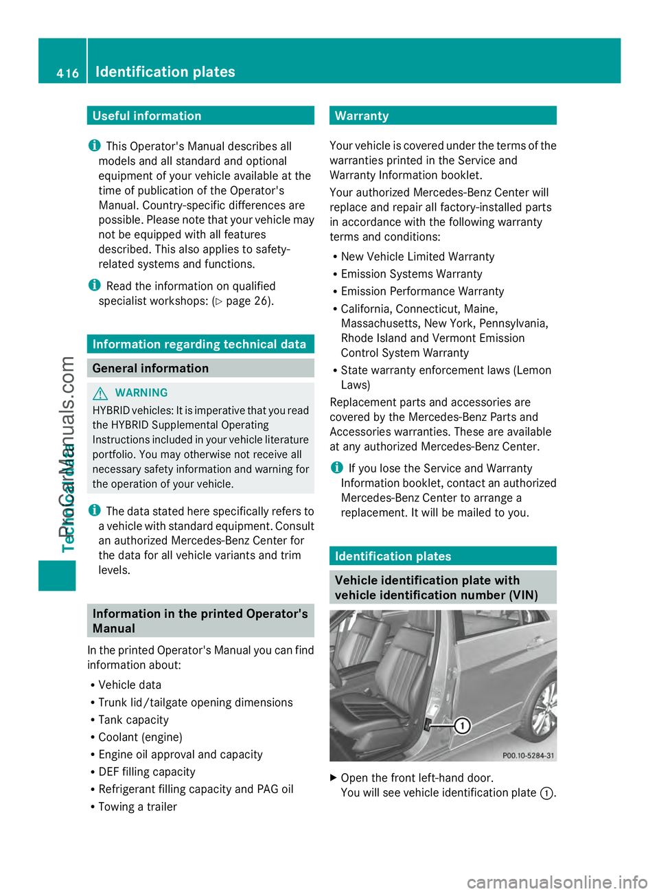
Vehicle identification plate with
vehicle identification number (VIN)
X
Open the front left-hand door.
You will see vehicle identification plate :.416
Identification platesTechnical data
ProCarManuals.com