battery MERCEDES-BENZ E320 WAGON 2003 S210 Owner's Manual
[x] Cancel search | Manufacturer: MERCEDES-BENZ, Model Year: 2003, Model line: E320 WAGON, Model: MERCEDES-BENZ E320 WAGON 2003 S210Pages: 354, PDF Size: 13.99 MB
Page 6 of 354
3 Contents
DrivingControl and operation of radio
transmitters ............................... 186
The first 1 000 miles
(1 500 km) ................................. 187
Maintenance ................................... 187
Tele Aid ........................................... 188
Catalytic converter ........................ 198
Emission control ............................ 199
Steering lock ...................................200
Starting and turning off
the engine ..................................202
Automatic transmission ...............203
Parking brake ................................. 212
Driving instructions ...................... 213
Drive sensibly - Save Fuel ......... 213
Drinking and Driving ................ 213
Pedals ........................................... 213
Power assistance ........................ 214
Brakes .......................................... 214
Driving off ................................... 215
Parking ........................................ 216
Tires ............................................. 216Snow chains ................................ 219
Winter driving instructions ...... 219
Block heater ................................ 221
Standing water ........................... 221
Passenger compartment ........... 221
Traveling abroad ........................ 221
Cruise control ................................ 222
Brake assist system (BAS) ............ 225
Antilock brake system (ABS) ....... 227
Four wheel electronic traction
system (4MATIC) ...................... 229
Electronic stability
program (ESP) ........................... 230
Parking assist (Parktronic) .......... 234
What you should know at the gas
station ......................................... 239
Check regularly and before
a long trip .................................. 241
Instrument cluster displayMalfunction and indicator lamps in
the instrument cluster ............. 244
On-board diagnostic system ..... 244Check engine malfunction
indicator lamp .............................244
Brake warning lamp ..................245
Supplemental restraint system
(SRS) indicator lamp ..................246
Fuel reserve and fuel cap
placement warning ....................246
Electronic stability program (ESP)
— warning lamp ..........................247
BAS / ESP malfunction indicator
lamp ..............................................247
ABS malfunction indicator
lamp ..............................................248
Seat belt warning lamp .............248
Malfunction and indicator lamp in
the center console .....................249
AIRBAG OFF indicator lamp .....249
Malfunction and warning messages
in the multifunction display ...250
DISPLAY DEFECTIVE ................ 251
BATTERY / ALTERNATOR .........252
ABS-SYSTEM ...............................253
BRAKE ASSIST ...........................253
BRAKE LINING WEAR ..............254
Page 7 of 354
4 Contents
BRAKE FLUID .............................254
PARKING BRAKE .......................255
ENGINE FAN ...............................255
COOLANT (coolant level) ..........256
COOLANT TEMP. ........................257
LIGHTING SYSTEM ....................258
LIGHT SENSOR ...........................259
REMOVE KEY .............................259
STEERING GEAR OIL .................260
ENGINE OIL LEVEL ................... 261
WASHER FLUID ..........................262
ELEC. STABIL. PROG. (Electronic
stability program) ......................263
TELE AID .....................................263
Practical hintsFirst aid kit .....................................266
Fuses ................................................267
Electrical outlet ..............................269
Hood .................................................270
Checking engine oil level .............273
Automatic transmission fluid
level ............................................. 274Coolant level ....................................274
Adding coolant ........................... 275
Windshield and headlamp washer
system .........................................276
Windshield and headlamp washer
fluid mixing ratio .......................276
Spare wheel, vehicle tools, storage
compartment ............................. 277
Vehicle jack .................................... 278
Wheels ............................................ 279
Tire replacement ....................... 279
Rotating wheels ......................... 280
Spare wheel .................................... 281
Spare wheel bolts ...................... 281
Changing wheels ........................... 282
Tire inflation pressure ................. 287
Battery ............................................. 289
Jump starting ................................. 291
Towing the vehicle ........................ 294
Transmission selector lever,
manually unlocking ................. 296
Exterior lamps ............................... 297
Headlamp assembly .................. 298
Taillamp assemblies .................. 301Changing batteries in the
electronic key ............................304
Synchronizing remote control .306
Emergency engine shut-down .....306
Emergency operation of sliding /
pop-up roof .................................307
Manual release for fuel
filler flap ....................................308
Replacing wiper blade insert .......308
Roof rack ..........................................311
Vehicle careCleaning and care of the vehicle . 314
Power washer .............................. 315
Tar stains ..................................... 315
Paintwork, painted body
components ................................. 315
Engine cleaning .......................... 316
Vehicle washing ......................... 316
Ornamental moldings ................ 316
Headlamps, taillamps, turn signal
lenses ........................................... 316
Cleaning the parktronic system
sensors ......................................... 317
Page 29 of 354

26 Central locking system
Te ch n i c a l
data Instruments
and controlsOperationDrivingInstrument
cluster displayPractical hints Car care Index
Start lock-out
Important!
Removing the electronic key from the steering lock
activates the start lock-out. The engine cannot be
started.
Inserting the electronic key in the steering lock
deactivates the start lock-out.
Note:
In case the engine cannot be started (vehicle’s battery is
in order), the system is not operational. Contact an
authorized Mercedes-Benz Center or call 1-800-FOR-
MERCedes (in the USA), or 1-800-387-0100 (in Canada).General notes on the central locking system
If the electronic key is inserted in the steering lock, the
vehicle cannot be locked or unlocked with the remote
control.
If the vehicle cannot be locked or unlocked:
•Aim transmitter eye at a receiver of either front door
handle. Check the batteries of the electronic key, see
page 304, or synchronize the remote control, see
page 306.
•Use the mechanical key to unlock the vehicle. To
start engine, insert the electronic key in the steering
lock. There could be a slight delay until the
electronic key can be turned in the steering lock.
Important!
When unlocking the driver’s door with the mechanical
key, the exterior lamps will flash and the alarm will
sound.
To cancel the alarm, insert the electronic key in the
steering lock or press buttonŒ or‹ on the
electronic key.
Page 30 of 354
27 Central locking system
Te ch n i c a l
data Instruments
and controlsOperationDrivingInstrument
cluster displayPractical hints Car care Index Central locking system
Radio frequency and infrared remote control
The electronic key has an integrated radio frequency
and infrared remote control.
Due to the extended operational range of the remote
control, it could be possible to unintentionally lock or
unlock the vehicle by pressing the transmit button. If
one of the transmit buttons is pressed, the battery check
lamp lights up briefly – indicating that the batteries are
in order. See page 304 for checking batteries.
The vehicle doors, tailgate and fuel filler flap can be
centrally locked and unlocked via remote control.
Opening and closing the windows and sliding / pop-up
roof remotely can only be done with the infrared portion
of the remote control. Aim transmitter eye at a
receiver (6 or 7), press and hold transmit button Œ
or ‹.
If the electronic key is inserted in steering lock, the
vehicle cannot be locked or unlocked with the remote
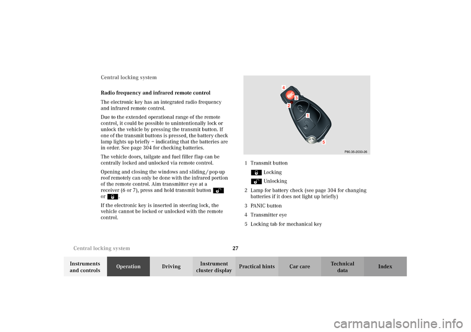
control.1Transmit button
‹ Locking
ΠUnlocking
2Lamp for battery check (see page 304 for changing
batteries if it does not light up briefly)
3PA N I C b u t t o n
4Transmitter eye
5Locking tab for mechanical key
P80.35-2033-26
2
1
4
3
5
Page 32 of 354

29 Central locking system
Te ch n i c a l
data Instruments
and controlsOperationDrivingInstrument
cluster displayPractical hints Car care Index Locking and unlocking with remote control
Unlocking:
Press transmit button Œ. All turn signal lamps blink
once to indicate that the vehicle is unlocked.
The remote control can be programmed for two kinds of
unlocking modes (see below):
Selective unlocking mode –
Press transmit button Œ o nce to un lock dr iver’s d oor
and fuel filler flap.
Press transmit button Πtwice to unlock all doors,
fuel filler flap, and tailgate.
Global unlocking mode –
Press transmit button Πonce to unlock all doors,
fuel filler flap, and tailgate.
Notes:
If the tailgate was previously locked separately, it will
remain locked, seepage36.
The presently active unlocking mode (selective or
global) can only be determined by unlocking the vehicle
with the remote control (see below for changing mode).If within 40 seconds of unlocking with the remote
control, neither door nor tailgate is opened, the
electronic key is not inserted in the steering lock, or the
central locking switch is not activated, the vehicle will
automatically lock.
Locking:
Press transmit button ‹ once. All turn signal lamps
blink three times to indicate that the vehicle is locked.
If they do not blink three times, a door or tailgate is not
properly closed.
Note:
If the vehicle cannot be locked or unlocked by pressing
the transmit button, then it may be necessary to change
the batteries in the electronic key (if ok, battery check
lamp in electronic key will light briefly when pressing
transmit button) or to synchronize the remote control,
see pages 304 and 306.
Page 33 of 354

30 Central locking system
Te ch n i c a l
data Instruments
and controlsOperationDrivingInstrument
cluster displayPractical hints Car care Index
Choosing global or selective mode on remote control
Press and hold transmit buttons ‹ and Œ
simultaneously for five seconds to reprogram the
remote control. Battery check lamp will blink two times
indicating the completed mode change.
Opening and closing windows and
sliding / pop-up roof from outside
(summer opening / convenience feature)
Aim transmitter eye of remote control at a door receiver.
Summer opening:
Continue to press transmit button Πafter unlocking
the vehicle.
The windows and sliding / pop-up roof begin to open
after approximately 1 second.
To interrupt opening procedure, release transmit
button.
Convenience feature:
Continue to press transmit button ‹ after locking
the vehicle.The windows and sliding / pop-up roof begin to close
after approximately 1 second.
To interrupt closing procedure, release transmit button.
Ensure that all side windows and the sliding/pop-up
roof are properly closed before leaving the vehicle.
Note:
If the windows and sliding / pop-up roof cannot be
operated automatically by pressing the transmit button
of t he r emo te c ontr ol then it m ay be n ece ssar y to chan ge
the batteries in the electronic key (if ok, battery check
lamp in electronic key will light briefly when
transmitting), or to synchronize the remote control, see
page 304 and 306.
Wa r n i n g !
Never operate the windows or sliding / pop-up roof
if there is the possibility of anyone being harmed
by the opening or closing procedure.In case the procedure causes potential danger, the
procedure can be immediately halted by releasing
the remote control button. To reverse direction of
movement, press Œ for opening or ‹ for
closing.
Page 47 of 354
44 Seats
Te ch n i c a l
data Instruments
and controlsOperationDrivingInstrument
cluster displayPractical hints Car care Index
Synchronizing head restraints
If the power supply was interrupted (battery
disconnected or empty), the head restraints are no
longer adjusted automatically.
To resynchronize the adjustment feature, turn
electronic key in steering lock to position 2, move the
seat completely forward and the head restraint fully
down, and hold respective buttons for approximately
two seconds.Caution!
Do not remove head restraints except when mounting
seat covers. For removal refer to Head Restraints, Front,
see page 48. Whenever restraints have been removed be
sure to reinstall them before driving.
Page 55 of 354
52 Seats
Te ch n i c a l
data Instruments
and controlsOperationDrivingInstrument
cluster displayPractical hints Car care Index
Seat heater
The seat heaters can be switched on with the electronic
key in steering lock positions 1 or 2.Notes:
When in operation, the seat heater consumes a large
amount of electrical power. It is not advisable to use the
seat heater longer than necessary.
The seat heaters may automatically switch off if too
many power consumers are switched on at the same
time, or if the battery charge is low. When this occurs,
the indicator lamp in the switch will blink (both
indicator lamps blink during rapid seat heating mode).
The seat heaters will switch on again automatically as
soon as sufficient voltage is available.
If the blinking of the indicator lamps is distracting to
you, the seat heaters can be switched off.
Page 59 of 354
56 Seats
Te ch n i c a l
data Instruments
and controlsOperationDrivingInstrument
cluster displayPractical hints Car care Index
Notes:
When in operation, the seat ventilation consumes a
large amount of electrical power. It is not advisable to
use the seat ventilation longer than necessary.
The seat ventilation may automatically switch off if too
many power consumers are switched on at the same
time or if the battery charge is low. When this occurs,
one or more indicator lamps in the switch will blink.
The seat ventilation will switch on again automatically
as soon as sufficient voltage is available.
If the blinking indicator lamps pose a distraction, the
seat ventilation can be switched off.
Page 118 of 354
115 Flexible service system
Te ch n i c a l
data Instruments
and controlsOperationDrivingInstrument
cluster displayPractical hints Car care Index The service indicator disappears automatically after
30 seconds or if buttonJon the instrument cluster is
pressed.
Calling up service indicator manually:
Turn the electronic key in steering lock to position
1or2.
Call up the trip odometer and main odometer by
pressing button è or ÿ on the multifunction
steering wheel until the display appears. See page 96.
Press button j or k until the FSS indicator
appears.
Pressing the è or ÿ button displays the next or
previous system.
Important!
The FSS indicator is not an engine oil level indicator.
See page 117 for engine oil level indicator.Note:
When disconnecting vehicle battery for one or more
days at a time, such days will not be counted. Any such
days not counted by the FSS can be added by your
Mercedes-Benz Center.
The interval between services is determined by the type
of driving for which the vehicle is used. For example,
driving at extreme speeds, and cold starts combined
with short distance driving in which the engine does not
reach operating normal temperature, reduce the interval
between services.