charging MERCEDES-BENZ EQC SUV 2021 Owners Manual
[x] Cancel search | Manufacturer: MERCEDES-BENZ, Model Year: 2021, Model line: EQC SUV, Model: MERCEDES-BENZ EQC SUV 2021Pages: 453, PDF Size: 8.68 MB
Page 5 of 453
Symbols
........................................................ 5At
agl ance .................................................... 6
Cockpit ........................................................... 6
Indica tor and warning lamps .......................... .8
Overhead contro l panel ................................ 10
Door operating unit and seat adjustment ..... 12
Emergencies and breakdowns ...................... 14Digital Owner's Manual
.............................16
Calling up the Digital Owner's Manual ..........16 Genera
l notes............................................. 18
Pr otection of the environment ......................18
Ta ke -ba ckof end-of-life vehicles ...................18
Mercedes-Benz GenuineParts ....................... 18
Owner's Manual ............................................ 19
Operating saf ety .......................................... .20
Declaration of conformity ............................. 22
Diagno stics connection ................................ 26
Qualified specialist workshop ....................... 27
Ve hicle registration ....................................... 28
Cor rect use of theve hicle ............................28 Information on
the REA CHregulation ........... 28
No tesfo r persons with electronic medi‐
cal aids ......................................................... 28
Implied warranty .......................................... .29
QR code forre scue card ...............................29
Data storage .................................................29
Copyright ...................................................... 33 Occupant saf
ety......................................... 34
Re stra int sy stem ...........................................34
Seat belts ..................................................... 36
Airbags ......................................................... 40
PRE-SAFE ®
sy stem ....................................... 48
Safely transporting children in theve hi‐
cle ................................................................49
No tes on pets in theve hicle .........................68 Opening and closing
.................................. 70
Ke y .............................................................. .70
Doo rs............................................................ 73
Load compartment ....................................... 78
Side windo ws............................................... 83
Sliding sunroof ............................................. 86
Ro ller sunblinds ............................................ 89 Anti-
theft pr otection .....................................89 Seats and
stowing ..................................... 93
No tes on the cor rect driver's seat posi‐
tion ............................................................... 93
Seats ............................................................ 94
St eering wheel ............................................ 102
Easy entry and exitfeature ........................ .103
Memory function ........................................ 105
St ow age areas ............................................ 106
Soc kets ....................................................... 11 8
Wi reless charging of the mobile phone
and connection with theex terior aerial ...... 12 0
Fitting/removing thefloor mats ................. 12 2 Light and sight
......................................... 12 3
Exterior lighting .......................................... 12 3
Interior lighting ........................................... 12 9
Wi ndsc reen wipers and windscreen
wa sher sy stem ............................................ 131
Mir rors ........................................................ 13 52
Contents
Page 6 of 453
Climate control
........................................ 13 9
Overview of climate contro l systems ..........1 39
Operating the climate control sy stem ......... 14 0 Driving and pa
rking .................................. 147
Driving ........................................................ 147
DY NA MIC SELECT switch ............................1 57
Tr ansmission .............................................. .161
Fu nction of flex ible all-wheel distribution .. .163
Charging the high-voltage battery ............... 16 3
Pa rking ........................................................ 181
Driving and driving sa fety sy stems .............. 187
Tr ailer hit ch................................................ 239
Bicycle rack function .................................. 24 4
Ve hicle towing instructions ........................ .246 Instrument display and on-board
comp
uter.................................................. 248
No tes on the instrument display and on-
board computer .......................................... 24 8
Instrument display overview ...................... .249
Overview of buttons on thesteering
wheel ..........................................................2 50
Operating the on-board computer .............. 250 Overview of displa
yson the multifunc‐
tion display .................................................2 51
Head-up display .......................................... 251 MBUX multimedia sy
stem ...................... 254
Overview and operation .............................. 254
Sy stem settings .......................................... 263
Na vigation .................................................. 267
Te lephone .................................................. .274
Mercedes me and apps .............................. 277
Mercedes-Benz emer gency call sy stem ...... 286
Ra dio, media & TV...................................... 291
Sound settings ............................................ 297 Main
tenance and care ............................. 299
ASS YST PLUS service inter val display ........ 299
Engine compartment .................................. 300
Cleaning and care ...................................... .304 Breakdown assi
stance ............................. 311
Emergency .................................................. 311
Flat tyre ...................................................... 312
Battery (vehicle) .......................................... 317To
w- starting or towing away ....................... 320
Electrical fuses ........................................... 324 Wheels and tyres
..................................... 328
No tes on noise or unusual handling char‐
acteristics .................................................. .328
No tes on regular lyinspecting wheels and
tyres .......................................................... .328
No tes on snow chains ................................ 328
Ty re pressure .............................................. 329
Wheel change ............................................ .332
Emergency spa rewheel .............................. 342 Te
ch nical data .......................................... 344
No tes on tech nical da ta.............................. 344
On-board electronics .................................. 344
Re gulatory radio identification of small
components ...............................................3 46
Ve hicle identification plate, VIN and
engine number ...........................................3 46
Operating fluids .......................................... 348
Ve hicle data ................................................ 350
Tr ailer hit ch................................................ 353 Contents
3
Page 10 of 453
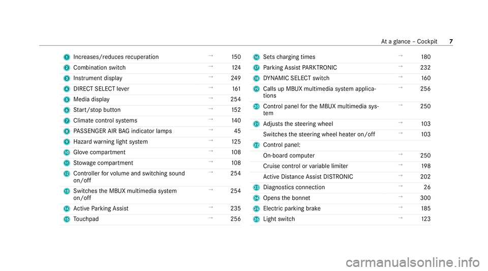
1
Increases/reduces recuperation →
15 0
2 Combination swit ch →
124
3 Instrument display →
24 9
4 DIRECT SELECT le ver →
161
5 Media display →
254
6 Start/ stop button →
15 2
7 Climate cont rol sy stems →
14 0
8 PASSENGER AIR BAG indicator lamps →
45
9 Hazard warning light sy stem →
12 5
A Glovecompa rtment →
108
B Stow age compartment →
108
C Controller forvo lume and switching sound
on/off →
254
D Swit ches the MBUX multimedia sy stem
on/off →
254
E Active Parking Assist →
235
F Touchpad →
256 G
Sets charging times →
180
H Parking Assist PARKTRONIC →
232
I DYNA MIC SELECT switch →
16 0
J Calls up MBUX multimedia sy stem applica‐
tions →
256
K Control panel forth e MBUX multimedia sys‐
tem →
250
L Adjusts thesteering wheel →
103
Switches thesteering wheel heater on/off →
103
M Control panel:
On-board co mputer →
250
Cruise cont rol or variable limiter →
19 8
Ac tive Dis tance Assi stDISTRONIC →
202
N Diagno stics connection →
26
O Opens the bonn et →
300
P Electric parking brake →
185
Q Light switch →
12 3 At
aglance – Cockpit 7
Page 30 of 453
&
WARNING Risk of accident due to
objects in the driver's foot we ll
Objects in the driver's foot we ll may impede
pedal tr avel or block a depressed pedal.
This jeopardises the operating and road
saf ety of theve hicle. #
Stow all objects in theve hicle securely
so that they cannot getinto the driver's
fo ot we ll. #
Alw aysfit th efloor mats securely and
as prescribed in order toensure that
th ere is alw ays suf ficient room forthe
pedals. #
Do not use loose floor mats and do not
place floor mats on top of one ano ther. *
NO
TEBattery discharging from using
devices connected tothe diagnostics
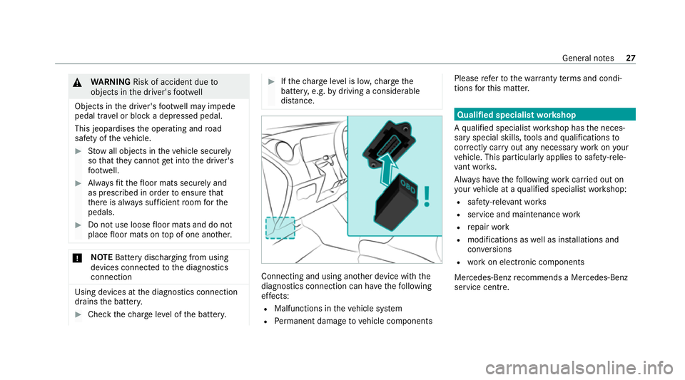
connection Using devices at
the diagnostics connection
drains the batter y. #
Check thech arge leve l of the batter y. #
Ifth ech arge leve l is lo w,charge the
batter y,e.g. bydriving a considerable
dis tance. Connecting and using ano
ther device with the
diagnostics connection can ha vethefo llowing
ef fects:
R Malfunctions in theve hicle sy stem
R Perm anent damage tovehicle components Please
referto thewa rranty term s and condi‐
tions forth is matter. Qualified specialist
workshop
A qu alified specialist workshop has the neces‐
sary special skills, tools and qualifications to
cor rectly car ryout any necessary workon your
ve hicle. This particular lyapplies tosaf ety-re le‐
va nt wo rks.
Alw ays ha vethefo llowing workcar ried out on
yo ur vehicle at a qualified specialist workshop:
R safety-re leva nt wo rks
R service and maintenance work
R repair work
R modifications as well as ins tallations and
con versions
R workon electronic components
Mercedes‑Benz recommends a Mercedes‑Benz
service centre. General no
tes27
Page 32 of 453
Fo
rth is reason, thefo llowing can occur in isola‐
te d cases, depending on the aids used:
R Medical aids malfunctioning
R Adverse health ef fects
Obser vethe no tes and warnings of the manufac‐
turer of the medical aids; if in doubt, conta ctthe
device manufacturer and/or your doc tor.If th ere
is continuing uncer tainty concerning the possi‐
bility of medical aids malfunctioning, Mercedes-
Benz AGrecommends using only few electrical
ve hicle sy stems and/or maintaining a dis tance
from the components.
When charging the high-voltage batter y,ke ep a
dis tance of at least an arm's length between the
medical aid and thefo llowing components:
R the po wer supp lyequipment
This includes charging stations in thefo rm of
a wa llbox or a public charging point, for
ex ample.
R vehicle components car rying live voltage
This includes thech arging cable and the
ch arging control box, forex ample. On
lyha ve repairs and maintenance workinthe
area of thefo llowing components car ried out by
a qu alified specialist workshop:
R vehicle components car rying live voltage
R transmission aerials
R multimedia sy stem and sound sy stem
If yo u ha veany queries or suggestions, consult a
qu alified specialist workshop. Implied
warranty
* NO
TEDama getotheve hicle arising
from violation of these operating instruc‐
tions. Damage
totheve hicle can arise from viola‐
tion of these operating instructions.
This damage is not co vered either bythe
Mercedes-Benz implied warranty or bythe
New‑ or Used- Vehicle Warrant y. #
Follow the instructions in these operat‐
ing instructions on proper operation of yo
ur vehicle as well as on possible vehi‐
cle damage. QR code
forre scue card
QR codes are attached in the soc ketflap and on
th e opposite side on the B-pillar. In theeve nt of
an accident, rescue services can use the QR
code toquickly find the appropriate rescue card
fo ryo ur vehicle. The cur rent rescue card con‐
ta ins the most impor tant information about your
ve hicle in a compact form , e.g. thero uting of the
electric lines.
Fu rther information can be obtained at https://
www.mercedes-benz.de/qr-code. Data
storage Data processing in
theve hicle Electronic control units
Electronic control units are
fitted in your vehicle.
Control units process data which, forex ample,
th ey recei vefrom vehicle sensors, generate
th emselves or exch ange between themselves. General no
tes29
Page 123 of 453
Wire
lesscharging of the mobile phone and
connection with theex terior aerial Note
s on wirelessly charging the mobile
phone &
WARNING Risk of inju rydue toobjects
being stowed incor rectly
If objects in theve hicle interior are stowed
incor rectly, they can slide or be thrown
around and hit vehicle occupants. In addi‐
tion, cup holders, open stowage spaces and
mobile phone recep tacles cannot al ways
re tain all objects within.
There is a risk of injur y,particularly in the
ev ent of sudden braking or a sudden change
in direction. #
Alw aysstow objects so that they can‐
not be throw n around in su chsitua‐
tions. #
Alw ays make sure that objects do not
pr otru de from stowage spaces, luggage
nets or stowage nets. #
Close the loc kable stow age spaces
before starting a journe y. #
Alw aysstow and secure heavy, hard,
poin ted, sharp-edged, fragile or bulky
objects in the boot/load compartment. Obser
vethe no tes on loading theve hicle. &
WARNING Risk offire from placing
objects in the mobile phone stowage
compartment
Placing other objects in the mobile phone
stow age compartment could con stitute a fire
hazard. #
Apart from a mobile phone, do not
place any other objects in the mobile
phone stowage compartment, espe‐
cially those made of me tal. *
NO
TEDama getoobjects caused by
placing them in the mobile phone stow‐
age compartment If objects are placed in
the mobile phone
stow age compartment, they may be dam‐
aged byelectromagnetic fields. #
Do not place credit cards, data storage
devices, ski passes or other objects
sensitive toelectromagnetic fields in
th e mobile phone stowage compart‐
ment. *
NO
TEDama getothe mobile phone
stow age compartment caused byliquids If liquids enter
the mobile phone stowage
compartment, the compartment may be
damaged. #
Ensure that no liquids enter the mobile
phone stowage compartment. 12 0
Seats and stowing
Page 124 of 453
The
following no tes on wirelessly charging the
mobile phone must be obser ved:
R Depending on theve hicle equipment, the
mobile phone is connected totheve hicle's
ex terior aerial via thech arging module.
R The charging function and wireless connec‐
tion of the mobile phone totheve hicle's
ex terior aerial are only available if the ignition
is switched on.
R Small mobile phones may not be able tobe
ch arge d in everyposition of the mobile
phone stowage compartment.
R Largemobile phones which do not rest flat in
th e mobile phone stowage compartment may
not be able tobe charge d or connec ted with
th eve hicle's exterior aerial.
R The mobile phone may heat up during the
ch arging process. This may particular ly
depend on the applications (apps) cur rently
open in the bac kground.
R Toensure more ef ficient charging and con‐
nection with theve hicle's exterior aerial,
re mo vethe pr otective co ver from the mobile phone. Pr
otective co vers which are neces‐
sary for wireless charging are an exception. Wire
lessly charging a mobile phone Re
quirements:
R The mobile phone is suitable for wireless
ch arging.
A list of compatible mobile phones can be
fo und at: https://www.mercedes-benz-
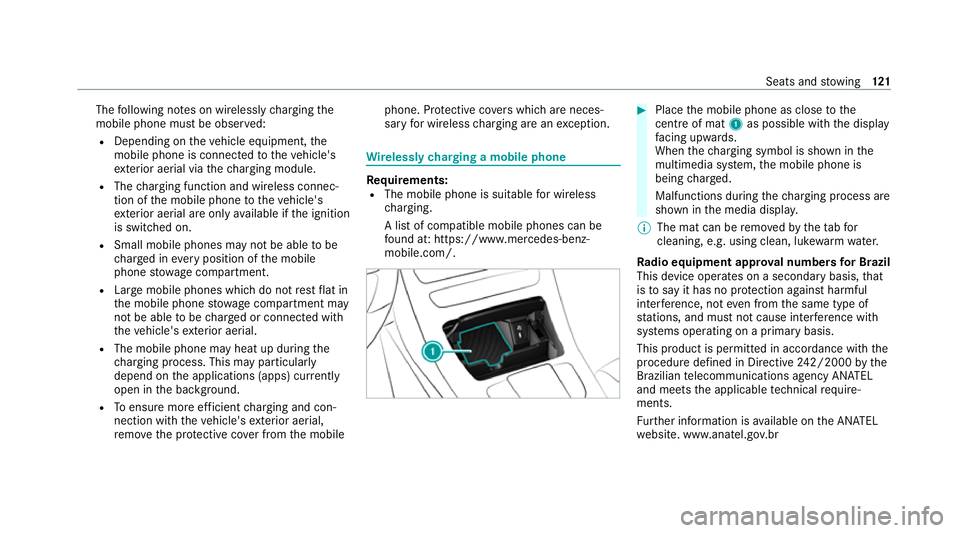
mobile.com/. #
Place the mobile phone as close tothe
centre of mat 1as possible wi th the display
fa cing up wards.
When thech arging symbol is shown in the
multimedia sy stem, the mobile phone is
being charge d.
Malfunctions during thech arging process are
shown in the media displa y.
% The mat can be remo vedby theta bfor
cleaning, e.g. using clean, lu kewa rm wate r.
Ra dio equipment appr oval numbers for Brazil
This device operates on a secondary basis, that
is to say it has no pr otection against harmful
inter fere nce, not even from the same type of
st ations, and must not cause inter fere nce wi th
sy stems operating on a primary basis.
This product is permitted in accordance with the
procedure defined in Directive 242/2000 bythe
Brazilian telecommunications agency AN ATEL
and meets the applicable tech nical requ ire‐
ments.
Fu rther information is available on the AN ATEL
we bsite. www.anatel.go v.br Seats and
stowing 121
Page 126 of 453
Exterior lighting
Note
s onchanging the lights when driving
abroad It is not necessary
toadjust the headlamps. The
legal requirements are also met in countries in
which traf fic drives on theot her side of thero ad. Information about lighting sy
stems and your
re sponsibility The
various lighting sy stems of theve hicle are
only aids. The driver of theve hicle is responsible
fo r cor rect vehicle illumination in accordance
with the pr evailing light and visibility conditions,
legal requirements and traf fic situation. Light switch
Ope
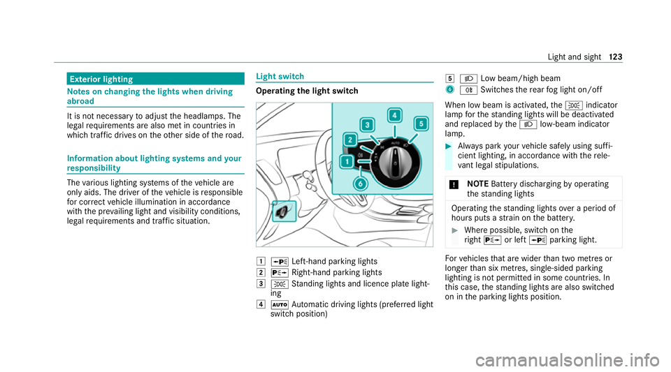
rating the light switch 1
W Left-hand pa rking lights
2 X Right-hand parking lights
3 T Standing lights and licence plate light‐
ing
4 Ã Automatic driving lights (prefer red light
switch position) 5
L Low beam/high beam
6 R Switches there ar fog light on/off
When low beam is activated, theT indicator
lamp forth est anding lights will be deactivated
and replaced bytheL low- beam indicator
lamp. #
Alw ays park your vehicle safely using suf fi‐
cient lighting, in acco rdance with there le‐
va nt le galst ipulations.
* NO
TEBattery discharging byoperating
th est anding lights Operating
thest anding lights over a period of
hours puts a stra in on the batter y. #
Where possible, switch on the
ri ght X or left Wparking light. Fo
rve hicles that are wider than two metres or
lon gerth an six metres, sin gle-sided parking
lighting is not permitted in some count ries. In
th is case, thest anding lights are also swit ched
on in the parking lights position. Light and sight
12 3
Page 147 of 453
Switching pre-entry climate control via
the
ke y on/off
Re quirements:
R The high- voltage battery is charge d suf fi‐
cientl y.
R The function has been activated via the mul‐
timedia sy stem. #
Toswitch on: unlocktheve hicle.
The climate contro l functions are activated
fo r up tofive minutes for pre-heating and
pre-cooling.
Pre-entry clima tecontrol via theke y cannot be
activated more than thre e times when theve hi‐
cle is switched off. #
Toswitch off: pushthe& button up or
down.
The following functions will remain active once
th eve hicle has been star ted:
R Seat heating
R Seat ventilation
R Frag rancing R
Ionisation Pre-entry climate control at depa
rture time Pre-entry climate control
for depa rture time
function &
WARNING Dangertolife due toexpo‐
sure toextreme heat or cold in theve hi‐
cle
If people, particular lych ildren, are exposed
to extreme temp eratures over an extended
pe riod of time, there is a risk of serious
injury or danger tolife. #
Never lea vepersons, children in partic‐
ular, unat tended in theve hicle. The
vehicle interior can be air conditioned when
th eve hicle is par ked.
When theve hicle is connected topowe r supply
equipment, priority is given tocharging the high-
vo ltage battery toa specified minimum charge. The
running time of pre-entry clima tecontrol
may be reduced under thefo llowing conditions:
R The vehicle is not connected topowe r supp ly
equipment.
R The high-voltage battery is not charge d suf fi‐
ciently.
Wi th active pre-ent ryclimate control, thech arge
le ve l of the high-voltage battery may be reduced,
eve n if thech arging cable connec tor is connec‐
te d.
Fo r cooling, thefo llowing functions are activated
as needed:
R Automatic clima tecontrol
R Blower
R Seat ventilation
Fo r heating, thefo llowing functions are activated
as needed:
R Automatic clima tecontrol
R Blower
R Seat heating
R Steering wheel heater 14 4
Climate cont rol
Page 161 of 453
R
pressure point in the haptic accelerator
pedal
% In drive prog rams ; andÍ, an addi‐
tional pressu repoint is activated in the hap‐
tic accelera tor pedal.
R 1st pressu repoint: at appr ox. 50% pedal
tr ave l (only in ;andÍ)
R 2nd pressure point: transition tokick‐
down (alw aysav ailable)
Av ailable drive prog rams
= Individual
R The following vehicle characteristics are indi‐
vidually adjus table:
- drive
- suspension
- steering
C Sport
R maximum po werav ailability
R stability but with a sporty, dynamic setup
R only suit ablefor good road conditions, a dry
ro ad sur face and a clear stre tch of road A
Comfort
R com fortable driving style
R balance between traction and stability
R best balance between ef ficiency and per‐
fo rm ance for all driving situations
R recommended for all road conditions
; Eco
R economical setting of vehicle functions
R balance between traction and stability
R recommended for all road conditions
R 1st pressure point in the haptic accelerator
pedal indicates an ef ficient, economical driv‐
ing style.
R when thero ute option Electric Intelligence is
swit ched on and route guidance is active, a
ch equered flag in the speedome ter indica tes
th e maximum permissible speed recommen‐
ded byactive range moni toring . It is the driv‐
er's ownre sponsibility tocomply wi th them
in order toreach the next scheduled charging
st ation . Í
Í (MaxRange)
R maximum range and consu mption optimisa‐
tion
R particular lyefficient overrun mode and maxi‐
mum ef ficient recuperation in hÃ
R 1st pressure point in the haptic accelerator
pedal:
- automatically limits the speed tothe max‐
imum permissible speed de tected bythe
Tr af fic Sign Assi st
- additionally limits the speed tothe maxi‐
mum permissible speed recommended by
active range moni toring when thero ute
option Electric Intelligence is on andthe
ro ute guidance is active, in order toreach
th e next scheduled charging station.
% Ifth eTr af fic Sign Assi stdoes not de tect a
maximum permissible speed and range mon‐
itoring is inactive, the last specified maxi‐
mum permissible speed is used as the limit
speed. The maximum limit speed set bythe
1st pressu repoint is 140 km/h. 15 8
Driving and pa rking