MERCEDES-BENZ G-Class 2009 W463 Owner's Manual
Manufacturer: MERCEDES-BENZ, Model Year: 2009, Model line: G-Class, Model: MERCEDES-BENZ G-Class 2009 W463Pages: 264, PDF Size: 6.98 MB
Page 241 of 264
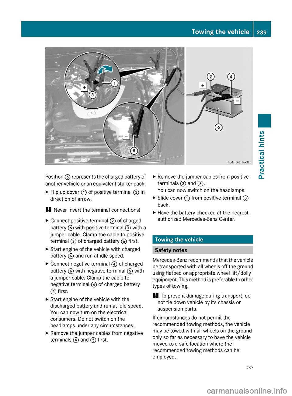
Position B represents the charged battery of
another vehicle or an equivalent starter pack.
XFlip up cover : of positive terminal = in
direction of arrow.
! Never invert the terminal connections!
XConnect positive terminal ; of charged
battery B with positive terminal = with a
jumper cable. Clamp the cable to positive
terminal ; of charged battery B first.
XStart engine of the vehicle with charged
battery B and run at idle speed.
XConnect negative terminal ? of charged
battery B with negative terminal A with
a jumper cable. Clamp the cable to
negative terminal ? of charged battery
B first.
XStart engine of the vehicle with the
discharged battery and run at idle speed.
You can now turn on the electrical
consumers. Do not switch on the
headlamps under any circumstances.
XRemove the jumper cables from negative
terminals ? and A first.
XRemove the jumper cables from positive
terminals ; and =.
You can now switch on the headlamps.
XSlide cover : from positive terminal =
back.
XHave the battery checked at the nearest
authorized Mercedes-Benz Center.
Towing the vehicle
Safety notes
Mercedes-Benz recommends that the vehicle
be transported with all wheels off the ground
using flatbed or appropriate wheel lift/dolly
equipment. This method is preferable to other
types of towing.
! To prevent damage during transport, do
not tie down vehicle by its chassis or
suspension parts.
If circumstances do not permit the
recommended towing methods, the vehicle
may be towed with all wheels on the ground
only so far as necessary to have the vehicle
moved to a safe location where the
recommended towing methods can be
employed.
Towing the vehicle239Practical hints463_AKB; 2; 52, en-USd2ureepe,Version: 2.11.7.12008-12-02T10:52:11+01:00 - Seite 239Z
Page 242 of 264
Page 243 of 264
and activate combination switch for left or
right turn signal in usual manner – only the
selected turn signal will operate. Upon
canceling the turn signal, the hazard
warning flasher will operate again.
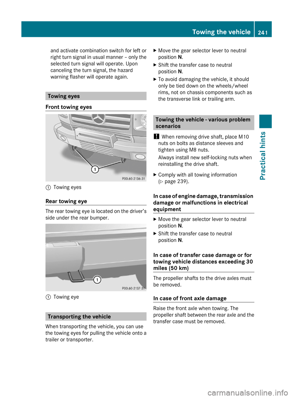
Towing eyes
Front towing eyes
:Towing eyes
Rear towing eye
The rear towing eye is located on the driver’s
side under the rear bumper.
:Towing eye
Transporting the vehicle
When transporting the vehicle, you can use
the towing eyes for pulling the vehicle onto a
trailer or transporter.
XMove the gear selector lever to neutral
position N.
XShift the transfer case to neutral
position N.
XTo avoid damaging the vehicle, it should
only be tied down on the wheels/wheel
rims, not on chassis components such as
the transverse link or trailing arm.
Towing the vehicle - various problem
scenarios
! When removing drive shaft, place M10
nuts on bolts as distance sleeves and
tighten using M8 nuts.
Always install new self-locking nuts when
reinstalling the drive shaft.
XComply with all towing information
(Y page 239).
In case of engine damage, transmission
damage or malfunctions in electrical
equipment
XMove the gear selector lever to neutral
position N.
XShift the transfer case to neutral
position N.
In case of transfer case damage or for
towing vehicle distances exceeding 30
miles (50 km)
The propeller shafts to the drive axles must
be removed.
In case of front axle damage
Raise the front axle when towing. The
propeller shaft between the rear axle and the
transfer case must be removed.
Towing the vehicle241Practical hints463_AKB; 2; 52, en-USd2ureepe,Version: 2.11.7.12008-12-02T10:52:11+01:00 - Seite 241Z
Page 244 of 264
Page 245 of 264
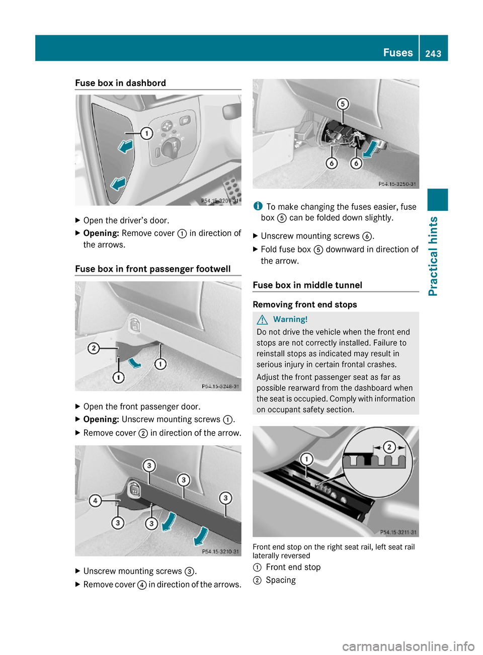
Fuse box in dashbordXOpen the driver’s door.XOpening: Remove cover : in direction of
the arrows.
Fuse box in front passenger footwell
XOpen the front passenger door.XOpening: Unscrew mounting screws :.XRemove cover ; in direction of the arrow.XUnscrew mounting screws =.XRemove cover ? in direction of the arrows.
iTo make changing the fuses easier, fuse
box A can be folded down slightly.
XUnscrew mounting screws B.XFold fuse box A downward in direction of
the arrow.
Fuse box in middle tunnel
Removing front end stops
GWarning!
Do not drive the vehicle when the front end
stops are not correctly installed. Failure to
reinstall stops as indicated may result in
serious injury in certain frontal crashes.
Adjust the front passenger seat as far as
possible rearward from the dashboard when
the seat is occupied. Comply with information
on occupant safety section.
Front end stop on the right seat rail, left seat raillaterally reversed
:Front end stop;SpacingFuses243Practical hints463_AKB; 2; 52, en-USd2ureepe,Version: 2.11.7.12008-12-02T10:52:11+01:00 - Seite 243Z
Page 246 of 264
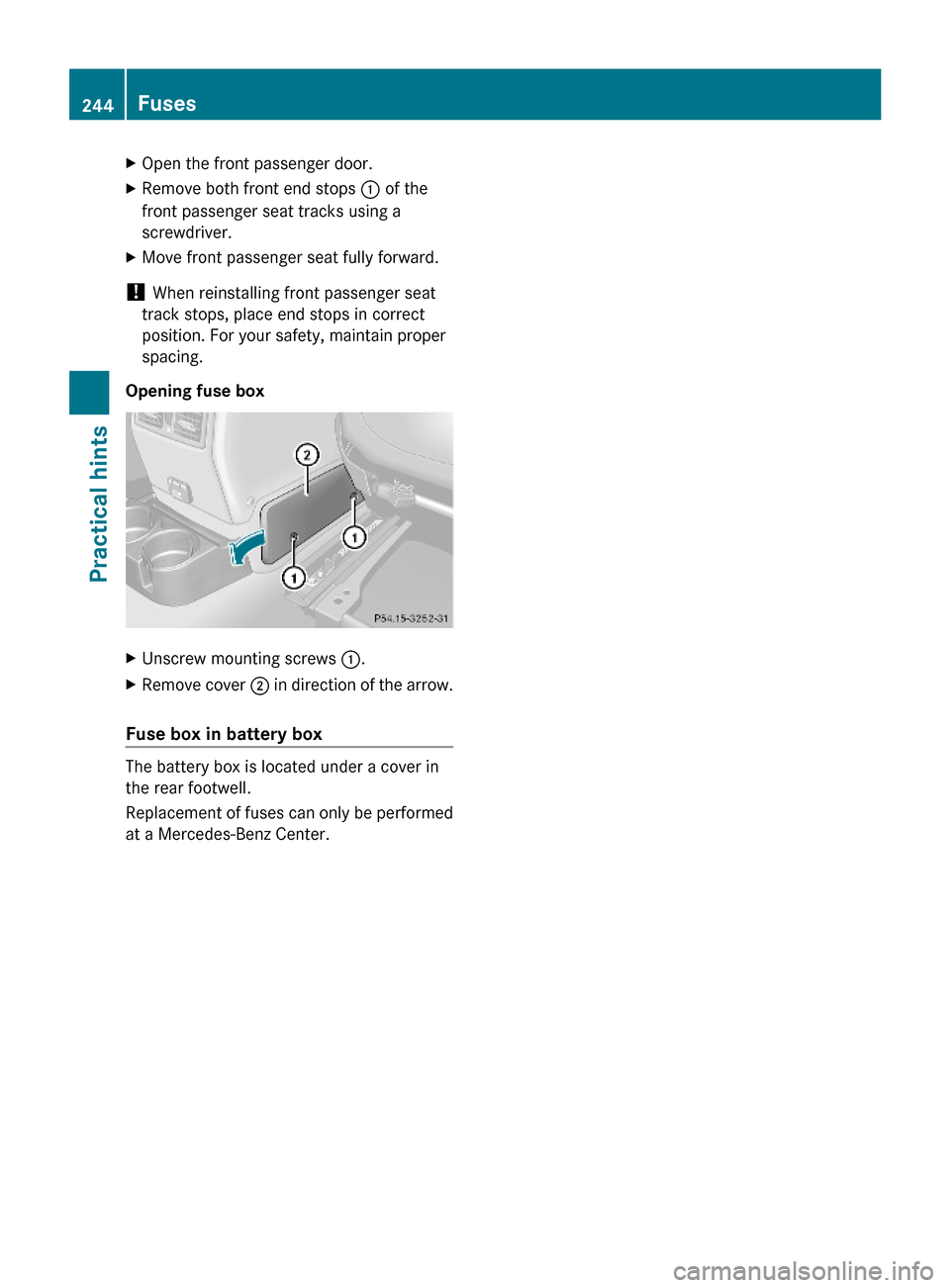
XOpen the front passenger door.XRemove both front end stops : of the
front passenger seat tracks using a
screwdriver.
XMove front passenger seat fully forward.
! When reinstalling front passenger seat
track stops, place end stops in correct
position. For your safety, maintain proper
spacing.
Opening fuse box
XUnscrew mounting screws :.XRemove cover ; in direction of the arrow.
Fuse box in battery box
The battery box is located under a cover in
the rear footwell.
Replacement of fuses can only be performed
at a Mercedes-Benz Center.
244FusesPractical hints
463_AKB; 2; 52, en-USd2ureepe,Version: 2.11.7.12008-12-02T10:52:11+01:00 - Seite 244
Page 247 of 264
Vehicle equipment ............................246
Parts service .....................................246
Warranty coverage ...........................246
Identification labels ..........................246
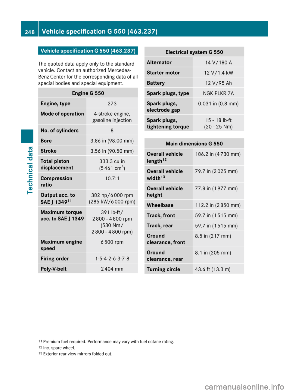
Vehicle specification G 550
(463.237) ...........................................248
Vehicle specification G 55 AMG
(463.271) ...........................................249
Rims and tires ...................................250
Fuels, coolants, lubricants, etc. ......252
245Technical data463_AKB; 2; 52, en-USd2ureepe,Version: 2.11.7.12008-12-02T10:52:11+01:00 - Seite 245
Page 248 of 264
Vehicle equipment
iThis Operator’s Manual describes all
features, standard or optional, potentially
available for your vehicle at the time of
purchase. Please be aware that your
vehicle might not be equipped with all
features described in this manual.
Parts service
All authorized Mercedes-Benz Centers
maintain a stock of Genuine Mercedes-Benz
Parts required for maintenance and repair
work. In addition, strategically located parts
distribution centers provide quick and
reliable parts service.
More than 300 000 different parts for
Mercedes-Benz models are available.
Genuine Mercedes-Benz Parts are subjected
to stringent quality inspections. Each part has
been specifically developed, manufactured or
selected for and adapted to Mercedes-Benz
vehicles.
Therefore, Genuine Mercedes-Benz Parts
should be installed.
! Do not use non-genuine Mercedes-Benz
parts and accessories not authorized by
Mercedes-Benz. Doing so could damage
the vehicle, which is not covered by the
Mercedes-Benz Limited Warranty. Also, it
could compromise the vehicle’s durability
or safety.
Warranty coverage
Your vehicle is covered under the terms of the
warranties printed in the Service and
Warranty Information booklet.
Your authorized Mercedes-Benz Center will
exchange or repair any defective parts
originally installed in the vehicle in
accordance with the terms of the following
warranties:
RNew Vehicle Limited Warranty
REmission System Warranty
REmission Performance Warranty
RCalifornia, Connecticut, Maine,
Massachusetts, New York, Pennsylvania,
Rhode Island, and Vermont Emission
Control Systems Warranty
RState Warranty Enforcement Laws (Lemon
Laws)
Replacement parts and accessories are
covered by the Mercedes-Benz Parts and
Accessories warranties, copies of which are
available at any authorized Mercedes-Benz
Center.
Loss of Service and Warranty
Information booklet
Should you lose your Service and Warranty
Information booklet, have an authorized
Mercedes-Benz Center arrange for a
replacement. It will be mailed to you.
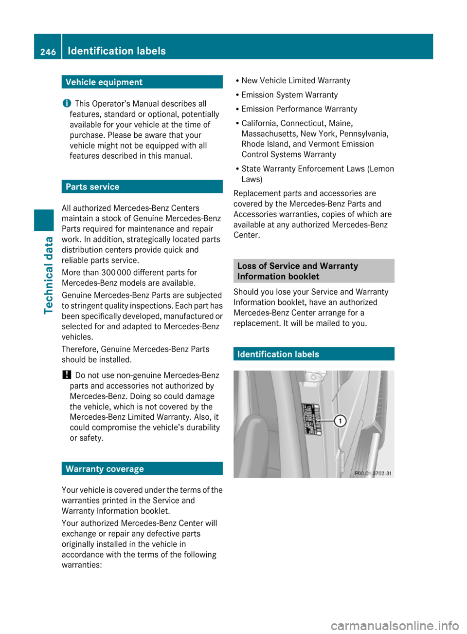
Identification labels
246Identification labelsTechnical data
463_AKB; 2; 52, en-USd2ureepe,Version: 2.11.7.12008-12-02T10:52:11+01:00 - Seite 246
Page 249 of 264
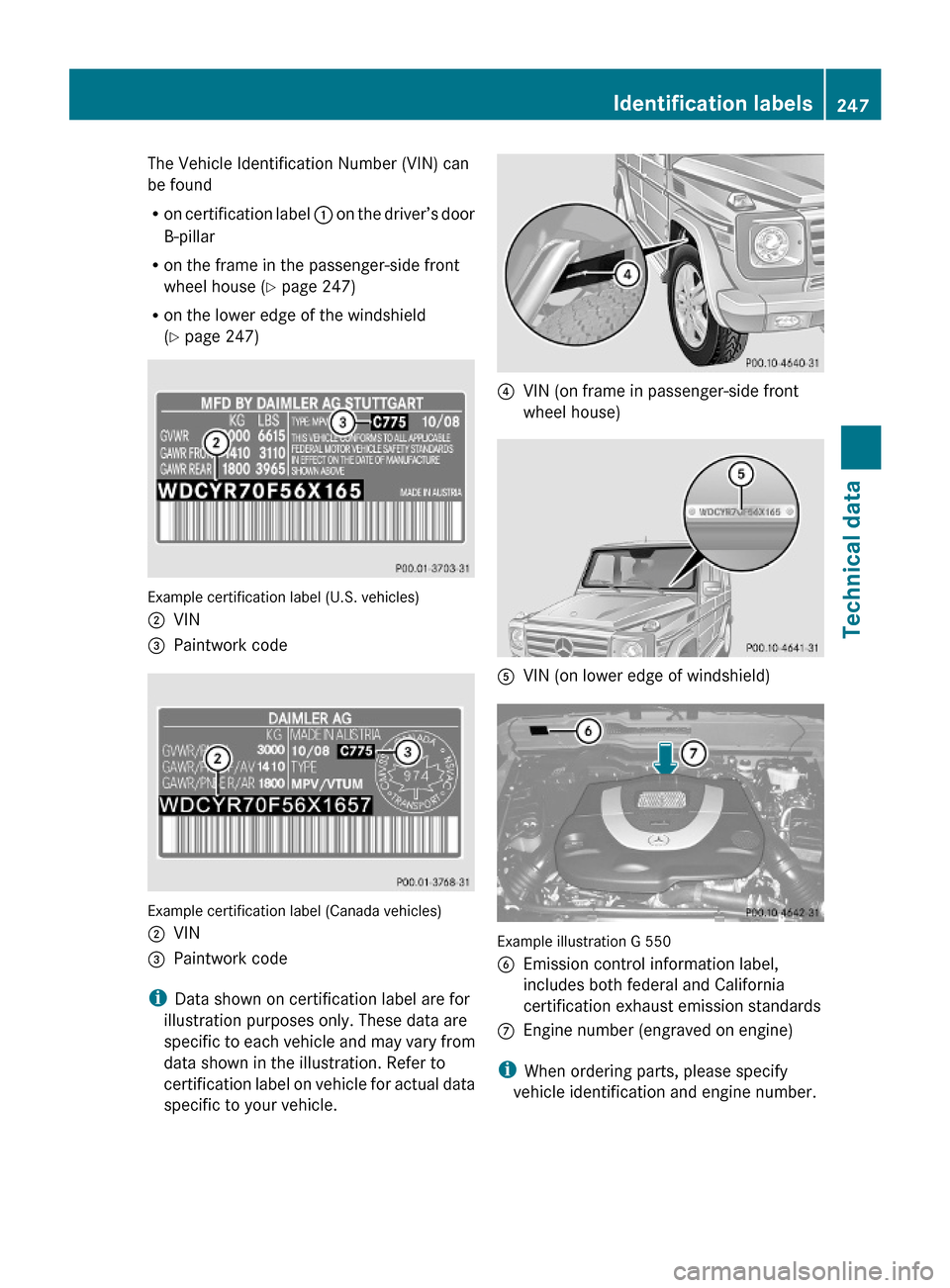
The Vehicle Identification Number (VIN) can
be found
Ron certification label : on the driver’s door
B-pillar
Ron the frame in the passenger-side front
wheel house (Y page 247)
Ron the lower edge of the windshield
(Y page 247)
Example certification label (U.S. vehicles)
;VIN=Paintwork code
Example certification label (Canada vehicles)
;VIN=Paintwork code
iData shown on certification label are for
illustration purposes only. These data are
specific to each vehicle and may vary from
data shown in the illustration. Refer to
certification label on vehicle for actual data
specific to your vehicle.
?VIN (on frame in passenger-side front
wheel house)
AVIN (on lower edge of windshield)
Example illustration G 550
BEmission control information label,
includes both federal and California
certification exhaust emission standards
CEngine number (engraved on engine)
iWhen ordering parts, please specify
vehicle identification and engine number.
Identification labels247Technical data463_AKB; 2; 52, en-USd2ureepe,Version: 2.11.7.12008-12-02T10:52:11+01:00 - Seite 247Z
Page 250 of 264
