MERCEDES-BENZ G-Class 2014 W463 Owner's Manual
Manufacturer: MERCEDES-BENZ, Model Year: 2014, Model line: G-Class, Model: MERCEDES-BENZ G-Class 2014 W463Pages: 354, PDF Size: 7.63 MB
Page 261 of 354
For safety reasons, the rear seat bench must
only be adjusted when the vehicle is
stationary.
Never drive a vehicle with the tailgate open.
Deadly carbon monoxide (CO) gases may
enter vehicle interior resulting in
unconsciousness and death.
! Ensure that you remove all containers
from the cup holder in the rear before
folding the seat backrest and the seat
cushion of the rear bench seat forwards.
Observe the loading guidelines (Y page 256).
The rear bench seat is split symmetrically.
The left-hand and right-hand rear seats can
be folded down to increase the cargo
compartment capacity. The following
changes are possible:
R fold the seat backrests forward
R fold the rear bench seat back fully
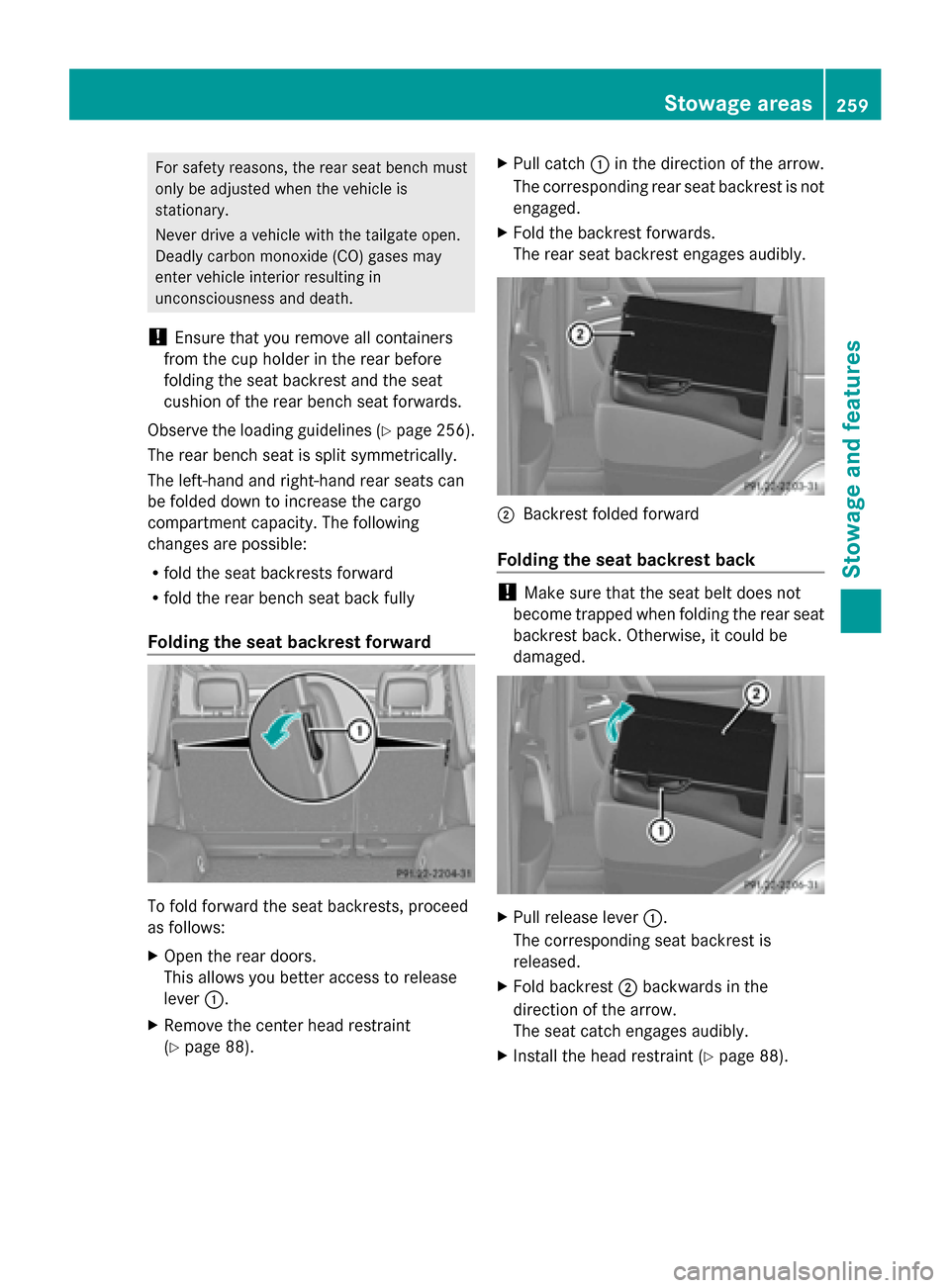
Folding the seat backrest forward To fold forward the seat backrests, proceed
as follows:
X Open the rear doors.
This allows you better access to release
lever 0043.
X Remove the center head restraint
(Y page 88). X
Pull catch 0043in the direction of the arrow.
The corresponding rear seat backrest is not
engaged.
X Fold the backrest forwards.
The rear seat backrest engages audibly. 0044
Backrest folded forward
Folding the seat backrest back !
Make sure that the seat belt does not
become trapped when folding the rear seat
backrest back. Otherwise, it could be
damaged. X
Pull release lever 0043.
The corresponding seat backrest is
released.
X Fold backrest 0044backwards in the
direction of the arrow.
The seat catch engages audibly.
X Install the head restraint (Y page 88). Stowage areas
259Stowage and features Z
Page 262 of 354
Rear bench seat
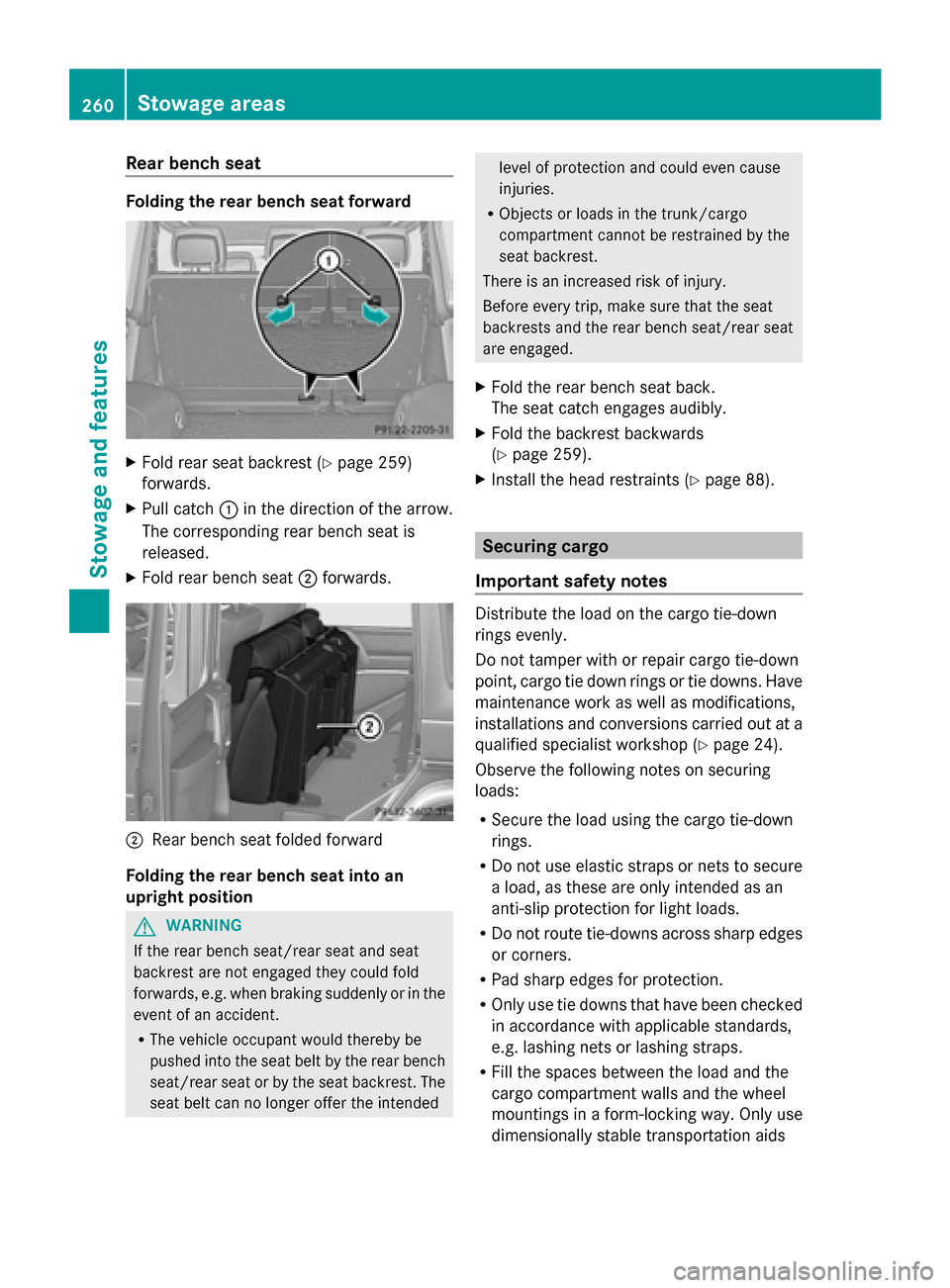
Folding the rear bench seat forward
X
Fold rear seat backrest (Y page 259)
forwards.
X Pull catch 0043in the direction of the arrow.
The corresponding rear bench seat is
released.
X Fold rear bench seat 0044forwards. 0044
Rear bench seat folded forward
Folding the rear bench seat into an
upright position G
WARNING
If the rear bench seat/rear seat and seat
backrest are not engaged they could fold
forwards, e.g. when braking suddenly or in the
event of an accident.
R The vehicle occupant would thereby be
pushed into the seat belt by the rear bench
seat/rear seat or by the seat backrest. The
seat belt can no longer offer the intended level of protection and could even cause
injuries.
R Objects or loads in the trunk/cargo
compartment cannot be restrained by the
seat backrest.
There is an increased risk of injury.
Before every trip, make sure that the seat
backrests and the rear bench seat/rear seat
are engaged.
X Fold the rear bench seat back.
The seat catch engages audibly.
X Fold the backrest backwards
(Y page 259).
X Install the head restraints (Y page 88). Securing cargo
Important safety notes Distribute the load on the cargo tie-down
rings evenly.
Do not tamper with or repair cargo tie-down
point, cargo tie down rings or tie downs. Have
maintenance work as well as modifications,
installations and conversions carried out at a
qualified specialist workshop (Y
page 24).
Observe the following notes on securing
loads:
R Secure the load using the cargo tie-down
rings.
R Do not use elastic straps or nets to secure
a load, as these are only intended as an
anti-slip protection for light loads.
R Do not route tie-downs across sharp edges
or corners.
R Pad sharp edges for protection.
R Only use tie downs that have been checked
in accordance with applicable standards,
e.g. lashing nets or lashing straps.
R Fill the spaces between the load and the
cargo compartment walls and the wheel
mountings in a form-locking way. Only use
dimensionally stable transportation aids 260
Stowage areasStowage and features
Page 263 of 354
for this, such as chocks, wooden fixings or
padding.
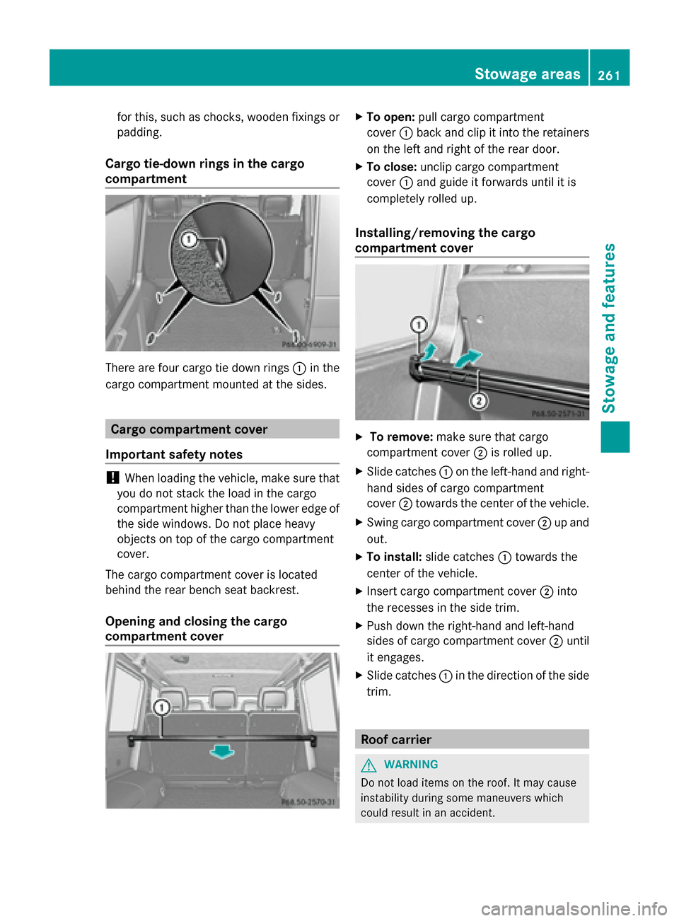
Cargo tie-down rings in the cargo
compartment There are four cargo tie down rings
0043in the
cargo compartment mounted at the sides. Cargo compartment cover
Important safety notes !
When loading the vehicle, make sure that
you do not stack the load in the cargo
compartment higher than the lower edge of
the side windows. Do not place heavy
objects on top of the cargo compartment
cover.
The cargo compartment cover is located
behind the rear bench seat backrest.
Opening and closing the cargo
compartment cover X
To open: pull cargo compartment
cover 0043back and clip it into the retainers
on the left and right of the rear door.
X To close: unclip cargo compartment
cover 0043and guide it forwards until it is
completely rolled up.
Installing/removing the cargo
compartment cover X
To remove: make sure that cargo
compartment cover 0044is rolled up.
X Slide catches 0043on the left-hand and right-
hand sides of cargo compartment
cover 0044towards the center of the vehicle.
X Swing cargo compartment cover 0044up and
out.
X To install: slide catches 0043towards the
center of the vehicle.
X Insert cargo compartment cover 0044into
the recesses in the side trim.
X Push down the right-hand and left-hand
sides of cargo compartment cover 0044until
it engages.
X Slide catches 0043in the direction of the side
trim. Roof carrier
G
WARNING
Do not load items on the roof. It may cause
instability during some maneuvers which
could result in an accident. Stowage areas
261Stowage and features Z
Page 264 of 354
The roof is not suited for transporting loads.
Do not use the roof rails or other accessories
which are mounted on the roof. Features
Cup holder
Important safety notes G
WARNING
In order to help prevent spilling liquids on
vehicle occupants and/or vehicle equipment,
only use containers that fit into the cup
holder. Use lids on open containers and do
not fill containers to a height where the
contents, especially hot liquids, could spill
during braking, vehicle maneuvers, or in an
accident. Liquids spilled on vehicle occupants
may cause serious personal injury. Liquids
spilled on vehicle equipment may cause
damage not covered by the Mercedes-Benz
Limited Warranty.
When not in use, keep the cup holder closed.
An open cup holder may cause injury to you
or others when contacted during braking,
vehicle maneuvers, or in an accident.
Keep in mind that objects placed in the cup
holder may come loose during braking,
vehicle maneuvers, or in an accident and be
thrown around in the vehicle interior. Objects
thrown around in the vehicle interior may
cause an accident and/or serious personal
injury.
Cup holder on the center console X
Fold cup holder 0043all the way up.
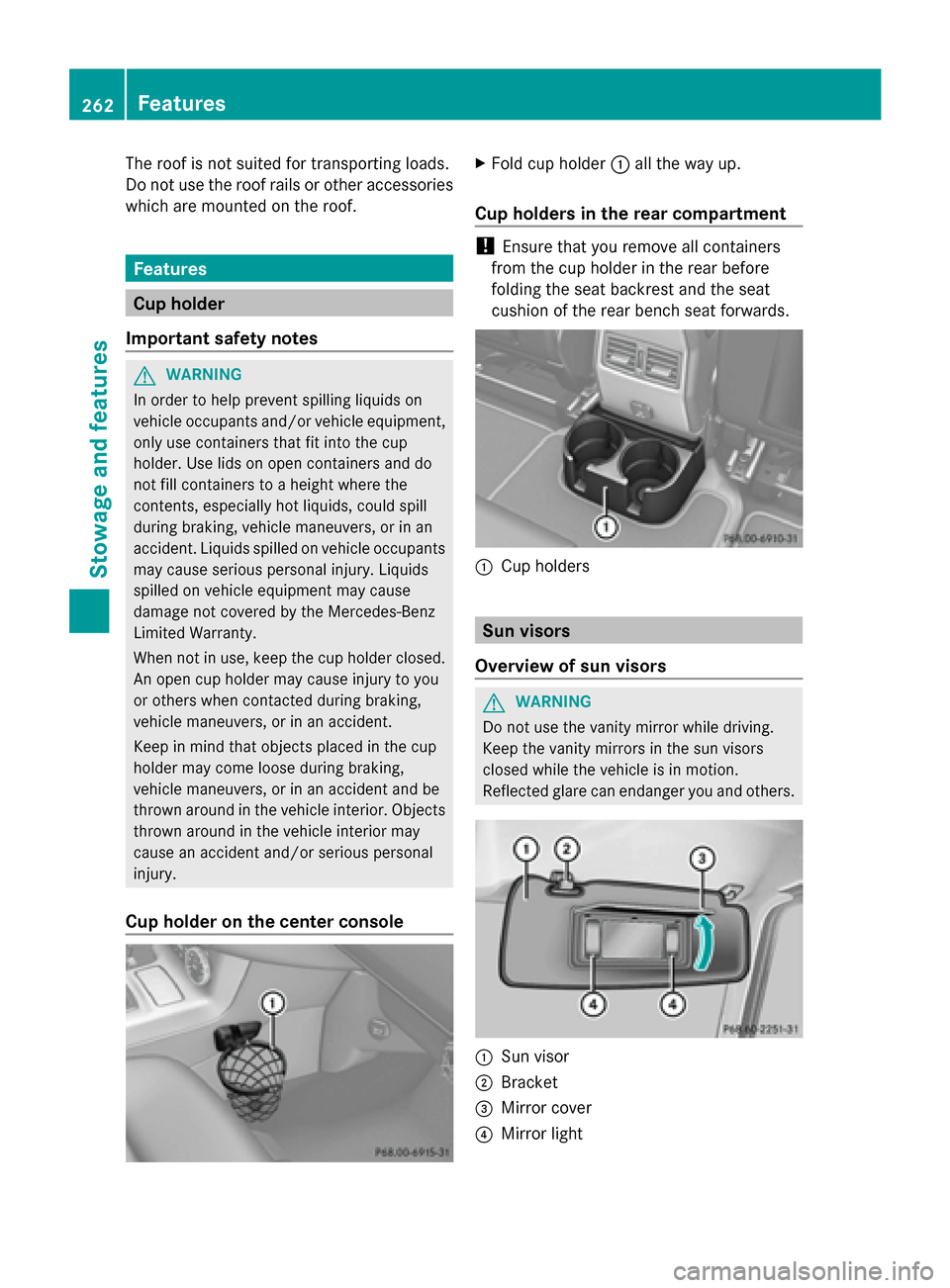
Cup holders in the rear compartment !
Ensure that you remove all containers
from the cup holder in the rear before
folding the seat backrest and the seat
cushion of the rear bench seat forwards. 0043
Cup holders Sun visors
Overview of sun visors G
WARNING
Do not use the vanity mirror while driving.
Keep the vanity mirrors in the sun visors
closed while the vehicle is in motion.
Reflected glare can endanger you and others. 0043
Sun visor
0044 Bracket
0087 Mirror cover
0085 Mirror light 262
FeaturesStowage and features
Page 265 of 354
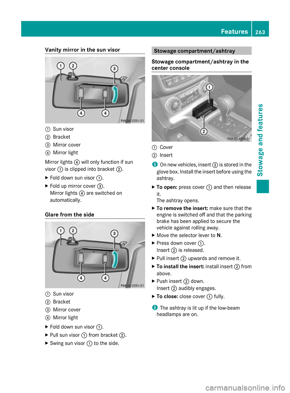
Vanity mirror in the sun visor
0043
Sun visor
0044 Bracket
0087 Mirror cover
0085 Mirror light
Mirror lights 0085will only function if sun
visor 0043is clipped into bracket 0044.
X Fold down sun visor 0043.
X Fold up mirror cover 0087.
Mirror lights 0085are switched on
automatically.
Glare from the side 0043
Sun visor
0044 Bracket
0087 Mirror cover
0085 Mirror light
X Fold down sun visor 0043.
X Pull sun visor 0043from bracket 0044.
X Swing sun visor 0043to the side. Stowage compartment/ashtray
Stowage compartment/ashtray in the
center console 0043
Cover
0044 Insert
i On new vehicles, insert 0044is stored in the
glove box. Install the insert before using the
ashtray.
X To open: press cover 0043and then release
it.
The ashtray opens.
X To remove the insert: make sure that the
engine is switched off and that the parking
brake has been applied to secure the
vehicle against rolling away.
X Move the selector lever to N.
X Press down cover 0043.
Insert 0044is released.
X Pull insert 0044upwards and remove it.
X To install the insert: install insert0044from
above.
X Push insert 0044down.
Insert 0044audibly engages.
X To close: close cover 0043fully.
i The ashtray is lit up if the low-beam
headlamps are on. Features
263Stowage an d features Z
Page 266 of 354
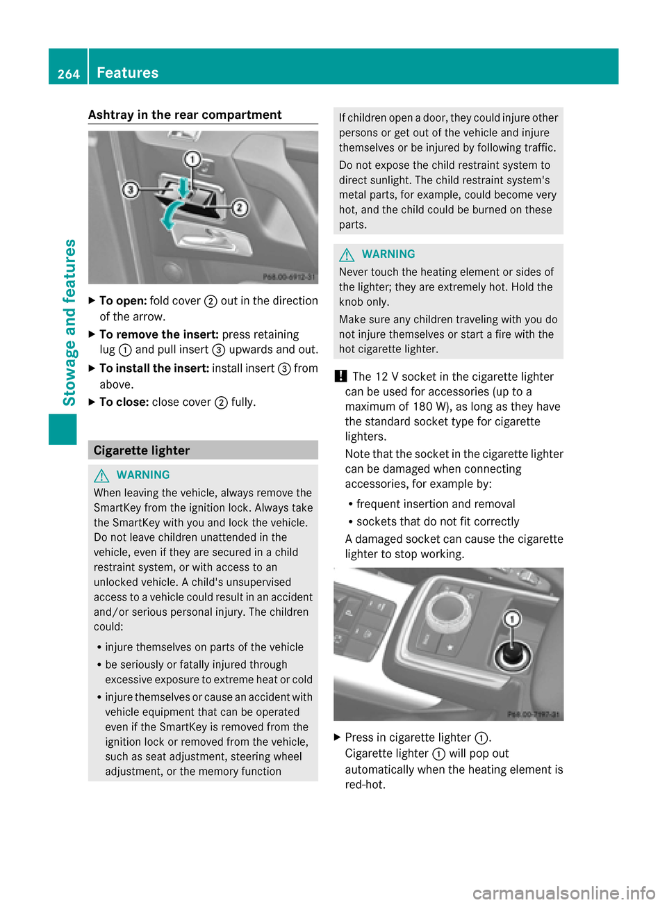
Ashtray in the rear compartment
X
To open: fold cover 0044out in the direction
of the arrow.
X To remove the insert: press retaining
lug 0043and pull insert 0087upwards and out.
X To install the insert: install insert0087from
above.
X To close: close cover 0044fully. Cigarette lighter
G
WARNING
When leaving the vehicle, always remove the
SmartKey from the ignition lock. Always take
the SmartKey with you and lock the vehicle.
Do not leave children unattended in the
vehicle, even if they are secured in a child
restraint system, or with access to an
unlocked vehicle. A child's unsupervised
access to a vehicle could result in an accident
and/or serious personal injury. The children
could:
R injure themselves on parts of the vehicle
R be seriously or fatally injured through
excessive exposure to extreme heat or cold
R injure themselves or cause an accident with
vehicle equipment that can be operated
even if the SmartKey is removed from the
ignition lock or removed from the vehicle,
such as seat adjustment, steering wheel
adjustment, or the memory function If children open a door, they could injure other
persons or get out of the vehicle and injure
themselves or be injured by following traffic.
Do not expose the child restraint system to
direct sunlight. The child restraint system's
metal parts, for example, could become very
hot, and the child could be burned on these
parts. G
WARNING
Never touch the heating element or sides of
the lighter; they are extremely hot. Hold the
knob only.
Make sure any children traveling with you do
not injure themselves or start a fire with the
hot cigarette lighter.
! The 12 V socket in the cigarette lighter
can be used for accessories (up to a
maximum of 180 W), as long as they have
the standard socket type for cigarette
lighters.
Note that the socket in the cigarette lighter
can be damaged when connecting
accessories, for example by:
R frequent insertion and removal
R sockets that do not fit correctly
A damaged socket can cause the cigarette
lighter to stop working. X
Press in cigarette lighter 0043.
Cigarette lighter 0043will pop out
automatically when the heating element is
red-hot. 264
FeaturesStowage and featu
res
Page 267 of 354
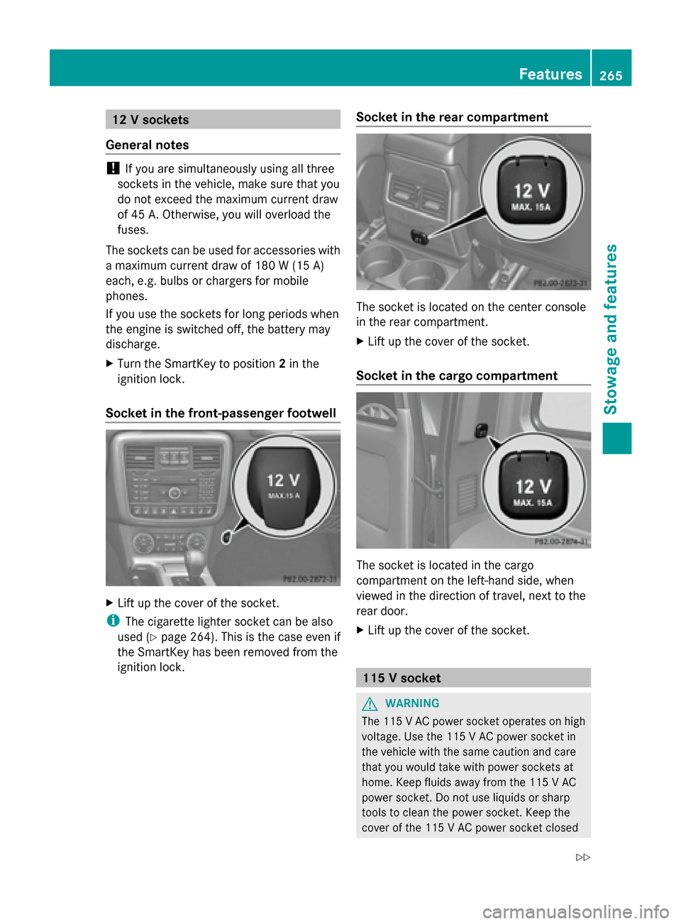
12 V sockets
General notes !
If you are simultaneously using all three
sockets in the vehicle, make sure that you
do not exceed the maximum current draw
of 45 A. Otherwise, you will overload the
fuses.
The sockets can be used for accessories with
a maximum current draw of 180 W (15 A)
each, e.g. bulbs or chargers for mobile
phones.
If you use the sockets for long periods when
the engine is switched off, the battery may
discharge.
X Turn the SmartKey to position 2in the
ignition lock.
Socket in the front-passenger footwell X
Lift up the cover of the socket.
i The cigarette lighter socket can be also
used (Y page 264). This is the case even if
the SmartKey has been removed from the
ignition lock. Socket in the rear compartment The socket is located on the center console
in the rear compartment.
X
Lift up the cover of the socket.
Socket in the cargo compartment The socket is located in the cargo
compartment on the left-hand side, when
viewed in the direction of travel, next to the
rear door.
X
Lift up the cover of the socket. 115 V socket
G
WARNING
The 115 VAC power socket operates on high
voltage. Use the 115 V AC power socket in
the vehicle with the same caution and care
that you would take with power sockets at
home. Keep fluids away from the 115 V AC
power socket. Do not use liquids or sharp
tools to clean the power socket. Keep the
cover of the 115 V AC power socket closed Features
265Stowage and features
Z
Page 268 of 354
when not in use. Otherwise, you could suffer
an electric shock and be seriously or even
fatally injured. G
WARNING
Any device that you connect must have a
suitable plug and meet U.S. standards. Never
pull at a cable to disconnect a plug from a
115 V AC power socket. Never use a damaged
connection cable. The 115 V AC power socket
must never be connected to another 115 V
AC power source. Do not use a converter with
an earthed plug for the 115 V AC power
socket. This could cause serious injury to you
and/or other people. G
WARNING
If the 115 V AC power socket is damaged or
pulled out of the trim, do not use or touch the
115 V AC power socket. The use of a 115 V
AC power socket that has been damaged or
pulled out of the trim could cause serious
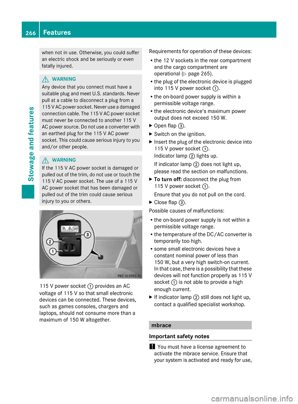
injury to you or others. 115 V power socket
0043provides an AC
voltage of 115 V so that small electronic
devices can be connected. These devices,
such as games consoles, chargers and
laptops, should not consume more than a
maximum of 150 W altogether. Requirements for operation of these devices:
R
the 12 V sockets in the rear compartment
and the cargo compartment are
operational ( Ypage 265).
R the plug of the electronic device is plugged
into 115 V power socket 0043.
R the on-board power supply is within a
permissible voltage range.
R the electronic device's maximum power
output does not exceed 150 W.
X Open flap 0087.
X Switch on the ignition.
X Insert the plug of the electronic device into
115 V power socket 0043.
Indicator lamp 0044lights up.
If indicator lamp 0044does not light up,
please read the section on malfunctions.
X To turn off: disconnect the plug from
115 V power socket 0043.
Ensure that you do not pull on the cord.
X Close flap 0087.
Possible causes of malfunctions:
R the on-board power supply is not within a
permissible voltage range.
R the temperature of the DC/AC converter is
temporarily too high.
R some small electronic devices have a
constant nominal power of less than
150 W, but a very high switch-on current.
In that case, there is a possibility that these
devices will not function properly as 115 V
socket 0043is not able to provide a high
enough current.
X If indicator lamp 0044still does not light up,
contact a qualified specialist workshop. mbrace
Important safety notes !
You must have a license agreement to
activate the mbrace service. Ensure that
your system is activated and ready for use, 266
FeaturesStowage and features
Page 269 of 354
and press the
0051MB Info call button to
register. If one of these steps is not carried
out, it may not be possible to activate the
system.
If you have questions about the activation,
contact one of the following telephone
hotlines:
R USA: Response Center at
1-888-990-9007
R Canada: Customer Service at
1-888-923-8367
USA only : shortly after successfully
registering with the mbrace service a user ID
and password will be sent to you by post. You
can use this password to log onto the mbrace
area under "Owners Online" at http://
www.mbusa.com .
The mbrace system is available if:
R it has been activated and is operational.
Activation requires an available mobile
phone network, a valid SIM card and a
subscription to a security service.
R the battery is sufficiently charged.
R the corresponding mobile phone network
is available for transmitting data to the
Customer Center.
i Determining the location of the vehicle on
a map is only possible if there is sufficient
GPS reception and the vehicle position can
be forwarded to the Customer Center.
The mbrace system To adjust the volume during an mbrace call,
proceed as follows:
X Press the 0081or0082 button on the
multifunction steering wheel.
or
X Use the COMAND volume control.
The mbrace system provides three different
services:
R automatic and manual emergency call
R Roadside Assistance call
R MB Info call USA only:
you can find further information
and a description of all available features
under "Owners Online" at http://
www.mbusa.com.
System self-test G
WARNING
A malfunction in the system has been
detected if one of the following conditions
occurs:
R the indicator lamp in the SOS button does
not light up during the system self-
diagnosis.
R the indicator lamp in the 009FRoadside
Assistance button does not light up during
the system self-diagnosis.
R the indicator lamp in the 0051information
button does not light up during the system
self-diagnosis.
R the indicator lamp in the SOS button,
009F Roadside Assistance button or 0051
information button continues to be lit red
after the system self-diagnosis.
R the Tele Tele Aid
Aidinoperative
inoperative orTele
Tele Aid
Aid
not activated
not activated message appears on the
multifunction display after the system self-
diagnosis.
If a malfunction is indicated as outlined above,
the system may not operate as expected. In
the event of an emergency, assistance must
be summoned by other means.
Have the system checked at the nearest
authorized Mercedes-Benz Center or contact
the following service hotlines:
R USA: Response Center at
1-888-990-9007
R Canada: Customer Service at
1-888-923-8367
After you have switched on the ignition, the
system carries out a self-diagnosis. Features
267Stowage and features Z
Page 270 of 354
Emergency call
Important safety notes
G
WARNING
If the indicator lamp in the SOS button is
flashing continuously and there was no voice
connection to the Response Center
established, then the mbrace system could
not initiate an emergency call (e.g. the
relevant cellular phone network is not
available).
The message Call Failed
Call Failed appears in the
multifunction display for approximately
10 seconds.
Should this occur, assistance must be
summoned by other means.
! You must have a license agreement to
activate the mbrace service. Ensure that
your system is activated and ready for use,
and press the 0051MB Info call button to
register. If one of these steps is not carried
out, it may not be possible to activate the
system.
If you have questions about the activation,
contact one of the following telephone
hotlines:
R USA: Response Center at
1-888-990-9007
R Canada: Customer Service at
1-888-923-8367
An emergency call is dialed automatically if
an air bag or Emergency Tensioning Device is
triggered.
i An automatically dialed mbrace
emergency call cannot be canceled.
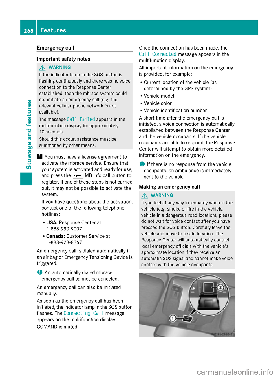
An emergency call can also be initiated
manually.
As soon as the emergency call has been
initiated, the indicator lamp in the SOS button
flashes. The Connecting Call Connecting Call message
appears on the multifunction display.
COMAND is muted. Once the connection has been made, the
Call Connected Call Connected
message appears in the
multifunction display.
All important information on the emergency
is provided, for example:
R Current location of the vehicle (as
determined by the GPS system)
R Vehicle model
R Vehicle color
R Vehicle identification number
A short time after the emergency call is
initiated, a voice connection is automatically
established between the Response Center
and the vehicle occupants. If the vehicle
occupants are able to respond, the Response
Center will attempt to obtain more detailed
information on the emergency.
i If there is no response from the vehicle
occupants, an ambulance is immediately
sent to the vehicle.
Making an emergency call G
WARNING
If you feel at any way in jeopardy when in the
vehicle (e.g. smoke or fire in the vehicle,
vehicle in a dangerous road location), please
do not wait for voice contact after you have
pressed the SOS button. Carefully leave the
vehicle and move to a safe location. The
Response Center will automatically contact
local emergency officials with the vehicle's
approximate location if they receive an
automatic SOS signal and cannot make voice
contact with the vehicle occupants. 268
FeaturesStowage and features