ECU MERCEDES-BENZ G-Class 2015 W463 Workshop Manual
[x] Cancel search | Manufacturer: MERCEDES-BENZ, Model Year: 2015, Model line: G-Class, Model: MERCEDES-BENZ G-Class 2015 W463Pages: 350, PDF Size: 6.44 MB
Page 261 of 350
If you have questions about the activation,
contact one of the following telephone hot-
lines:
R USA: Response Center at
1-888-990-9007
R Canada: Customer Service at
1-888-923-8367
USA only : shortly after successfully register-
ing with the mbrace service a user ID and
password will be sent to you by post. You can use this password to log onto the mbrace area
under "Owners Online" at http://
www.mbusa.com.
The mbrace system is available if:
R it has been activated and is operational.
Activation requires an available mobile
phone network, a valid SIM card and a sub- scription to a security service.
R the battery is sufficiently charged.
R the corresponding mobile phone network is
available for transmitting data to the Cus-
tomer Center.
i Determining the location of the vehicle on
a map is only possible if there is sufficient
GPS reception and the vehicle position can
be forwarded to the Customer Center.
The mbrace system To adjust the volume during an mbrace call,
proceed as follows:
X Press the WorX button on the mul-
tifunction steering wheel.
or X Use the COMAND volume control.
The mbrace system provides three different
services:
R Automatic and manual emergency call
R Roadside Assistance call
R MB Info call
USA only: you can find more information and
a description of all available features under "Owners Online" at
http://
www.mbusa.com.
System self-test G
WARNING
A malfunction in the system has been detec-
ted if one of the following conditions occurs:
R the indicator lamp in the SOS button does
not light up during the system self-diagno-
sis.
R the indicator lamp in the ºRoadside
Assistance button does not light up during
the system self-diagnosis.
R the indicator lamp in the Einformation
button does not light up during the system
self-diagnosis.
R the indicator lamp in the SOS button, º
Roadside Assistance button or Einfor-
mation button continues to be lit red after
the system self-diagnosis.
R the Tele Tele Aid
Aidinoperative
inoperative orTele
Tele Aid
Aid
not activated
not activated message appears on the
multifunction display after the system self-
diagnosis.
If a malfunction is indicated as outlined above,
the system may not operate as expected. In
the event of an emergency, assistance must
be summoned by other means.
Have the system checked at the nearest
authorized Mercedes-Benz Center or contact
the following service hotlines:
R USA: Response Center at
1-888-990-9007
R Canada: Customer Service at
1-888-923-8367
After you have switched on the ignition, the
system carries out a self-diagnosis. Features
259Stowage and features Z
Page 272 of 350
been installed in the garage door remote
control.
R Align the antenna cable of the garage door
opener unit. This can improve signal trans- mission.
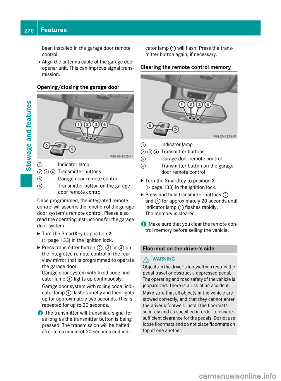
Opening/closing the garage door :
Indicator lamp
;=? Transmitter buttons
A Garage door remote control
B Transmitter button on the garage
door remote control
Once programmed, the integrated remote
control will assume the function of the garage door system's remote control. Please also
read the operating instructions for the garage
door system.
X Turn the SmartKey to position 2
(Y page 133) in the ignition lock.
X Press transmitter button ;,=or? on
the integrated remote control in the rear-
view mirror that is programmed to operate
the garage door.
Garage door system with fixed code: indi-
cator lamp :lights up continuously.
Garage door system with rolling code: indi-
cator lamp :flashes briefly and then lights
up for approximately two seconds. This is
repeated for up to 20 seconds.
i The transmitter will transmit a signal for
as long as the transmitter button is being
pressed. The transmission will be halted
after a maximum of 20 seconds and indi- cator lamp
:will flash. Press the trans-
mitter button again, if necessary.
Clearing the remote control memory :
Indicator lamp
;=? Transmitter buttons
A Garage door remote control
B Transmitter button on the garage
door remote control
X Turn the SmartKey to position 2
(Y page 133) in the ignition lock.
X Press and hold transmitter buttons ;
and ?for approximately 20 seconds until
indicator lamp :flashes rapidly.
The memory is cleared.
i Make sure that you clear the remote con-
trol memory before selling the vehicle. Floormat on the driver's side
G
WARNING
Objects in the driver's footwell can restrict the pedal travel or obstruct a depressed pedal.
The operating and road safety of the vehicle is
jeopardized. There is a risk of an accident.
Make sure that all objects in the vehicle are
stowed correctly, and that they cannot enter
the driver's footwell. Install the floormats
securely and as specified in order to ensure
sufficient clearance for the pedals. Do not use loose floormats and do not place floormats on
top of one another. 270
FeaturesStowage and features
Page 279 of 350
X
Switch off the engine.
X If the engine is at normal operating tem-
perature: wait about five minutes before
carrying out the measurement.
X If the engine is not at normal operating
temperature: e.g. if the engine was only
started briefly, wait approximately
30 minutes before carrying out the meas-
urement.
i If you wish to cancel the measurement,
press the 9or: button on the mul-
tifunction steering wheel.
Adding engine oil G
WARNING
Certain components in the engine compart-
ment, such as the engine, radiator and parts
of the exhaust system, can become very hot.
Working in the engine compartment poses a
risk of injury.
Where possible, let the engine cool down and touch only the components described in the
following. G
WARNING
If engine oil comes into contact with hot com- ponents in the engine compartment, it may
ignite. There is a risk of fire and injury.
Make sure that engine oil is not spilled next to
the filler neck. Let the engine cool down and
thoroughly clean the engine oil off the com-
ponents before starting the engine. H
Environmental note
When adding oil, take care not to spill any. If
oil enters the soil or waterways, it is harmful to the environment.
! Only use engine oils and oil filters that
have been approved for vehicles with a ser-
vice system. You can obtain a list of the
engine oils and oil filters tested and
approved in accordance with the
Mercedes-Benz Specifications for Service Products at any Mercedes-Benz Service
center.
Damage to the engine or exhaust system is
caused by the following:
R using engine oils and oil filters that have
not been specifically approved for the
service system
R replacing engine oil and oil filters after
the interval for replacement specified by
the service system has been exceeded
R using engine oil additives.
! Do not add too much oil. If the oil level is
above the "max" mark on the dipstick, too
much oil has been added. This can lead to
damage to the engine or the catalytic con-
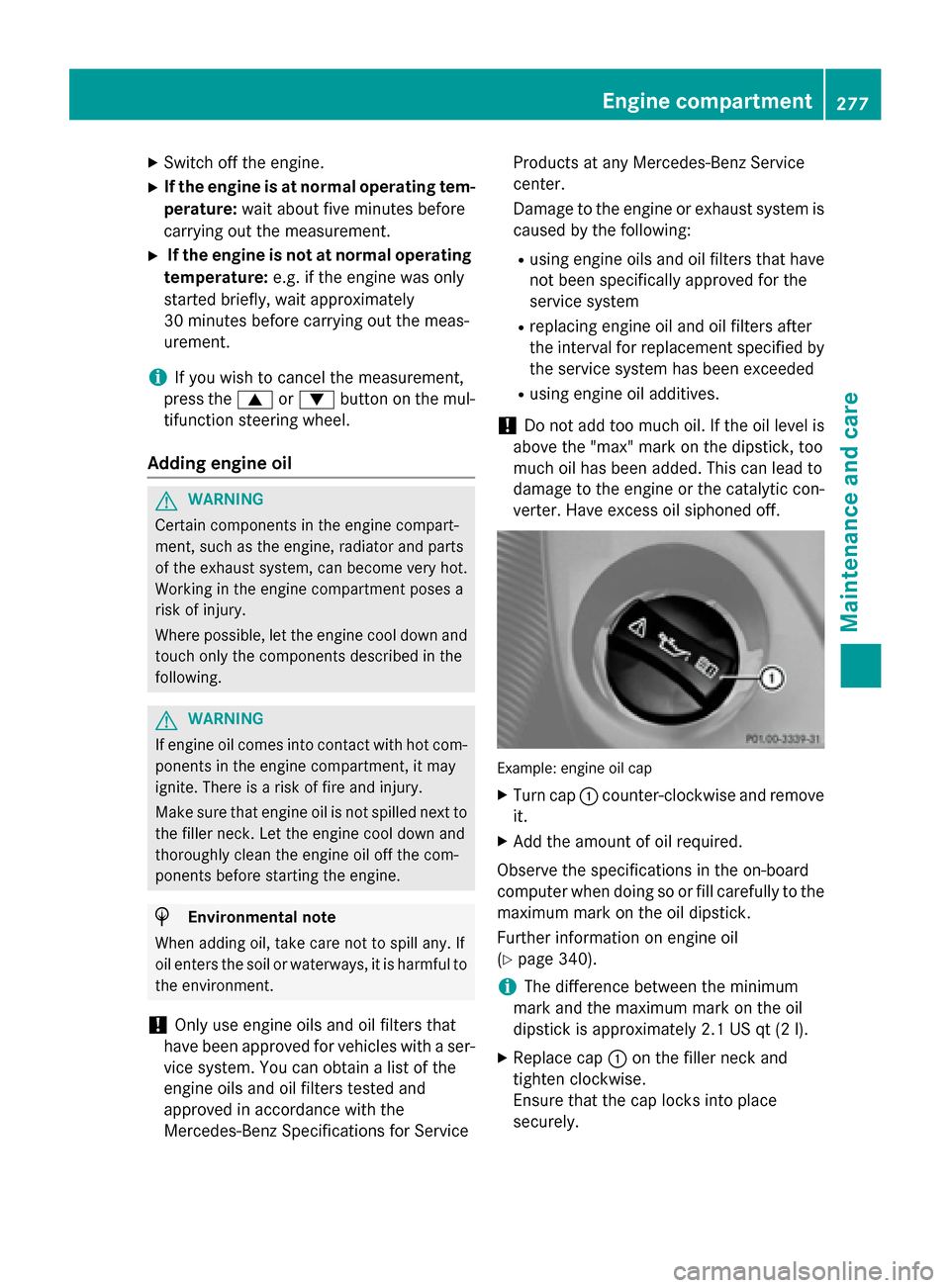
verter. Have excess oil siphoned off. Example: engine oil cap
X Turn cap :counter-clockwise and remove
it.
X Add the amount of oil required.
Observe the specifications in the on-board
computer when doing so or fill carefully to the maximum mark on the oil dipstick.
Further information on engine oil
(Y page 340).
i The difference between the minimum
mark and the maximum mark on the oil
dipstick is approximately 2.1 US qt (2 l).
X Replac e cap:on the filler neck and
tighten clockwise.
Ensure that the cap locks into place
securely. Engine compartment
277Maintenance and care Z
Page 286 of 350
product that is recommended and
approved by Mercedes-Benz.
Cleaning wiper blades G
WARNING
You could become trapped by the windshield wipers if they start moving while cleaning the
windshield or wiper blades. There is a risk of
injury.
Always switch off the windshield wipers and
the ignition before cleaning the windshield or
wiper blades.
! Do not pull the wiper blade. Otherwise,
the wiper blade could be damaged.
! Do not clean wiper blades too often and
do not rub them too hard. Otherwise, the
graphite coating could be damaged. This
could cause wiper noise.
! Hold the wiper arm securely when folding
back. The windshield could be damaged if
the wiper arm smacks against it suddenly.
X Fold the windshield wiper arms away from
the windshield.
X Carefully clean the wiper blades with a
damp cloth.
X Fold the windshield wiper arms back again
before switching on the ignition.
Cleaning the headlamps !
Only use cleaning agents or cleaning
cloths which are suitable for plastic head-
lamp lenses. Unsuitable cleaning agents or cleaning cloths could scratch or damage
the plastic headlamp lenses.
X Clean the headlamp lenses with a damp
sponge and a mild cleaning agent, e.g.
Mercedes-Benz car shampoo or cleaning
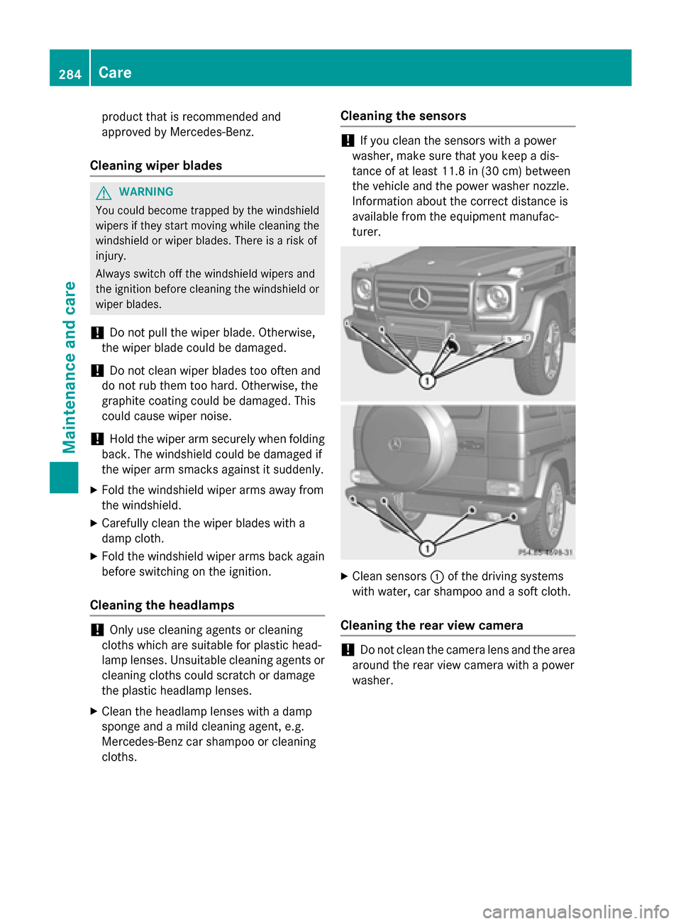
cloths. Cleaning the sensors !
If you clean the sensors with a power
washer, make sure that you keep a dis-
tance of at least 11.8 in (30 cm) between
the vehicle and the power washer nozzle.
Information about the correct distance is
available from the equipment manufac-
turer. X
Clean sensors :of the driving systems
with water, car shampoo and a soft cloth.
Cleaning the rear view camera !
Do not clean the camera lens and the area
around the rear view camera with a power
washer. 284
CareMaintenance and care
Page 294 of 350
i
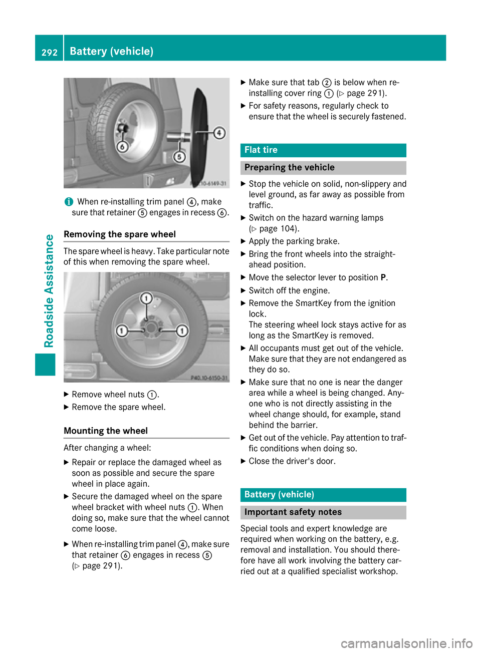
When re-installing trim panel
?, make
sure that retainer Aengages in recess B.
Removing the spare wheel The spare wheel is heavy. Take particular note
of this when removing the spare wheel. X
Remove wheel nuts :.
X Remove the spare wheel.
Mounting the wheel After changing a wheel:
X Repair or replace the damaged wheel as
soon as possible and secure the spare
wheel in place again.
X Secure the damaged wheel on the spare
wheel bracket with wheel nuts :. When
doing so, make sure that the wheel cannot
come loose.
X When re-installing trim panel ?, make sure
that retainer Bengages in recess A
(Y page 291). X
Make sure that tab ;is below when re-
installing cover ring :(Ypage 291).
X For safety reasons, regularly check to
ensure that the wheel is securely fastened. Flat tire
Preparing the vehicle
X Stop the vehicle on solid, non-slippery and
level ground, as far away as possible from
traffic.
X Switch on the hazard warning lamps
(Y page 104).
X Apply the parking brake.
X Bring the front wheels into the straight-
ahead position.
X Move the selector lever to position P.
X Switch off the engine.
X Remove the SmartKey from the ignition
lock.
The steering wheel lock stays active for as
long as the SmartKey is removed.
X All occupants must get out of the vehicle.
Make sure that they are not endangered as they do so.
X Make sure that no one is near the danger
area while a wheel is being changed. Any-
one who is not directly assisting in the
wheel change should, for example, stand
behind the barrier.
X Get out of the vehicle. Pay attention to traf-
fic conditions when doing so.
X Close the driver's door. Battery (vehicle)
Important safety notes
Special tools and expert knowledge are
required when working on the battery, e.g.
removal and installation. You should there-
fore have all work involving the battery car-
ried out at a qualified specialist workshop. 292
Battery (vehicle)Roadside Assistance
Page 296 of 350
!
You should have all work involving the
battery carried out at a qualified specialist
workshop. In the exceptional case that it is
necessary for you to disconnect the battery yourself, make sure that:
R you switch off the engine and remove the
SmartKey. Check that all the indicator
lamps in the instrument cluster are off.
Otherwise, electronic components, such
as the alternator, may be damaged.
R you first remove the negative terminal
clamp and then the positive terminal
clamp. Never swap the terminal clamps.
Otherwise, the vehicle's electronic sys-
tem may be damaged.
R on vehicles with automatic transmission,
the transmission is locked in position P
after disconnecting the battery. The vehi-
cle is secured against rolling away. You
can then no longer move the vehicle.
The battery and the cover of the positive
terminal clamp must be installed securely
during operation. H
Environmental note Batteries contain dangerous
substances. It is against the
law to dispose of them with
the household rubbish. They
must be collected separately
and recycled to protect the
environment. Dispose of batteries in an
environmentally friendly
manner. Take discharged
batteries to a qualified spe-
cialist workshop or a special
collection point for used bat-
teries.
In order for the battery to achieve the maxi-
mum possible service life, it must always be
sufficiently charged.
Comply with safety precautions and take pro-
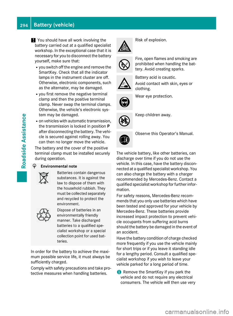
tective measures when handling batteries. Risk of explosion.
Fire, open flames and smoking are
prohibited when handling the bat-
tery. Avoid creating sparks. Battery acid is caustic.
Avoid contact with skin, eyes or
clothing.
Wear eye protection.
Keep children away.
Observe this Operator's Manual.
The vehicle battery, like other batteries, can
discharge over time if you do not use the
vehicle. In this case, have the battery discon-
nected at a qualified specialist workshop. You can also charge the battery with a charger
recommended by Mercedes-Benz. Contact a
qualified specialist workshop for further infor-
mation.
For safety reasons, Mercedes-Benz recom-
mends that you only use batteries which have been tested and approved for your vehicle by
Mercedes-Benz. These batteries provide
increased impact protection to prevent vehi-
cle occupants from suffering acid burns
should the battery be damaged in the event of an accident.
Have the battery condition of charge checked
more frequently if you use the vehicle mainly
for short trips or if you leave it standing idle
for a lengthy period. Consult a qualified spe-
cialist workshop if you wish to leave your
vehicle parked for a long period of time.
i Remove the SmartKey if you park the
vehicle and do not require any electrical
consumers. The vehicle will then use very 294
Battery (vehicle)Roadside Assistance
Page 300 of 350
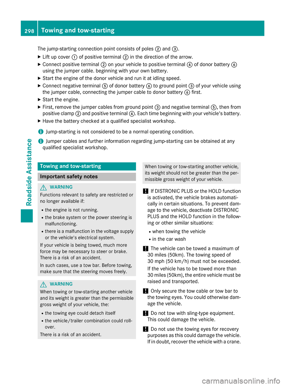
The jump-starting connection point consists of poles
;and =.
X Lift up cover :of positive terminal ;in the direction of the arrow.
X Connect positive terminal ;on your vehicle to positive terminal ?of donor battery B
using the jumper cable. beginning with your own battery.
X Start the engine of the donor vehicle and run it at idling speed.
X Connect negative terminal Aof donor battery Bto ground point =of your vehicle using
the jumper cable, connecting the jumper cable to donor battery Bfirst.
X Start the engine.
X First, remove the jumper cables from ground point =and negative terminal A, then from
positive clamp ;and positive terminal ?. Each time beginning with your vehicle's battery.
X Have the battery checked at a qualified specialist workshop.
i Jump-starting is not considered to be a normal operating condition.
i Jumper cables and further information regarding jump-starting can be obtained at any
qualified specialist workshop. Towing and tow-starting
Important safety notes
G
WARNING
Functions relevant to safety are restricted or
no longer available if:
R the engine is not running.
R the brake system or the power steering is
malfunctioning.
R there is a malfunction in the voltage supply
or the vehicle's electrical system.
If your vehicle is being towed, much more
force may be necessary to steer or brake.
There is a risk of an accident.
In such cases, use a tow bar. Before towing,
make sure that the steering moves freely. G
WARNING
When towing or tow-starting another vehicle
and its weight is greater than the permissible gross weight of your vehicle, the:
R the towing eye could detach itself
R the vehicle/trailer combination could roll-
over.
There is a risk of an accident. When towing or tow-starting another vehicle,
its weight should not be greater than the per- missible gross weight of your vehicle.
! If DISTRONIC PLUS or the HOLD function
is activated, the vehicle brakes automati-
cally in certain situations. To prevent dam-
age to the vehicle, deactivate DISTRONIC
PLUS and the HOLD function in the follow- ing or other similar situations:
R when towing the vehicle
R in the car wash
! The vehicle can be towed a maximum of
30 miles (50km). The towing speed of
30 mph (50 km/h) must not be exceeded.
If the vehicle has to be towed more than
30 miles (50km), the entire vehicle must be
raised and transported.
! Only secure the tow cable or tow bar to
the towing eyes. You could otherwise dam- age the vehicle.
! Do not tow with sling-type equipment.
This could damage the vehicle.
! Do not use the towing eyes for recovery
purposes as this could damage the vehicle.
If in doubt, recover the vehicle with a crane. 298
Towing and tow-startingRoadside Assistance
Page 302 of 350
switch, the hazard warning lamps start
flashing again.
X Turn the SmartKey to position 2in the igni-
tion lock (Y page 133).
X When the vehicle is stationary, depress the
brake pedal and keep it depressed.
X Shift the transfer case to neu-
tral(Y page 188).
X Shift the automatic transmission to posi-
tion N.
X Release the brake pedal.
X Release the parking brake (Y page 151).
i The transmission can only change gear if
the battery has sufficient charge.
If you cannot move the selector lever to N,
the propeller shafts to the driven axles
must be removed. Transporting the vehicle
! You may only secure the vehicle by the
wheels, not by parts of the vehicle such as
axle or steering components. Otherwise,
the vehicle could be damaged.
Use the towing eyes to pull the vehicle if it
needs to be transported on a trailer or trans-
porter (Y page 299).
X Apply the parking brake.
X Turn the SmartKey to position 2in the igni-
tion lock (Y page 133).
X Move the selector lever to N.
X Shift the transfer case to neutral
(Y page 188).
X Secure the towing cable to the towing eyes
(Y page 299).
X Make sure that the vehicle cannot roll
away.
X Release the parking brake.
X Load the vehicle onto the transporter. As soon as the vehicle has been loaded:
X Apply the parking brake.
X Shift the automatic transmission to posi-
tion P.
X Turn the SmartKey to position 0in the igni-
tion lock (Y page 133) and remove it.
X Secure the vehicle. Recovering a vehicle that has become
stuck
! When recovering a vehicle that has
become stuck, pull it as smoothly and
evenly as possible. Excessive tractive
power could damage the vehicles.
If the drive wheels have become stuck in
loose or muddy ground, pull the vehicle out
with extreme caution, especially so if the vehi-
cle is loaded.
Never attempt to recover a stuck vehicle with
a trailer attached.
Pull out the vehicle backwards, if possible
using the tracks it made when it became
stuck. Towing in the event of malfunctions
General notes !
If you are removing the propeller shaft,
use M10 nuts as spacers on the M8 bolts
and secure them with M8 nuts.
New self-locking nuts must be used when
the propeller shafts are refitted.
X Observe the safety notes as you do so
(Y page 298).
i Consult an authorized Mercedes-Benz
Center. 300
Towing and tow-startingRoadside Assistance
Page 314 of 350
Avoid tire pressures that are too low in all the
tires, including the spare wheel.
Underinflated tires may: R overheat, leading to tire defects
R have an adverse effect on handling charac-
teristics
R wear quickly and unevenly
R have an adverse effect on fuel consumption
Overinflation G
WARNING
Tires with excessively high pressure can burst
because they are damaged more easily by
road debris, potholes etc. In addition, they
also suffer from irregular wear, which can
severely impair the braking properties and the driving characteristics. There is a risk of an
accident.
Avoid tire pressures that are too high in all the
tires, including the spare wheel.
Overinflated tires may: R increase the braking distance
R have an adverse effect on handling charac-
teristics
R wear quickly and unevenly
R have an adverse effect on ride comfort
R be more susceptible to damage
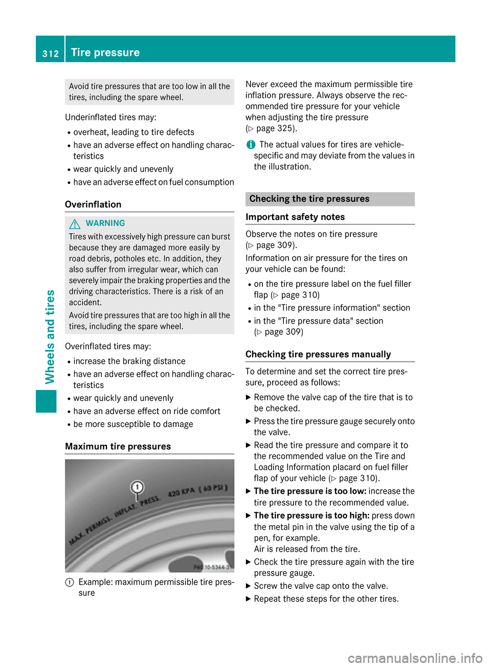
Maximum tire pressures :
Example: maximum permissible tire pres-
sure Never exceed the maximum permissible tire
inflation pressure. Always observe the rec-
ommended tire pressure for your vehicle
when adjusting the tire pressure
(Y page 325).
i The actual values for tires are vehicle-
specific and may deviate from the values in
the illustration. Checking the tire pressures
Important safety notes Observe the notes on tire pressure
(Y page 309).
Information on air pressure for the tires on
your vehicle can be found:
R on the tire pressure label on the fuel filler
flap (Y page 310)
R in the "Tire pressure information" section
R in the "Tire pressure data" section
(Y page 309)
Checking tire pressures manually To determine and set the correct tire pres-
sure, proceed as follows:
X Remove the valve cap of the tire that is to
be checked.
X Press the tire pressure gauge securely onto
the valve.
X Read the tire pressure and compare it to
the recommended value on the Tire and
Loading Information placard on fuel filler
flap of your vehicle (Y page 310).
X The tire pressure is too low: increase the
tire pressure to the recommended value.
X The tire pressure is too high: press down
the metal pin in the valve using the tip of a
pen, for example.
Air is released from the tire.
X Check the tire pressure again with the tire
pressure gauge.
X Screw the valve cap onto the valve.
X Repeat these steps for the other tires. 312
Tire pressureWheels and tires
Page 328 of 350

Maximum loaded vehicle weight
The maximum weight is the sum of:
R
the curb weight of the vehicle
R the weight of the accessories
R the load limit
R the weight of the factory installed optional
equipment
Kilopascal (kPa) Metric unit for tire pressure. 6.9 kPa corre-
sponds to 1 psi. Another unit for tire pressure
is bar. 100 kilopascals (kPa) are the equiva-
lent of 1 bar.
Load index In addition to the load-bearing index, the load
index may also be imprinted on the sidewall of
the tire. This specifies the load-bearing capa- city more precisely.
Curb weight The weight of a vehicle with standard equip-
ment including the maximum capacity of fuel,
oil and coolant. It also includes the air-condi- tioning system and optional equipment if
these are installed in the vehicle, but does notinclude passengers or luggage.
Maximum load rating The maximum load rating is the maximum
permissible weight in kilograms or lbs for
which a tire is approved.
Maximum permissible tire pressure Maximum permissible tire pressure for one
tire.
Maximum load on one tire Maximum load on one tire. This is calculated
by dividing the maximum axle load of one axle
by two. PSI (pounds per square inch) A standard unit of measure for tire pressure.
Aspect ratio Relationship between tire height and tire
width in percent.
Tire pressure This is pressure inside the tire applying an
outward force to each square inch of the tire's surface. The tire pressure is specified in
pounds per square inch (psi), in kilopascals
(kPa) or in bar. The tire pressure should only
be corrected when the tires are cold.
Cold tire pressure The tires are cold:
R if the vehicle has been parked without
direct sunlight on the tires for at least three
hours and
R if the vehicle has not been driven further
than 1 mile (1.6 km)
Tread The part of the tire that comes into contact
with the road.
Bead The tire bead ensures that the tire sits
securely on the wheel. There are several steel
wires in the bead to prevent the tire from
coming loose from the wheel rim.
Sidewall The part of the tire between the tread and the
bead.
Weight of optional extras The combined weight of those optional extras
that weigh more than the replaced standard
parts and more than 2.3 kg (5 lbs). These
optional extras, such as high-performance 326
Tire labelingWheels and tires