fuses MERCEDES-BENZ G-Class 2016 W463 Owner's Manual
[x] Cancel search | Manufacturer: MERCEDES-BENZ, Model Year: 2016, Model line: G-Class, Model: MERCEDES-BENZ G-Class 2016 W463Pages: 302, PDF Size: 7.04 MB
Page 9 of 302
Drive programAutomati c...................................... 12 3
Displa y.......................................... .119
SETUP (on-board computer) .......... 182
Driving in mountainous terrain
Approach/departure angle ............ 140
Driving downhill .............................1 40
Gradient-climbing capability
(maximum) ..................................... 140
Driving lamps
see Daytime running lamps
Driving off-road
see Off-road driving
Driving on flooded roads .................. 135
Driving safety systems
4ETS (Electronic Traction Sys-
tem) ................................................. 57
ABS (Anti-lock Braking System) ....... 55
ADAPTIVE BRAKE .............................5 9
Adaptive brake lights ....................... 56
BAS (Brake Assist System) .............. 56
Electronic brake force distribu-
tion .................................................. 58
ESP
®(Electronic Stability Pro-
gram) ............................................... 57
Important safety information ........... 55
Overview .......................................... 55
Driving systems
Blind Spot Assist ............................ 154
Cruise control ................................ 141
Display message ............................ 195
DISTRONIC PLUS ...........................147
HOLD function ............................... 157
PARKTRONIC ................................. 158
Rear view camera .......................... 161
SPEEDTRONIC ............................... 145
Variable SPEEDTRONIC ................. 145
Driving tips
Automatic transmission ................. 121
Brakes ...........................................1 33
DISTRONIC PLUS ........................... 153
Downhill gradient ........................... 133
Driving in winter .............................1 36
Driving on flooded roads ................ 135
Driving on sand .............................. 139
Driving over obstacles ................... 139
G
eneral .......................................... 132
Gravel roads .................................. 139 Hydroplaning ................................. 135
Icy road surfaces ........................... 136
Off-road driving .............................. 137
Off-road fording .............................1
35
Snow chains .................................. 264
Tire ruts ......................................... 139
Towing a trailer .............................. 166
Traveling uphill ............................... 140
Wet road surface ........................... 134
DVD audio
Operating (on-board computer) ..... 176
DVD video
Operating (on-board computer) ..... 176
E
EASY-ENTRY featureActivating/deactivating ................. 181
Function/notes ................................ 79
EASY-EXIT feature
Function/notes ................................ 79
Switching on/off ........................... 181
EBD (electronic brake force distri-
bution)
Display message ............................ 186
Function/notes ................................ 58
ECO start/stop function
Deactivating/activating ................. 114
General information ....................... 114
Electrical fuses
Fuse box in the cargo compart-
ment .............................................. 261
Electronic Stability Program
see ESP
®(Electronic Stability Program)
Electronic Traction System
see 4ETS (Electronic Traction System)
Emergency
Automatic measures after an acci-
dent ................................................. 46
Emergency call
see mbrace
Emergency locking
Vehicle ............................................. 66
Emergency release
Vehicle ............................................. 66
Emergency Tensioning Devices
Activation ......................................... 43
Index7
Page 11 of 302
Front-passenger footwell ............... 260
Transmission tunnel ....................... 260
Fuse extractor ................................... 259
Fuses
Allocation chart ............................. 259
Before changing ............................. 259
Dashboard fuse box ....................... 259
Fuse allocation chart ..................... 259
Fuse box in the front-passenger
footwell .......................................... 260
Fuse box in the transmission tun-
nel ................................................. 260
Important safety notes .................. 259
In the battery case ......................... 260
G
Garage door openerClearing the memory ..................... 234
General notes ................................ 231
Important safety notes .................. 231
Opening/closing the garage doo r..2 34
Programming the remote control ... 231
Gasoline ............................................. 290
Gear indicator (on-board com-
puter) ..................................................1 82
Gear or selector lever (cleaning
guidelines) ......................................... 246
Genuine parts ...................................... 19
Genuine wood trim and trim strips
(cleaning instructions) ......................246
Glove box ...........................................2 15
Gradient-climbing capability (max-
imum) ................................................. 140
GTW (Gross Trailer Weight) (defini-
tion) .................................................... 279
H
Hazard warning lamps ........................ 89
Head restraints
Adjusting ......................................... 74
Adjusting (rear) ................................ 75
Installing/removing (rear) ................ 75
Luxury .............................................. 75
Resetting (front) ............................... 75
see NECK-PRO head restraints
see NECK-PRO luxury head restraints Headlamps
Adding fluid to cleaning system ..... 239
Cleaning ......................................... 244
Cleaning system (function) .............. 87
Cleaning system (notes) ................ 295
Fogging up ....................................... 89
Protective grille ................................ 95
see Automatic headlamp mode
Heating
see Climate control
High-beam headlamps
Display message ............................ 190
Switching on/off .............................. 88
Hill start assist .................................. 114
HOLD function
Function/notes .............................1 57
Hood
Closing ...........................................2 36
Display message ............................ 201
Important safety notes .................. 235
Opening ......................................... 236
Horn ...................................................... 26
Hydroplaning ..................................... 135
I
Immobilizer.......................................... 59
Instrument cluster
Overview ........................................ 171
Warning and indicator lamps ......... 202
Instrument cluster lighting .............. 171
Interior lighting
Automatic control ............................ 90
Cargo compartment lamp ................ 91
Delayed switch-off (on-board
computer) ...................................... 180
Manual control ................................. 90
Overview .......................................... 89
Reading lamp ................................... 89
Rear interior lighting ........................ 92
J
JackPump lever ..................................... 283
Storage location ............................ 248
Using ............................................. 282
Jump starting (engine) ......................254
Index9
Page 16 of 302
Service menu (on-board com-
puter).................................................. 178
Service products
Brake fluid .....................................2 93
Coolant (engine) ............................ 294
Engine oil ....................................... 292
Fuel ................................................ 289
Important safety notes .................. 289
Notes ............................................. 289
Refrigerant (air-conditioning sys-
tem) ............................................... 293
Washer fluid ................................... 295
Setting a speed limit
see SPEEDTRONIC
Setting the air distribution ...............105
Settings
Calling up a stored setting ...............8 3
Factory (on-board computer) ......... 181
On-board computer ....................... 178
SETUP (on-board computer) ............. 182
Shift ranges ....................................... 123
Side impact air bag ............................. 42
Side marker lamp (display mes-
sage) ................................................... 191
Side marker lamps (changing
bulbs) .................................................... 94
Side windows
Convenience closing feature ............ 69
Convenience opening feature .......... 68
Important safety information ........... 68
Opening/closing .............................. 68
Overview .......................................... 68
Troubleshooting ............................... 69
Ski rack .............................................. 220
Sliding sunroof
Important safety notes .................... 69
Opening/closing .............................. 70
Operating manually .......................... 70
Problem (malfunction) ..................... 71
SmartKey
Changing the battery ....................... 62
Changing the programming ............. 61
Checking the battery ....................... 62
Convenience closing feature ............ 69
Convenience opening feature .......... 68
Display message ............................ 202
Door central locking/unlocking ....... 60 Important safety notes .................... 60
Loss ................................................. 63
Malfunction ...................................... 63
Mechanical key ................................ 61
Ove
rview .......................................... 60
P
roblem (malfunction) ..................... 63
Starting the engine ........................ 113
Snow chains ...................................... 264
Sockets
Front-passenger footwell ............... 223
Luggage compartment ................... 223
Rear compartment ......................... 223
SOS
see mbrace
Spare fuses ........................................ 259
Spare wheel
Mounting ....................................... 281
Notes/data .................................... 286
Spare wheel bracket at the rear .... 249
Stainless-steel spare hub cap ........ 249
Special seat belt retractor .................. 47
Specialist workshop ............................ 23
Speed, controlling
see Cruise control
Speedometer
Digital ............................................ 174
In the Instrument cluster ............... 171
Segments ...................................... 171
Selecting the unit of measure-
ment .............................................. 179
see Instrument cluster
SPEEDTRONIC
Display message ............................ 197
Selecting ........................................ 145
Variable ......................................... 145
Standing lamps
Display message ............................ 191
Switching on/off .............................. 87
Starting the engine
Important safety notes .................. 113
Steering (display message) .............. 202
Steering wheel
Adjusting (electrically) ..................... 78
Buttons (on-board computer) ......... 172
Cleaning ......................................... 246
Important safety notes .................... 78
Paddle shifters ............................... 123
14Index
Page 153 of 302
iWhen changing lanes, DISTRONIC PLUS
monitors the left lane on left-hand drive vehi-
cles and the right lane on right-hand drive
vehicles.
Stopping
GWARNING
When leaving the vehicle, even if it is braked
only by DISTRONIC PLUS, it could roll away if:
Rthere is a malfunction in the system or in
the voltage supply.
RDISTRONIC PLUS has been deactivated
with the cruise control lever, e.g. by a vehi-
cle occupant or from outside the vehicle.
Rthe electrical system in the engine com-
partment, the battery or the fuses have
been tampered with.
Rthe battery is disconnected.
Rthe accelerator pedal has been depressed, e.g. by a vehicle occupant.
There is a risk of an accident.
If you wish to exit the vehicle, always turn off
DISTRONIC PLUS and secure the vehicle
against rolling away.
If DISTRONIC PLUS detects that the vehicle in
front is stopping, it brakes your vehicle until it is stationary.
Once your vehicle is stationary, it remains sta-
tionary and you do not need to depress the
brake.
iDepending on the specified minimum dis-
tance, your vehicle will come to a standstill at
a sufficient distance behind the vehicle in
front. The specified minimum distance is set
using the control on the cruise control lever.
On steep uphill or downhill inclines or if there is
a malfunction, the transmission may also auto-
matically be shifted into position P.
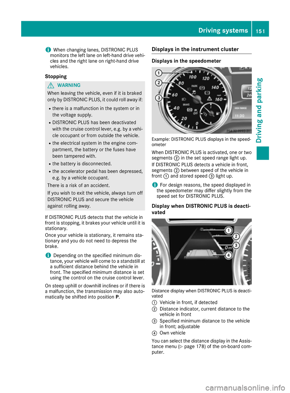
Displays in the instrument cluster
Displays in the speedometer
Example: DISTRONIC PLUS displays in the speed-
ometer
When DISTRONIC PLUS is activated, one or two
segments ;in the set speed range light up.
If DISTRONIC PLUS detects a vehicle in front,
segments ;between speed of the vehicle in
front :and stored speed =light up.
iFor design reasons, the speed displayed in
the speedometer may differ slightly from the
speed set for DISTRONIC PLUS.
Display when DISTRONIC PLUS is deacti-
vated
Distance display when DISTRONIC PLUS is deacti-
vated
:
Vehicle in front, if detected
;Distance indicator, current distance to the
vehicle in front
=Specified minimum distance to the vehicle
in front; adjustable
?Own vehicle
You can select the distance display in the Assis- tance menu (
Ypage 178) of the on-board com-
puter.
Driving systems151
Driving and parking
Z
Page 159 of 302
HOLD function
General notes
The HOLD function can assist the driver in the
following situations:
Rwhen pulling away, especially on steep slopes
Rwhen maneuvering on steep slopes
Rwhen waiting in traffic
The vehicle is kept stationary without the driver having to depress the brake pedal.
The braking effect is canceled and the HOLD
function deactivated when you depress the
accelerator pedal to pull away.
iDo not use the HOLD function when driving
off-road, on steep uphill or downhill gradients
or on slippery or loose surfaces. The HOLD
function cannot hold the vehicle on such sur-
faces.
Activation conditions
You can activate the HOLD function if:
Rthe vehicle is stationary
Rthe engine is running or if it has been auto-
matically switched off by the ECO start/stop
function
Rthe engine is running
Rthe driver's door is closed or your seat belt is
fastened
Rthe transmission is in position D,R or N
RDISTRONIC PLUS is deactivated
Activating the HOLD function
The vehicle's brakes are applied when the HOLD
function is activated. For this reason, deactivate
the HOLD function while in the car wash or while
towing.
XMake sure that the activation conditions are
met.
XDepress the brake pedal.
XQuickly depress the brake pedal further until
ë appears in the multifunction display.
The HOLD function is activated. You can
release the brake pedal.
iIf depressing the brake pedal the first time
does not activate the HOLD function, wait
briefly and then try again.
Deactivating the HOLD function
GWARNING
When leaving the vehicle, it can still roll away despite being braked by the HOLD function if:
Rthere is a malfunction in the system or in
the voltage supply.
Rthe HOLD function has been deactivated by
pressing the accelerator pedal or the brake
pedal, e.g. by a vehicle occupant.
Rthe electrical system in the engine com-
partment, the battery or the fuses have
been tampered with.
Rthe battery is disconnected
There is a risk of an accident.
If you wish to exit the vehicle, always turn off the HOLD function and secure the vehicle
against rolling away.
The HOLD function is deactivated automatically if:
Ryou accelerate and the transmission is in
position Dor R.
Ryou shift the transmission to position P.
Ryou depress the brake pedal again with a cer-
tain amount of pressure untilëdisap-
pears from the multifunction display.
Ryou activate DISTRONIC PLUS.
On steep uphill or downhill gradients or if there
is a malfunction, the transmission may also be
automatically shifted into position P.
Permanent all-wheel drive
!
Never tow the vehicle with one axle raised.
This may damage the transfer case. Damage
of this sort is not covered by the Mercedes-
Benz Limited Warranty. All wheels must
remain either on the ground or be fully raised.
Observe the instructions for towing the vehi-
cle with all wheels in full contact with the
ground.
!When testing the parking brake, operate the
vehicle only briefly (for a maximum of ten sec-
onds) on a brake test dynamometer. When
doing this, turn the SmartKey to position 0or
1 in the ignition. Failure to do this can cause
damage to the drive train or the brake system.
Driving systems157
Driving and parking
Z
Page 225 of 302
XPress in cigarette lighter:.
Cigarette lighter :will pop out automatically
when the heating element is red-hot.
12 V sockets
General notes
!If you are simultaneously using all three
sockets in the vehicle, make sure that you do
not exceed the maximum current draw of
45 A. Otherwise, you will overload the fuses.
The sockets can be used for accessories with a
maximum current draw of 180 W (15 A) each,
e.g. bulbs or chargers for mobile phones.
If you use the sockets for long periods when the
engine is switched off, the battery may dis-
charge.
XTurn the SmartKey to position 2in the ignition
lock.
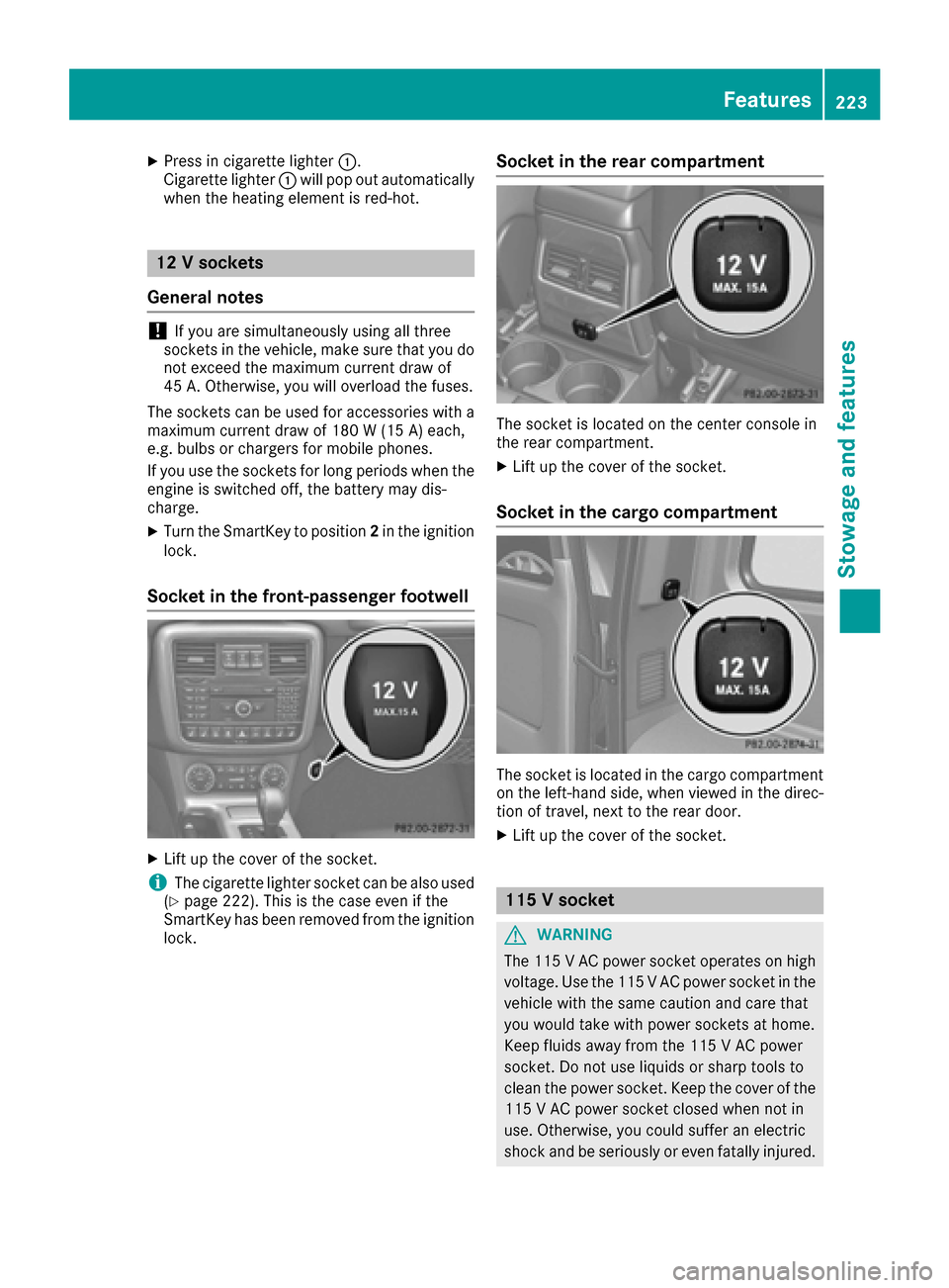
Socket in the front-passenger footwell
XLift up the cover of the socket.
iThe cigarette lighter socket can be also used
(Ypage 222). This is the case even if the
SmartKey has been removed from the ignition
lock.
Socket in the rear compartment
The socket is located on the center console in
the rear compartment.
XLift up the cover of the socket.
Socket in the cargo compartment
The socket is located in the cargo compartment
on the left-hand side, when viewed in the direc-
tion of travel, next to the rear door.
XLift up the cover of the socket.
115 V socket
GWARNING
The 115 VAC power socket operates on high
voltage. Use the 115 V AC power socket in the
vehicle with the same caution and care that
you would take with power sockets at home.
Keep fluids away from the 115 V AC power
socket. Do not use liquids or sharp tools to
clean the power socket. Keep the cover of the
115 V AC power socket closed when not in
use. Otherwise, you could suffer an electric
shock and beseriously or even fat allyinjured.
Features223
Stowage and features
Z
Page 261 of 302
In the event of damage to the front axle
Haveth epropelle rshaf tbetween th erear axl e
and th etransfer cas eremoved.
Hav eth evehicl etowed wit hth efron taxl e
raised.
In the event of damage to the rear axle
Hav eth epropelle rshaf tbetween th efron taxl e
and th etransfer cas eremoved.
Hav eth evehicl etowed wit hth erear axl eraised
and wit hwhee lroller sunder th efron taxle.
Tow-starting (emergency engine
starting)
!
Vehicles wit hautomatic transmission must
no tbe tow-started. You could otherwise dam-
age th eautomatic transmission .
You can fin dinformation on "Jump-starting "
under (
Ypage 254).
Fuses
Important safety notes
GWARNIN G
If you manipulat eor bridge afault yfus eor if
you replace it wit h afusewit h a higher amper-
age, th eelectric cables could be overloaded.
This could result in afire. Ther eis aris kof an
acciden tand injury.
Always replace fault yfuses wit hth especifie d
ne wfuses having th ecorrec tamperage .
!Only use fuses that hav ebeen approve dfor
Mercedes-Ben zvehicles and whic hhave th e
correc tfus erating for th esystem concerned.
Otherwise, component sor systems could be
damaged.
The fuses in your vehicl eserve to close down
fault ycircuits. If afus eblows ,all th ecompo -
nent son th ecircuit and their function sstop
operating .
Blown fuses must be replace dwit hfuses of th e
sam erating ,whic hyou can recognize by th e
color and value .The fus erating sare listed in th e
fus eallocation chart .
iIfafus ehas blown ,contact abreakdown
servic eor an authorize dMercedes-Ben zCen -
ter.
If anewly inserted fus ealso blows ,hav eth e
caus etrace dand rectifie dat aqualified special-
ist workshop, e.g. an authorize dMercedes-Ben z
Center.
Before changing a fuse
XPark th evehicl eand apply th eparking brake.
XSwitc hoff all electrical consumers.
XRemove th eSmartKey from th eignition lock.
All indicator lamp sin th einstrumen tcluste r
must be off .
The fuses are locate din various fus eboxes:
RMain fus ebox on th edriver' sside of th edash -
boar d
RFusebox in th efront-passenger footwell
RFus ebox in th etransmission tunne l
RFusebox in th ebattery cas e
RFusebox in th ecargo compartmen t
The fus eallocation chart and th espar efuses are
in th emain fus ebox on th edashboar d
(
Ypage 259).
You will fin dth efus eremoval device in th evehi-
cle tool kit (
Ypage 248).
Dashboard fuse box
!
Do no tuse apointe dobjec tsuc has ascrew-
driver to open th ecover in th edashboard. You
could damag eth edashboar dor th ecover .
!Makesur ethat no moisture can ente rth e
fus ebox when th ecover is open .
!When closingth ecover ,mak esur ethat it is
lyin gcorrectl yon th efus ebox .Moistur eseep -
ing in or dirt could otherwise impair th eoper -
ation of th efuses.
Fuses259
Breakdown assistance
Z
Page 262 of 302
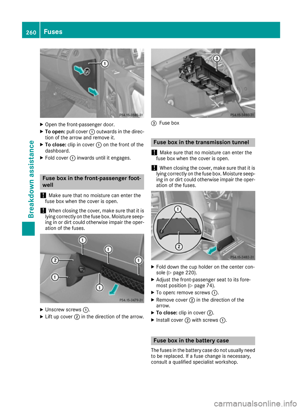
XOpen the front-passenger door.
XTo open:pull cover :outwards in the direc-
tion of the arrow and remove it.
XTo close: clip in cover :on the front of the
dashboard.
XFold cover :inwards until it engages.
Fuse box in the front-passenger foot-
well
!
Make sure that no moisture can enter the
fuse box when the cover is open.
!When closing the cover, make sure that it is
lying correctly on the fuse box. Moisture seep-
ing in or dirt could otherwise impair the oper-
ation of the fuses.
XUnscrew screws :.
XLift up cover;in the direction of the arrow.
=Fuse box
Fuse box in the transmission tunnel
!
Make sure that no moisture can enter the
fuse box when the cover is open.
!When closing the cover, make sure that it is
lying correctly on the fuse box. Moisture seep-
ing in or dirt could otherwise impair the oper-
ation of the fuses.
XFold down the cup holder on the center con-
sole (Ypage 220).
XAdjust the front-passenger seat to its fore-
most position (Ypage 74).
XTo open: remove screws :.
XRemove cover;in the direction of the
arrow.
XTo close: clip in cover ;.
XInstall cover ;with screws :.
Fuse box in the battery case
The fuses in the battery case do not usually need
to be replaced. If a fuse change is necessary,
consult a qualified specialist workshop.
260Fuses
Breakdown assistance
Page 263 of 302
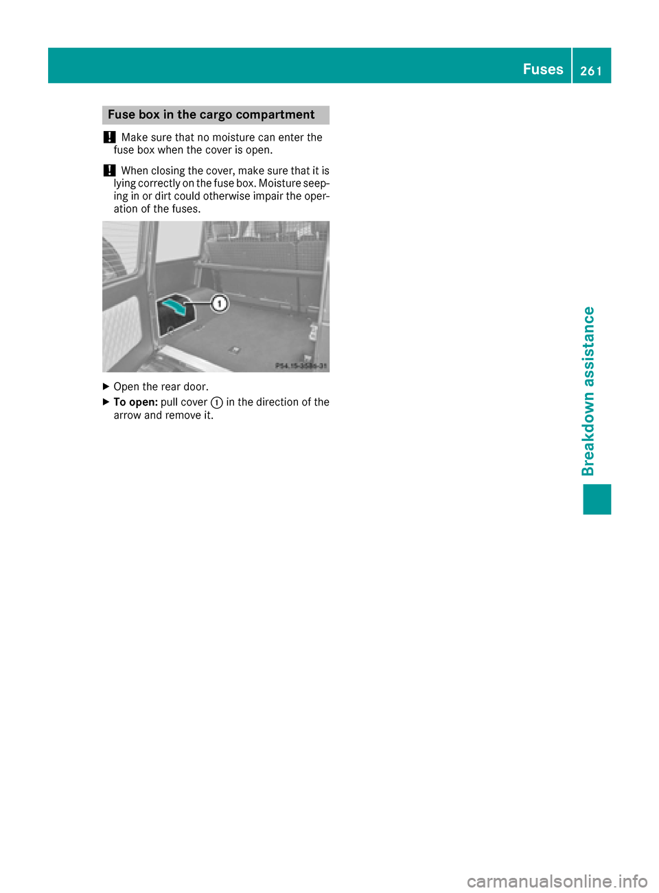
Fuse box in the cargo compartment
!
Mak esure that no moisture can ente rth e
fus ebox when th ecover is open .
!When closingth ecover ,mak esure that it is
lyin gcorrectly on th efus ebox .Moistur eseep -
ing in or dirt could otherwise impair th eoper -
ation of th efuses.
XOpen th erear door .
XTo open:pull cover :in th edirection of th e
arrow and remove it .
Fuses261
Breakdown assistance
Z