MERCEDES-BENZ G-CLASS 2018 Owner's Manual
Manufacturer: MERCEDES-BENZ, Model Year: 2018, Model line: G-CLASS, Model: MERCEDES-BENZ G-CLASS 2018Pages: 294, PDF Size: 4.86 MB
Page 151 of 294
You can also use the rear view camera to select
a 180° view.
When PARKTRONIC is operational (
Ypage 144),
a symbol for your own vehicle appears in the
multimedia system. If the PARKTRONIC warning
displays are active, warning displays =light up
in the multimedia system in yellow or red
accordingly.
Off-road driving systems
Transfer case
General notes
The vehicle has permanent all-wheel drive. The
front and rear axles are constantly driven.
For further information on driving off-road, see
(
Ypage 129).
Shift ranges
HIGH
RANGEPosition for all normal on-
road driving conditions
LOW RANGEOff-road gear for driving off-
road.
Also for use on steep uphill or
downhill gradients, especially
when towing a trailer.
The vehicle travels around
half the speed of on-road driv-
ing range HIGH RANGE. The
tractive power is correspond-
ingly higher.
Shifting the transfer case
General notes
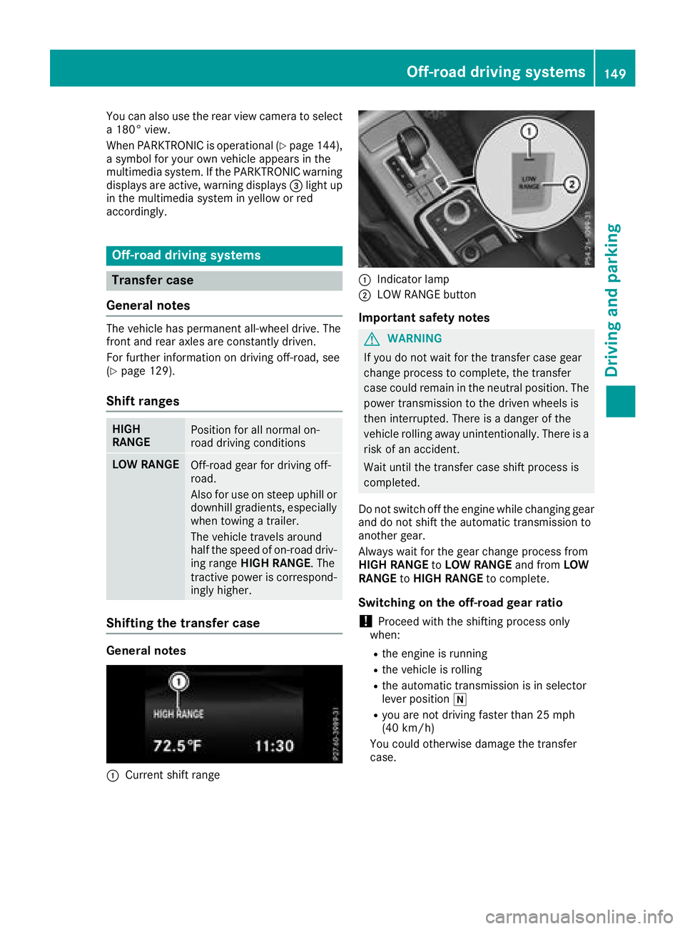
:Current shift range
:Indicator lamp
;LOW RANGE button
Important safety notes
GWARNING
If you do not wait for the transfer case gear
change process to complete, the transfer
case could remain in the neutral position. The power transmission to the driven wheels is
then interrupted. There is a danger of the
vehicle rolling away unintentionally. There is a
risk of an accident.
Wait until the transfer case shift process is
completed.
Do not switch off the engine while changing gear
and do not shift the automatic transmission to
another gear.
Always wait for the gear change process from
HIGH RANGE toLOW RANGE and fromLOW
RANGE toHIGH RANGE to complete.
Switching on the off-road gear ratio
!Proceed with the shifting process only
when:
Rthe engine is running
Rthe vehicle is rolling
Rthe automatic transmission is in selector
lever position i
Ryou are not driving faster than 25 mph
(40 km/h)
You could otherwise damage the transfer
case.
Off-road driving systems149
Driving and parking
Z
Page 152 of 294
XMake sure the ECO start/stop function is
switched off (Ypage 108).
XPress LOW RANGE button;.
Once the shifting procedure has been com-
pleted, the LOW RANGE
transfer case position
is shown in the multifunction display.
Indicator lamp :lights up.
XShift the automatic transmission to position
h.
Switching off the off-road gear ratio
GWARNING
If you do not wait for the transfer case gear
change process to complete, the transfer
case could remain in the neutral position. The power transmission to the driven wheels is
then interrupted. There is a danger of the
vehicle rolling away unintentionally. There is a
risk of an accident.
Wait until the transfer case shift process is
completed.
!Proceed with the shifting process only
when:
Rthe engine is running
Rthe vehicle is rolling
Rthe automatic transmission is in selector
lever position i
Ryou are not driving faster than 43 mph
(70 km/h)
You could otherwise damage the transfer
case.
XPress button ;.
Once the shifting procedure has been com-
pleted, the HIGH
RANGEtransfer case position
is shown in the multifunction display.
Indicator lamp :goes out.
If the shifting procedure is unsuccessful, the
multifunction display may show the following
messages:
RTC Shift Conditions Not Fulfilled
You have not met one or more shift condi-
tions.
RTC NEUTRAL On
The transfer case has canceled the shifting
procedure and is in Neutral.
RTC Shift Canceled
The transfer case has canceled the gear
change process.
XCarry out the gear change process again.
Make sure to meet all conditions for changing
gears.
RTC Malfunction Visit Workshop
There is a malfunction in the transfer case.
XDo not shift the transfer case.
XHave the vehicle checked as soon as possible
at a qualified specialist workshop.
Shifting to neutral
GWARNING
If you do not wait for the transfer case gear
change process to complete, the transfer
case could remain in the neutral position. The power transmission to the driven wheels is
then interrupted. There is a danger of the
vehicle rolling away unintentionally. There is a
risk of an accident.
Wait until the transfer case shift process is
completed.
XTurn the SmartKey to position 2in the igni-
tion lock.
XApply the parking brake.
XDepress the brake pedal.
XShift the automatic transmission to position
i.
XPress and hold LOW RANGE button ;for
approximately ten seconds.
When the shift procedure is complete, the
multifunction display shows the TC
NEUTRALOnmessage for five seconds.
If the shifting procedure is unsuccessful, the
multifunction display may show the following
messages (
Ypage 183).
If the transfer case is in Neutral, the SmartKey
is in the ignition lock and you open the driver's
door, the TC NEUTRAL On
message appears in
the multifunction display. If you then release the
parking brake, a warning tone will sound.
150Off-road driving systems
Driving and parking
Page 153 of 294
Differential locks
General notes
GWARNING
Whe nth edifferential locks are engaged, ABS,
4ETS ,ES P
®and BA Sare deactivated. As a
result ,th ewheels could loc kwhen braking
and th ebraking distanc eis increased. There is
a ris kof an accident.
Disengage th edifferential locks immediately
on fir msurfaces wit hgoo dgrip.
!In order to avoid damage to th etransfe r
case, you mus toperat eth evehicle on adyna-
mometer (1-axl edynamometer) only if:
Rth eaxl eno tdriven on is jacked up
or
Rth ecorrespondin gpropeller shaft is dis -
connecte dand th etransfe rcas edifferen -
tial loc kis engaged.
Differential locks improve th etraction of th e
vehicle.
Your vehicle is equipped wit h adifferential loc k
eac hfor:
Rth etransfe rcase: this controls th ebalance
between th efron tand rea raxles.
Rth erea raxle: this controls th ebalance
between th ewheels on th erea raxle.
Rth efron taxle: this controls th ebalance
between th ewheels on th efron taxle.
Information on differential gea rsyste m
an ddifferential lock
Whe nth evehicle drives around acurve, th e
wheels on th eoutsid eof th ecurve mus tcover a
greater distance. Therefore, th ewheels turn
more rapidly than on th einside. The differential,
a gear syste min th edrive train ,allow sfo rdif -
ferin grotational speeds and facilitates corner-
ing.
The disadvantage of adifferential is that th e
wheels that hav eth eleas tgrip, get th emost
drive. Fo rexample, awhee lon adrive axl elies
on snow-covered groun dand therefore has no
traction .The differential sends most of th edrive
forc eto this whee lbecause th eforc etake sth e
rout eof th elowest resistance. The opposite
whee lon this axle, however, whic hstand son
fir m groun dand could therefore allow propul- sion, receives no drivin
gpower. 4ETS compen-
sates fo rthis disadvantage. 4ETS provides goo d
steerability by automatically braking th espin-
ning wheel. 4ETS provides th ewhee lon th efir m
surfac ewit hmore drive force, whic hin turn pro -
vides propulsion .
ES P
®and 4ETS are traction systems that are
idea lfo rroad drivin gand suitable fo rligh toff-
road driving. The LOW RANGEoff-road g
ear
also improves off-road capability.
Mor echallengin goff-road condition srequire
additional measures suc has locking on eor
more differential.
Your vehicle is equipped wit hthree differential
locks :
Rforth etransfe rcas e
Rforth efron taxl e
Rforth erea raxl e
Each differential loc kcan be engage dwit hth e
correspondin gswitch on th ecenter console. If
th edifferential in th etransfe rcas eis locked, th e
fron tand rea rwheels rotate at th esam espeed.
If th edifferential fo rth erea raxl eis locked, bot h
rea rwheels rotate at th esam espeed, regard -
les sof their respective torque. Note, engaging
th edifferential loc kgreatly impairs th evehicle' s
steerability.
Note, it is imperative to use th edifferential func-
tion when drivin gon fir mroad surfaces. Under
no circumstances should th edifferential be
locke dwhen drivin gon fir mroad surfaces. Oth-
erwise ,th evehicle may no tbe steerable and you
could los econtro lof th evehicle. Therefore, only
engage th edifferential loc kwhen drivin goff-
road. You should only engage th edifferential
loc kif act ivati
n
g4ETS and ES P®drivingsystems
and LOW RANGE off-road gear prove to be
insufficient.
Engaging th edifferential lock s
General notes
The switches are located on th ecenter console.
Off-road driving systems15 1
Driving an d parking
Z
Page 154 of 294
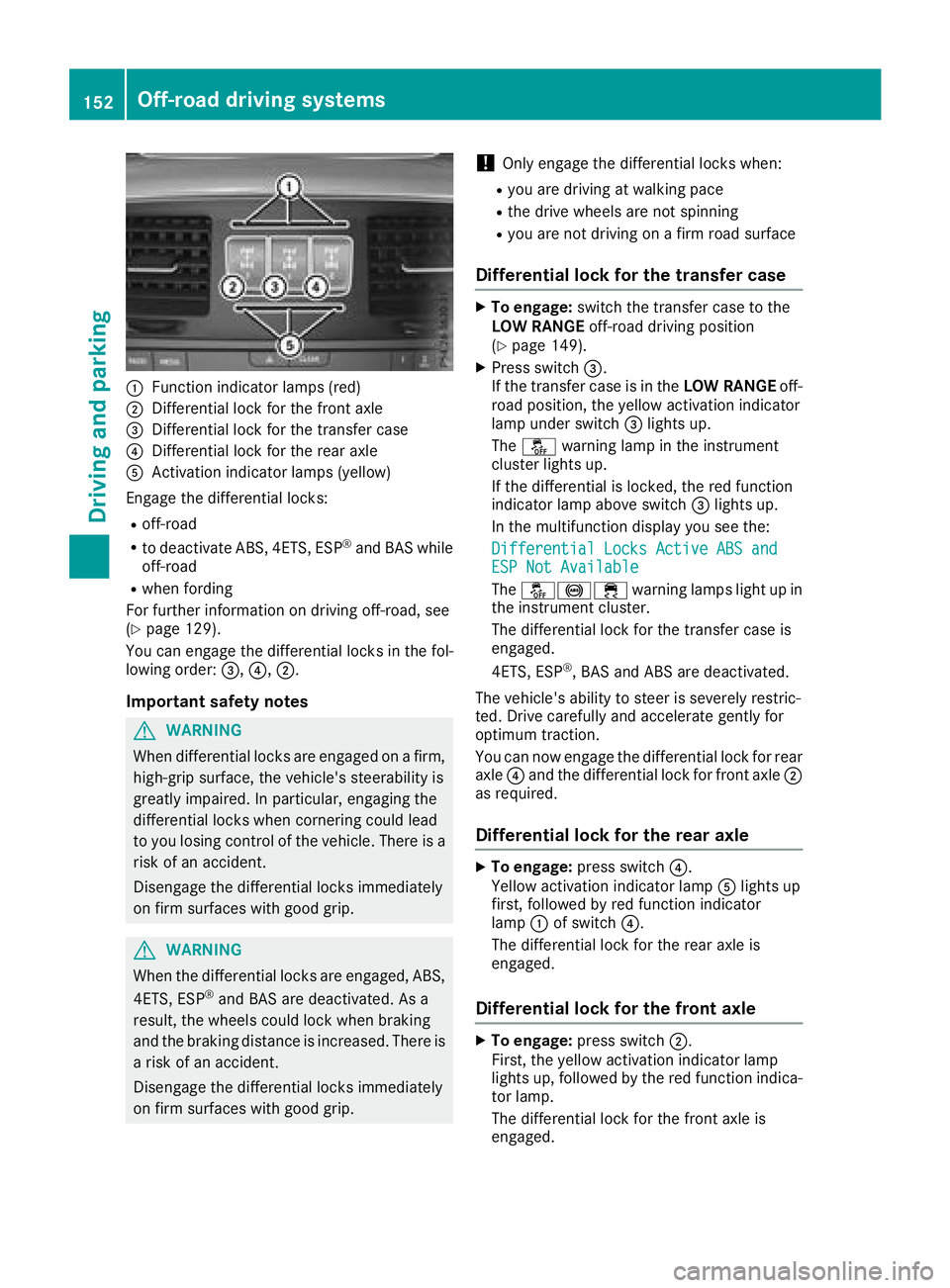
:Function indicator lamps (red)
;Differential lock for the front axle
=Differential lock for the transfer case
?Differential lock for the rear axle
AActivation indicator lamps (yellow)
Engage the differential locks:
Roff-road
Rto deactivate ABS, 4ETS, ESP®and BAS while
off-road
Rwhen fording
For further information on driving off-road, see
(
Ypage 129).
You can engage the differential locks in the fol-
lowing order: =,?,;.
Important safety notes
GWARNING
When differential locks are engaged on a firm,
high-grip surface, the vehicle's steerability is
greatly impaired. In particular, engaging the
differential locks when cornering could lead
to you losing control of the vehicle. There is a risk of an accident.
Disengage the differential locks immediately
on firm surfaces with good grip.
GWARNING
When the differential locks are engaged, ABS, 4ETS, ESP
®and BAS are deactivated. As a
result, the wheels could lock when braking
and the braking distance is increased. There is
a risk of an accident.
Disengage the differential locks immediately
on firm surfaces with good grip.
!Only engage the differential locks when:
Ryou are driving at walking pace
Rthe drive wheels are not spinning
Ryou are not driving on a firm road surface
Differential lock for the transfer case
XTo engage: switch the transfer case to the
LOW RANGE off-road driving position
(
Ypage 149).
XPress switch =.
If the transfer case is in the LOW RANGEoff-
road position, the yellow activation indicator
lamp under switch =lights up.
The å warning lamp in the instrument
cluster lights up.
If the differential is locked, the red function
indicator lamp above switch =lights up.
In the multifunction display you see the:
Differential Locks Active ABS and
ESP Not Available
The å!÷ warning lamps light up in
the instrument cluster.
The differential lock for the transfer case is
engaged.
4ETS, ESP
®, BAS and ABS are deactivated.
The vehicle's ability to steer is severely restric-
ted. Drive carefully and accelerate gently for
optimum traction.
You can now engage the differential lock for rear
axle ?and the differential lock for front axle ;
as required.
Differential lock for the rear axle
XTo engage: press switch ?.
Yellow activation indicator lamp Alights up
first, followed by red function indicator
lamp :of switch ?.
The differential lock for the rear axle is
engaged.
Differential lock for the front axle
XTo engage: press switch ;.
First, the yellow activation indicator lamp
lights up, followed by the red function indica-
tor lamp.
The differential lock for the front axle is
engaged.
152Off-road driving systems
Driving and parking
Page 155 of 294
Disengaging thedifferential lock s
You can disengage th edifferential locks in th e
followin gorder :; ,? ,= .
XTo simultaneously disengage all differen-
tial locks: press switch =.
Yellow activation indicator lamp sA and red
function indicator lamp s: go out .
Afte rapproximately three seconds of normal
driving, ABS, 4ETS ,ES P
®and BA Sare activa-
ted.
The Differential Locks Active ABS
and ESP Not Availablemessag edisap-
pear sin th emultifunction display and th e
å!÷warning lamps in the instru-
ment cluster go out.
XShift the transfer case to the HIGH RANGE
on-road position (Ypage 149).
If red function indicator lamps :do not go out
when disengaging the differential locks, stop
the vehicle safely in accordance with the traffic
conditions and then drive on. The load change
can disengage the differential locks.
Towing a trailer
Important safety notes
GWARNING
When the vehicle/trailer combination begins
to lurch, you could lose control of it. The vehi- cle/trailer combination could even rollover.
There is a risk of an accident.
On no account should you attempt to
straighten up the vehicle/trailer combination
by increasing the speed. Reduce vehicle
speed and do not countersteer. Apply the
brake as necessary.
GWARNING
If you install a ball coupling other than the one
delivered with the vehicle, the trailer tow hitch
and the rear axle may be overloaded. This
applies especially if the ball coupling in ques-
tion is longer or angled differently. This could
seriously impair the driving characteristics
and the trailer can come loose. There is a risk
of an accident.
Only install the ball coupling delivered with
the vehicle or a ball coupling that is designed to meet your trailer towing requirements. Do
not modify the ball coupling or the trailer tow
hitch.
GWARNING
If the ball coupling is not installed correctly or not secured with the bolt provided and the
corresponding spring cotter, the trailer may
come loose. There is a risk of an accident.
Always install and secure the ball coupling as
described. Before every journey, ensure that
the ball coupling is secured with the bolt and
the corresponding spring cotter.
!If you have a trailer tow hitch retrofitted,
changes to the engine cooling system may be
necessary, depending on the vehicle type.
If you have a trailer tow hitch retrofitted,
observe the anchorage points on the chassis
frame.
The installation of a trailer tow hitch is only per-
missible if a towing weight is specified in your
vehicle documents. If this is not the case, then
the vehicle is not approved for the towing of a
trailer.
For more information, please contact a qualified
specialist workshop.
Please observe the manufacturer's operating
instructions for the trailer coupling if a detach-
able trailer coupling is used.
Exceeding the maximum permissible nose-
weight of the trailer drawbar on the ball coupling may cause damage.
Damage may be caused to the following:
RTowing vehicle
RTrailer
RBall coupling
RTrailer tow hitch
The vehicle/trailer combination could become
unstable.
If the noseweight used is lower than the mini-
mum permissible noseweight, the vehicle/
trailer combination could also become unstable.
Towing a trailer153
Driving and parking
Z
Page 156 of 294
To avoid hazardous situations:
Rmake sure to check the noseweight before
each journey
Ruse a drawbar noseweight as close as possi-
ble to the maximum noseweight
Rdo not exceed the maximum permissible
noseweight
Rthe noseweight must not be lower than the
minimum permissible noseweight
Make sure that the following values are not
exceeded:
Rthe permissible trailer drawbar noseweight
Rthe permissible trailer load
Rthe permissible rear axle load of the towing
vehicle
Rthe maximum permissible gross vehicle
weight of both the towing vehicle and the
trailer
When backing up the vehicle towards the trailer,
make sure there is nobody between the trailer
and the vehicle.
The applicable permissible values, which must
not be exceeded, can be found:
Rin your vehicle documents
Ron the type plate for the trailer
Ron the vehicle identification plate
If the values differ, the lowest value applies.
You will find the values approved by the manu-
facturer on the vehicle identification plates and
those for the towing vehicle under "Technical
data" (
Ypage 291).
When backing up the vehicle towards the trailer,
make sure there is nobody between the trailer
and the vehicle.
Couple and uncouple the trailer carefully. If you
do not couple the trailer to the towing vehicle
correctly, the trailer could become detached.
When towing a trailer, your vehicle's handling
characteristics will be different in comparison
with when driving without a trailer.
The vehicle/trailer combination:
Ris heavier
Ris restricted in its acceleration and gradient-
climbing capability
Rhas an increased braking distance
Ris affected more by strong crosswinds
Rdemands more sensitive steering
Rhas a larger turning radius This could impair the handling characteristics.
Adapt your driving style accordingly. Maintain a
safe distance. Drive carefully.
When towing a trailer, always adjust your speed
to the current road and weather conditions. Do
not exceed the maximum permissible speed for
your vehicle/trailer combination.
Notes on towing a trailer
General notes
RDo not exceed the maximum permissible
speed for vehicle/trailer combinations in the
relevant country.
This lowers the risk of an accident.
ROnly install an approved trailer coupling on
your vehicle.
Further information on availability and on
installation is available from any authorized
Mercedes-Benz Center.
RThe bumpers of your vehicle are not suitable
for installing detachable trailer couplings.
RDo not install hired trailer couplings or other
detachable trailer couplings on the bumpers
of your vehicle.
RIf you do not need the ball coupling, remove
the ball coupling from the ball coupling
recess. This will reduce the risk of damage to the ball coupling.
When towing a trailer, set the tire pressure on
the rear axle of the towing vehicle for the max-
imum load. Further information on the tire pres-
sure table in the fuel filler flap (
Ypage 120).
Please note that when towing a trailer,
PARKTRONIC (
Ypage 143) and Blind Spot
Assist (Ypage 140) availability is limited or not
available at all.
The height of the ball coupling changes with the
load of the vehicle. If necessary, use a trailer
with a height-adjustable drawbar.
You will find permissible trailer loads under
"Technical data" (
Ypage 291).
Driving tips
XObserve the notes on ESP®trailer stabiliza-
tion (Ypage 61).
XOn long and steep downhill gradients, select
shift range 1,2or 3(Ypage 116) in good
time.
154Towing a trailer
Driving and parking
Page 157 of 294
This also applies if you have activated cruise
control or the speed limiter.
XIf necessary, shift the transfer case toLOW
RANGE (Ypage 149).
This will use the braking effect of the engine,
so that less braking will be required to main-
tain the speed. This relieves the load on the
brake system and prevents the brakes from
overheating and wearing too quickly. If you
need additional braking, depress the brake
pedal repeatedly rather than continuously.
The maximum permissible speed for vehicle/
trailer combinations depends on the type of
trailer. Before beginning the journey, check the
trailer's documents to see what the maximum
permitted speed is. Observe the maximum per-
missible speed in the relevant country.
For certain Mercedes-Benz vehicles, the maxi-
mum permissible rear axle load is increased
when towing a trailer. See the "Technical data"
section to find out whether this applies to your
vehicle (
Ypage 291). In the event of increased
rear axle load, the car/trailer combination may
not exceed a maximum speed of 60 mph
(100 km/h) for reasons concerning the operat-
ing permit. This also applies in countries in
which the maximum permissible speed for car/ trailer combinations is greater than 60 mph
(100 km/h).
When towing a trailer, your vehicle's handling
characteristics will be different in comparison to
when driving without a trailer and it will con-
sume more fuel.
Driving tips
RMaintain a greater distance from the vehicle
in front than when driving without a trailer.
RAvoid braking abruptly. If possible, brake gen-tly at first to allow the trailer to run on. Then,
increase the braking force rapidly.
RThe values given for gradient-climbing capa-
bilities from a standstill refer to sea level.
When driving in mountainous areas, note that
the power output of the engine and, conse-
quently, the vehicle's gradient-climbing capa-
bility, decreases with increasing altitude.
If the trailer swings from side to side:
XDo not accelerate.
XDo not counter-steer.
XBrake if necessary.
Assembling the ball coupling
GWARNING
The ball coupling can be damaged if the nut on
the ball coupling is tightened using the incor-
rect torque. As a result, the trailer may
detach. There is a risk of an accident.
Immediately after installing, have the tighten-
ing torque checked at a qualified specialist
workshop.
!Mercedes-Benz recommends that you only
use ball couplings tested and approved for
use on Mercedes-Benz vehicles. This helps to avoid damage to the vehicle.
Observe the manufacturer's installation
instructions if you use a ball coupling other
than the one supplied.
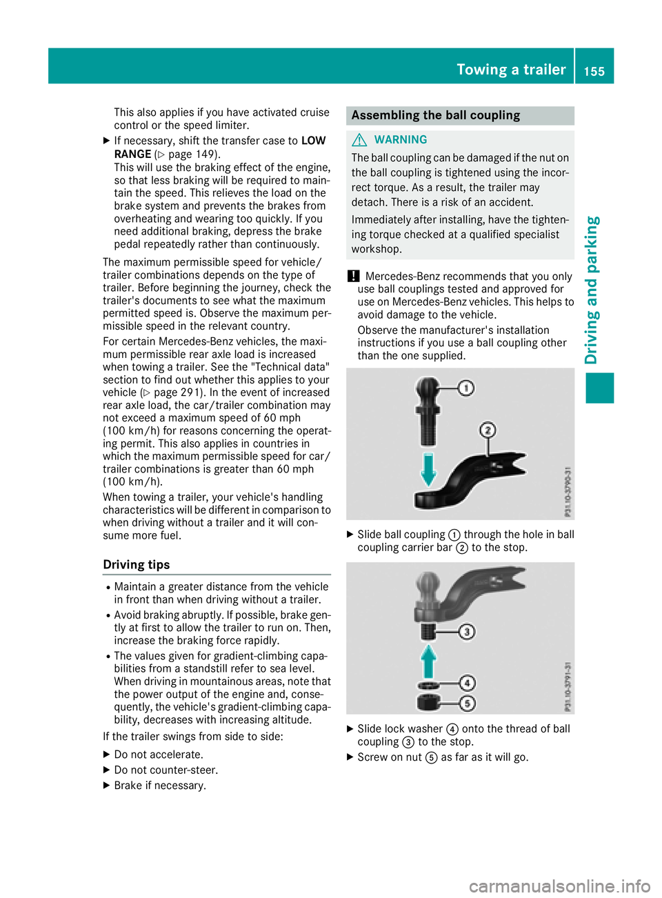
XSlide ball coupling :through the hole in ball
coupling carrier bar ;to the stop.
XSlide lock washer ?onto the thread of ball
coupling =to the stop.
XScrew on nut Aas far as it will go.
Towing a trailer155
Driving and parking
Z
Page 158 of 294
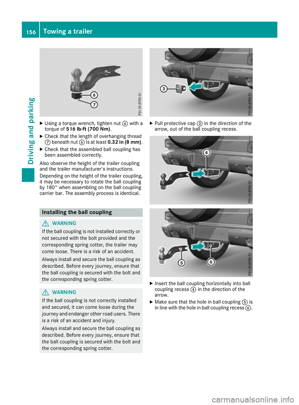
XUsing a torque wrench, tighten nutBwith a
torque of 516 lb-ft (700 Nm) .
XCheck that the length of overhanging thread
Cbeneath nut Bis at least 0.32 in (8 mm) .
XCheck that the assembled ball coupling has
been assembled correctly.
Also observe the height of the trailer coupling
and the trailer manufacturer's instructions.
Depending on the height of the trailer coupling,
it may be necessary to rotate the ball coupling
by 180° when assembling on the ball coupling
carrier bar. The assembly process is identical.
Installing the ball coupling
GWARNING
If the ball coupling is not installed correctly or not secured with the bolt provided and the
corresponding spring cotter, the trailer may
come loose. There is a risk of an accident.
Always install and secure the ball coupling as
described. Before every journey, ensure that
the ball coupling is secured with the bolt and
the corresponding spring cotter.
GWARNING
If the ball coupling is not correctly installed
and secured, it can come loose during the
journey and endanger other road users. There is a risk of an accident and injury.
Always install and secure the ball coupling as
described. Before every journey, ensure that
the ball coupling is secured with the bolt and
the corresponding spring cotter.
XPull protective cap =in the direction of the
arrow, out of the ball coupling recess.
XInsert the ball coupling horizontally into ball
coupling recess ?in the direction of the
arrow.
XMake sure that the hole in ball coupling Ais
in line with the hole in ball coupling recess B.
156Towing a trailer
Driving and parking
Page 159 of 294
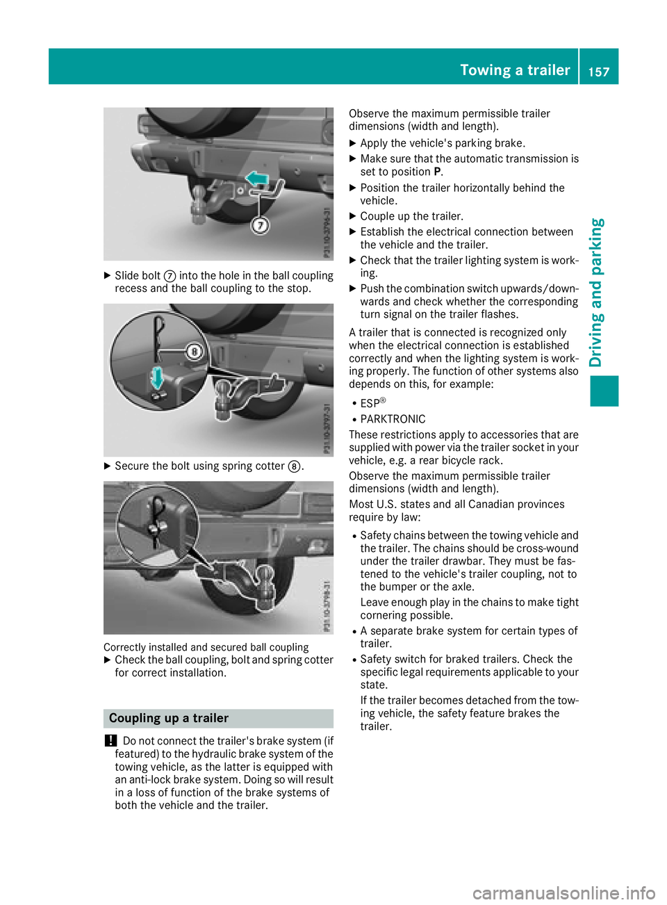
XSlide boltCinto the hole in the ball coupling
recess and the ball coupling to the stop.
XSecure the bolt using spring cotter D.
Correctly installed and secured ball couplingXCheck the ball coupling, bolt and spring cotter
for correct installation.
Coupling up a trailer
!
Do not connect the trailer's brake system (if
featured) to the hydraulic brake system of the
towing vehicle, as the latter is equipped with
an anti-lock brake system. Doing so will result
in a loss of function of the brake systems of
both the vehicle and the trailer. Observe the maximum permissible trailer
dimensions (width and length).
XApply the vehicle's parking brake.
XMake sure that the automatic transmission is
set to position
P.
XPosition the trailer horizontally behind the
vehicle.
XCouple up the trailer.
XEstablish the electrical connection between
the vehicle and the trailer.
XCheck that the trailer lighting system is work-
ing.
XPush the combination switch upwards/down-
wards and check whether the corresponding
turn signal on the trailer flashes.
A trailer that is connected is recognized only
when the electrical connection is established
correctly and when the lighting system is work-
ing properly. The function of other systems also
depends on this, for example:
RESP®
RPARKTRONIC
These restrictions apply to accessories that are
supplied with power via the trailer socket in your
vehicle, e.g. a rear bicycle rack.
Observe the maximum permissible trailer
dimensions (width and length).
Most U.S. states and all Canadian provinces
require by law
:
RSafety chains between the towing vehicle and
the trailer. The chains should be cross-wound
under the trailer drawbar. They must be fas-
tened to the vehicle's trailer coupling, not to
the bumper or the axle.
Leave enough play in the chains to make tight
cornering possible.
RA separate brake system for certain types of
trailer.
RSafety switch for braked trailers. Check the
specific legal requirements applicable to your
state.
If the trailer becomes detached from the tow-
ing vehicle, the safety feature brakes the
trailer.
Towing a trailer157
Driving and parking
Z
Page 160 of 294
Towing a trailer
There are several legal requirements for towing
a trailer, e.g. the maximum permissible speed.
Make sure that your car/trailer combination
complies with the local regulations:
Rin your place of residence
Rat your destination
The police and local authorities can provide reli- able information.
In order to accumulate driving experience and
accustom yourself to the new handling charac-
teristics, practice the following at a location
where there is no traffic:
RCornering
RStopping
RBacking up
Before driving, check the following:
RTrailer tow hitch
RSafety switch for braked trailers
RSafety chains
RElectrical connections
RLighting system
RWheels and tires
RLoad-securing measures
Adjust the exterior mirrors to provide an unob-
structed view of the rear section of the trailer.
Trailers with electronically controlled
brakes: pull away carefully in the vehicle/trailer
combination, brake manually using the brake
controller and check whether the brakes func-
tion correctly.
Check the load securing measures on a regular
basis.
When towing a trailer, your vehicle's handling
characteristics will be different in comparison
with when driving without a tra
iler.
The vehicle/trailer combination:
Ris heavier
Ris restricted in its acceleration and gradient-
climbing capability
Rhas an increased braking distance
Ris affected more by strong crosswinds
Rdemands more sensitive steering
Rhas a larger turning radius
Avoid sudden steering movements.
Avoid braking abruptly. If possible, brake gently
at first to allow the trailer to run on. Then,
increase the braking force rapidly. When overtaking, pay particular attention to the
extended length of your vehicle/trailer combi-
nation.
Due to the length of the vehicle/trailer combi-
nation, you require additional road space when
overtaking before you can change back to the
original lane.
If the automatic transmission repeatedly shifts
between gears on uphill or downhill gradients,
shift to a lower gear.
Driving in a lower gear and at a reduced speed
decreases the risk of engine damage.
Avoid constant braking. Otherwise, the vehicle
brakes and possibly also the trailer brakes may
overheat.
When driving downhill, shift to a lower gear to
utilize the engine's braking effect.
If the coolant temperature increases dramati-
cally while the air-conditioni ng s
ystem is
switched on, switch off the air-conditioning sys- tem.
Coolant heat can also be dissipated by opening
the windows and switching the ventilation
blower and the interior temperature to the high-
est level.
Decoupling a trailer
GWARNING
If you uncouple a trailer with the overrun
brake engaged, you could trap your hand
between the vehicle and the trailer drawbar.
There is a risk of injury.
Do not uncouple a trailer if the overrun brake
is engaged.
!Do not disconnect a trailer with an engaged
overrun brake. Otherwise, your vehicle could
be damaged by the rebounding of the overrun
brake.
XApply the parking brake.
XMake sure that the automatic transmission is
set to position P.
XSecure the vehicle and trailer against rolling
away.
XClose all doors, including the rear door.
XRemove the trailer cable.
XRemove the safety chains, if there are any.
XUncouple the trailer.
158Towing a trailer
Driving an d parking