torque MERCEDES-BENZ G-CLASS 2018 Owner's Manual
[x] Cancel search | Manufacturer: MERCEDES-BENZ, Model Year: 2018, Model line: G-CLASS, Model: MERCEDES-BENZ G-CLASS 2018Pages: 294, PDF Size: 4.86 MB
Page 23 of 294
Distance warning ........................... 201
DISTRONIC PLUS ........................... 201
ESP
®.............................................. 196
ESP®OFF ....................................... 197
Fuel tank ........................................ 199
General notes ................................ 191
Overview .......................................... 32
Parking brake ................................ 194
PASSENGER AIR BAG OFF ............... 39
Reserve fuel ................................... 199
Restraint system ............................ 198
Seat belt ........................................ 192
Tire pressure monitor .................... 202
Warning triangle ................................ 243
Warranty .............................................. 24
Washer fluid
Display message ............................ 191
Weather display (COMAND)
see also Digital Operator's Man-
ual .................................................. 203
Wheel and tire combinations
Tires ............................................... 279
Wheel bolt tightening torque ........... 278
Wheels
Changing a wheel .......................... 275
Checking ........................................ 257
Cleaning ......................................... 238
Important safety notes .................. 257
Information on driving .................... 257
Interchanging/changing ................ 275
Mounting a new wheel ................... 278
Mounting a wheel .......................... 276
Removing a wheel .......................... 278
Snow chains .................................. 259
Storing ........................................... 276
Tightening torque ........................... 278
Wheel size/tire size ....................... 279
Window curtain air bag
Display message ............................ 178
Operation ......................................... 46
Windows
see Side windows
Windshield
Defrosting ...................................... 100
Windshield heating ........................... 101
Windshield washer fluid
see Windshield washer system Windshield washer system
Adding washer fluid ....................... 234
Notes ............................................. 287
Windshield wipers
Problem (malfunction) ..................... 95
Rear window wiper .......................... 94
Replaci ng the w
iper blades .............. 94
Switching on/off .............................. 93
Winter driving
Important safety notes .................. 258
Slippery road surfaces ................... 128
Snow chains .................................. 259
Winter operation
Overview ........................................ 258
Radiator cover ............................... 231
Summer tires ................................. 259
Winter tires
M+S tires ....................................... 259
Wiper blades
Cleaning ......................................... 239
Important safety notes .................... 94
Replacing ......................................... 94
Wooden trim (cleaning instruc-
tions) .................................................. 241
Index21
Page 61 of 294
Braking
XIf ABS intervenes:continue to depress the
brake pedal vigorously until the braking sit-
uation is over.
XTo make a full brake application: depress
the brake pedal with full force.
If ABS intervenes when braking, you will feel a
pulsing in the brake pedal.
The pulsating brake pedal can be an indication
of hazardous road conditions, and functions as a
reminder to take extra care while driving.
Off-road ABS
ESP®automatically activates the ABS system
specifically suited to off-road terrain.
At speeds below 37 mph (60 km/h), the front
wheels lock cyclically during braking. The dig-
ging-in effect achieved in the process reduces
the stopping distance on off-road terrain. This
limits steering capability.
BAS (Brake Assist System)
General information
BAS operates in emergency braking situations.
If you depress the brake pedal quickly, BAS
automatically boosts the braking force, thus
shortening the stopping distance.
Important safety notes
iObserve the "Important safety notes" sec-
tion (Ypage 58).
GWARNING
If BAS is malfunctioning, the braking distance
in an emergency braking situation is
increased. There is a risk of an accident.
In an emergency braking situation, depress
the brake pedal with full force. ABS prevents
the wheels from locking.
Braking
XKeep the brake pedal firmly depressed until
the emergency braking situation is over.
ABS prevents the wheels from locking. The brakes will function as usual once you
release the brake pedal. BAS is deactivated.
ESP®(Electronic Stability Program)
General notes
iObserve the "Important safety notes" sec-
tion (Ypage 58).
ESP
®monitors driving stability and traction, i.e.
power transmission between the tires and the
road surface.
If ESP
®detects that the vehicle is deviating from
the direction desired by the driver, one or more
wheels are braked to stabilize the vehicle. The
engine output is also modified to keep the vehi-
cle on the desired course within physical limits.
ESP
®assists the driver when pulling away on
wet or slippery roads. ESP®can also stabilize
the vehicle during braking.
4ETS (Electronic Traction System)
iObserve the "Important safety notes" sec-
tion (Ypage 58).
4ETS traction control is part of ESP
®.
Traction control brakes the drive wheels indi-
vidually if they spin. This enables you to pull
away and accelerate on slippery surfaces, for
example if the road surface is slippery on one
side. In addition, more drive torque is transfer-
red to the wheel or wheels with traction.
Traction control remains active, even if you
deactivate ESP
®.
Important safety notes
iObserve the "Important safety notes" sec-
tion (Ypage 58).
GWARNING
If ESP
®is malfunctioning, ESP®is unable to
stabilize the vehicle. Additionally, further driv-
ing safety systems are deactivated. This
increases the risk of skidding and an accident.
Drive on carefully. Have ESP
®checked at a
qualified specialist workshop.
Driving safety systems59
Safety
Z
Page 63 of 294
XTo deactivate:press button:.
The å ESP®OFF warning lamp in the
instrument cluster lights up.
XTo activate: press button :.
The å ESP®OFF warning lamp in the
instrument cluster goes out.
Characteristics when ESP®is deactivated
If ESP®is deactivated and one or more wheels
start to spin, the ÷ESP®warning lamp in the
instrument cluster flashes. In such situations,
ESP
®will not stabilize the vehicle.
If you deactivate ESP®:
RESP®no longer improves driving stability.
REngine torque is no longer limited and the
drive wheels are able to spin.
RTraction control is still activated.
RESP®still provides support when you brake
firmly.
RMercedes-AMG vehicles: and are driving a
speed at above 62 mph (100 km/h), ESP®still
intervenes when one wheel reaches its grip
limit even though it is deactivated.
RAll other models: and are driving at a speed
above 37 mph (60 km/h), ESP®still inter-
venes when one wheel reaches its grip limit
even though it is deactivated.
Mercedes-AMG vehicles: if ESP
®is deactiva-
ted, it is reactivated automatically if you are
driving at a speed above 62 mph (100 km/h) or
you exceed a certain lateral acceleration.
All other models: if ESP
®is deactivated, it is
re
activated automatically if you are driving at a
speed above 37 mph (60 km/h) or you exceed a
certain lateral acceleration.
Trailer stabilization
General information
If your vehicle/trailer combination begins to
swerve, ESP®assists you in this situation. ESP®
slows the vehicle down by braking and limiting
the engine output until the vehicle/trailer com-
bination has stabilized.
Important safety notes
GWARNING
If road and weather conditions are poor,
trailer stabilization will not be able to prevent
the vehicle/trailer combination from swerv-
ing. Trailers with a high center of gravity can
tip over before ESP
®can detect this. There is
a risk of an accident.
Always adapt your driving style to the prevail-
ing road and weather conditions.
If your vehicle with trailer (vehicle/trailer com-
bination) begins to lurch, you can only stabilize
the vehicle/trailer combination by depressing
the brake firmly.
ESP
®trailer stabilization is active above speeds
of approximately 37 mph (60 km/h).
ESP
®trailer stabilization does not work if ESP®
is deactivated or malfunctioning.
EBD (electronic brake force distribu-
tion)
General information
EBD monitors and controls the brake pressure
on the rear wheels to improve driving stability
while braking.
Important safety notes
iObserve the "Important safety notes" sec-
tion (Ypage 58).
GWARNING
If EBD is malfunctioning, the rear wheels can
lock, e.g. under full braking. This increases the
risk of skidding and an accident.
You should therefore adapt your driving style
to the different handling characteristics. Have
the brake system checked at a qualified spe-
cialist workshop.
Observe information regarding indicator and
warning lamps (
Ypage 194) as well as display
messages (Ypage 176).
ADAPTIVE BRAKE
ADAPTIVE BRAKE provides increased braking
safety. In addition to the braking function,
ADAPTIVE BRAKE also has the HOLD function
(
Ypage 142) and hill start assist (Ypage 107).
Driving safety systems61
Safety
Z
Page 153 of 294
Differential locks
General notes
GWARNING
Whe nth edifferential locks are engaged, ABS,
4ETS ,ES P
®and BA Sare deactivated. As a
result ,th ewheels could loc kwhen braking
and th ebraking distanc eis increased. There is
a ris kof an accident.
Disengage th edifferential locks immediately
on fir msurfaces wit hgoo dgrip.
!In order to avoid damage to th etransfe r
case, you mus toperat eth evehicle on adyna-
mometer (1-axl edynamometer) only if:
Rth eaxl eno tdriven on is jacked up
or
Rth ecorrespondin gpropeller shaft is dis -
connecte dand th etransfe rcas edifferen -
tial loc kis engaged.
Differential locks improve th etraction of th e
vehicle.
Your vehicle is equipped wit h adifferential loc k
eac hfor:
Rth etransfe rcase: this controls th ebalance
between th efron tand rea raxles.
Rth erea raxle: this controls th ebalance
between th ewheels on th erea raxle.
Rth efron taxle: this controls th ebalance
between th ewheels on th efron taxle.
Information on differential gea rsyste m
an ddifferential lock
Whe nth evehicle drives around acurve, th e
wheels on th eoutsid eof th ecurve mus tcover a
greater distance. Therefore, th ewheels turn
more rapidly than on th einside. The differential,
a gear syste min th edrive train ,allow sfo rdif -
ferin grotational speeds and facilitates corner-
ing.
The disadvantage of adifferential is that th e
wheels that hav eth eleas tgrip, get th emost
drive. Fo rexample, awhee lon adrive axl elies
on snow-covered groun dand therefore has no
traction .The differential sends most of th edrive
forc eto this whee lbecause th eforc etake sth e
rout eof th elowest resistance. The opposite
whee lon this axle, however, whic hstand son
fir m groun dand could therefore allow propul- sion, receives no drivin
gpower. 4ETS compen-
sates fo rthis disadvantage. 4ETS provides goo d
steerability by automatically braking th espin-
ning wheel. 4ETS provides th ewhee lon th efir m
surfac ewit hmore drive force, whic hin turn pro -
vides propulsion .
ES P
®and 4ETS are traction systems that are
idea lfo rroad drivin gand suitable fo rligh toff-
road driving. The LOW RANGEoff-road g
ear
also improves off-road capability.
Mor echallengin goff-road condition srequire
additional measures suc has locking on eor
more differential.
Your vehicle is equipped wit hthree differential
locks :
Rforth etransfe rcas e
Rforth efron taxl e
Rforth erea raxl e
Each differential loc kcan be engage dwit hth e
correspondin gswitch on th ecenter console. If
th edifferential in th etransfe rcas eis locked, th e
fron tand rea rwheels rotate at th esam espeed.
If th edifferential fo rth erea raxl eis locked, bot h
rea rwheels rotate at th esam espeed, regard -
les sof their respective torque. Note, engaging
th edifferential loc kgreatly impairs th evehicle' s
steerability.
Note, it is imperative to use th edifferential func-
tion when drivin gon fir mroad surfaces. Under
no circumstances should th edifferential be
locke dwhen drivin gon fir mroad surfaces. Oth-
erwise ,th evehicle may no tbe steerable and you
could los econtro lof th evehicle. Therefore, only
engage th edifferential loc kwhen drivin goff-
road. You should only engage th edifferential
loc kif act ivati
n
g4ETS and ES P®drivingsystems
and LOW RANGE off-road gear prove to be
insufficient.
Engaging th edifferential lock s
General notes
The switches are located on th ecenter console.
Off-road driving systems15 1
Driving an d parking
Z
Page 157 of 294
This also applies if you have activated cruise
control or the speed limiter.
XIf necessary, shift the transfer case toLOW
RANGE (Ypage 149).
This will use the braking effect of the engine,
so that less braking will be required to main-
tain the speed. This relieves the load on the
brake system and prevents the brakes from
overheating and wearing too quickly. If you
need additional braking, depress the brake
pedal repeatedly rather than continuously.
The maximum permissible speed for vehicle/
trailer combinations depends on the type of
trailer. Before beginning the journey, check the
trailer's documents to see what the maximum
permitted speed is. Observe the maximum per-
missible speed in the relevant country.
For certain Mercedes-Benz vehicles, the maxi-
mum permissible rear axle load is increased
when towing a trailer. See the "Technical data"
section to find out whether this applies to your
vehicle (
Ypage 291). In the event of increased
rear axle load, the car/trailer combination may
not exceed a maximum speed of 60 mph
(100 km/h) for reasons concerning the operat-
ing permit. This also applies in countries in
which the maximum permissible speed for car/ trailer combinations is greater than 60 mph
(100 km/h).
When towing a trailer, your vehicle's handling
characteristics will be different in comparison to
when driving without a trailer and it will con-
sume more fuel.
Driving tips
RMaintain a greater distance from the vehicle
in front than when driving without a trailer.
RAvoid braking abruptly. If possible, brake gen-tly at first to allow the trailer to run on. Then,
increase the braking force rapidly.
RThe values given for gradient-climbing capa-
bilities from a standstill refer to sea level.
When driving in mountainous areas, note that
the power output of the engine and, conse-
quently, the vehicle's gradient-climbing capa-
bility, decreases with increasing altitude.
If the trailer swings from side to side:
XDo not accelerate.
XDo not counter-steer.
XBrake if necessary.
Assembling the ball coupling
GWARNING
The ball coupling can be damaged if the nut on
the ball coupling is tightened using the incor-
rect torque. As a result, the trailer may
detach. There is a risk of an accident.
Immediately after installing, have the tighten-
ing torque checked at a qualified specialist
workshop.
!Mercedes-Benz recommends that you only
use ball couplings tested and approved for
use on Mercedes-Benz vehicles. This helps to avoid damage to the vehicle.
Observe the manufacturer's installation
instructions if you use a ball coupling other
than the one supplied.
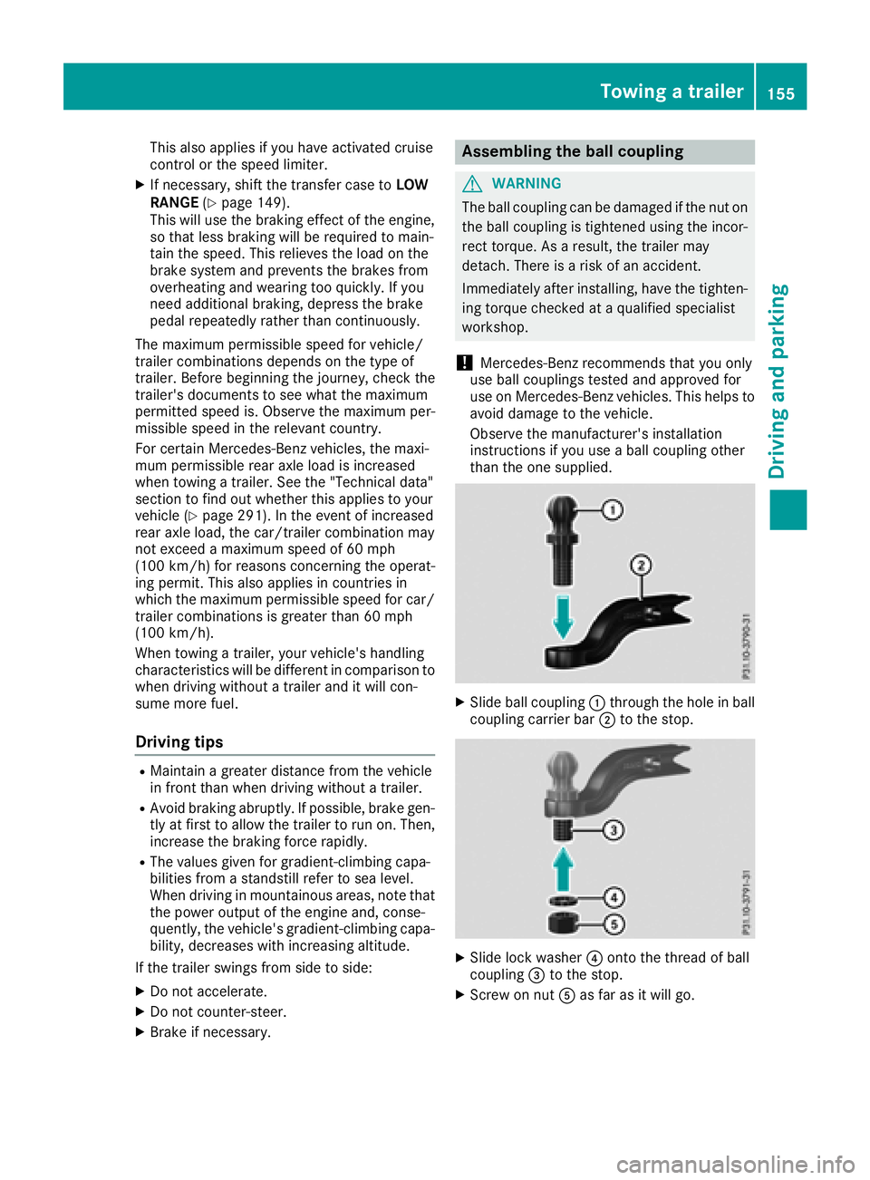
XSlide ball coupling :through the hole in ball
coupling carrier bar ;to the stop.
XSlide lock washer ?onto the thread of ball
coupling =to the stop.
XScrew on nut Aas far as it will go.
Towing a trailer155
Driving and parking
Z
Page 158 of 294
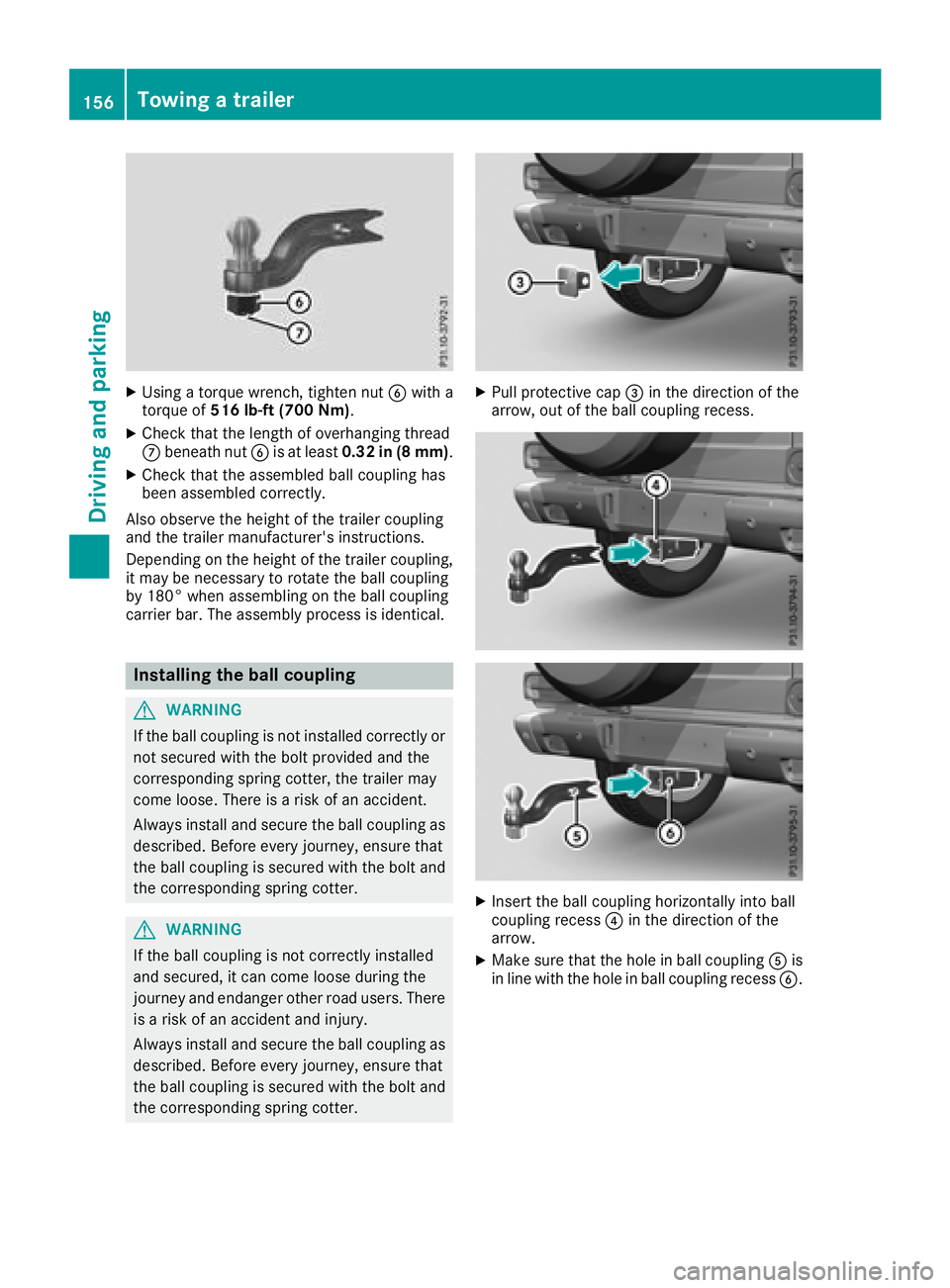
XUsing a torque wrench, tighten nutBwith a
torque of 516 lb-ft (700 Nm) .
XCheck that the length of overhanging thread
Cbeneath nut Bis at least 0.32 in (8 mm) .
XCheck that the assembled ball coupling has
been assembled correctly.
Also observe the height of the trailer coupling
and the trailer manufacturer's instructions.
Depending on the height of the trailer coupling,
it may be necessary to rotate the ball coupling
by 180° when assembling on the ball coupling
carrier bar. The assembly process is identical.
Installing the ball coupling
GWARNING
If the ball coupling is not installed correctly or not secured with the bolt provided and the
corresponding spring cotter, the trailer may
come loose. There is a risk of an accident.
Always install and secure the ball coupling as
described. Before every journey, ensure that
the ball coupling is secured with the bolt and
the corresponding spring cotter.
GWARNING
If the ball coupling is not correctly installed
and secured, it can come loose during the
journey and endanger other road users. There is a risk of an accident and injury.
Always install and secure the ball coupling as
described. Before every journey, ensure that
the ball coupling is secured with the bolt and
the corresponding spring cotter.
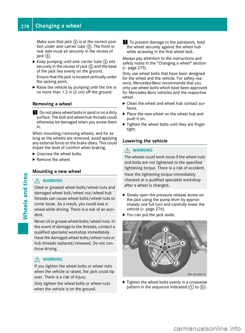
XPull protective cap =in the direction of the
arrow, out of the ball coupling recess.
XInsert the ball coupling horizontally into ball
coupling recess ?in the direction of the
arrow.
XMake sure that the hole in ball coupling Ais
in line with the hole in ball coupling recess B.
156Towing a trailer
Driving and parking
Page 280 of 294
Make sure that jackAis at the correct posi-
tion under axle carrier tube ?. The front or
rear axle must sit securely in the recess of
jack A.
XKeep pumping until axle carrier tube ?sits
securely in the recess of jack Aand the base
of the jack lies evenly on the ground.
Ensure that the jack is located vertically under
the jacking point.
XRaise the vehicle by pumping until the tire is
no more than 1.2 in (3 cm) off the ground.
Removing a wheel
!Do not place wheel bolts in sand or on a dirty
surface. The bolt and wheel hub threads could
otherwise be damaged when you screw them
in.
When mounting/removing wheels, and for as
long as the wheels are removed, avoid applying
any external force on the brake disks. This could impair the level of comfort when braking.
XUnscrew the wheel bolts.
XRemove the wheel.
Mounting a new wheel
GWARNING
Oiled or greased wheel bolts/wheel nuts and
damaged wheel bolt/wheel nut/wheel hub
threads can cause wheel bolts/wheel nuts to
come loose. As a result, you could lose a
wheel while driving. There is a risk of an acci-
dent.
Never oil or grease wheel bolts/wheel nuts. In
the event of damage to the threads, contact a
qualified specialist workshop immediately.
Have the damaged wheel bolts/wheel nuts or
hub threads replaced/renewed. Do not con-
tinue driving.
GWARNING
If you tighten the wheel bolts or wheel nuts
when the vehicle is raised, the jack could tip
over. There is a risk of injury.
Only tighten the wheel bolts or wheel nuts
when the vehicle is on the ground.
!To prevent damage to the paintwork, hold
the wheel securely against the wheel hub
while screwing in the first wheel bolt.
Always pay attention to the instructions and
safety notes in the "Changing a wheel" section
(
Ypage 275).
Only use wheel bolts that have been designed
for the wheel and the vehicle. For safety rea-
sons, Mercedes-Benz recommends that you
only use wheel bolts which have been approved
for Mercedes-Benz vehicles and the respective
wheel.
XClean the wheel and wheel hub contact sur-
faces.
XPlace the new wheel on the wheel hub and
push it on.
XTighten the wheel bolts until they are finger-
tight.
Lowering the vehicle
GWARNING
The wheels could work loose if the wheel nuts and bolts are not tightened to the specified
tightening torque. There is a risk of accident.
Have the tightening torque immediately
checked at a qualified specialist workshop
after a wheel is changed.
XSlowly open the pressure release screw on
the jack using the pump lever by approx-
imately one full turn and carefully lower the
vehicle (
Ypage 276).
XYou can put the jack aside.
XTighten the wheel bolts evenly in a crosswisepattern in the sequence indicated (: toA).
278Changing a wheel
Wheels and tires
Page 281 of 294
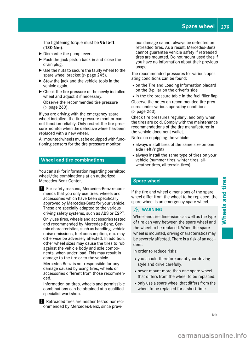
The tightening torque must be96 lb-ft
(130 Nm).
XDismantle the pump lever.
XPush the jack piston back in and close the
drain plug.
XUse the nuts to secure the faulty wheel to the
spare wheel bracket (Ypage 245).
XStow the jack and the vehicle tools in the
vehicle again.
XCheck the tire pressure of the newly installed
wheel and adjust it if necessary.
Observe the recommended tire pressure
(
Ypage 260).
If you are driving with the emergency spare
wheel installed, the tire pressure monitor can-
not function reliably. Only restart the tire pres-
sure monitor when the defective wheel has been replaced with a new wheel.
All mounted wheels must be equipped with func-
tioning sensors for the tire pressure monitor.
Wheel and tire combinations
You can ask for information regarding permittedwheel/tire combinations at an authorized
Mercedes-Benz Center.
!For safety reasons, Mercedes-Benz recom-
mends that you only use tires, wheels and
accessories which have been specifically
approved by Mercedes-Benz for your vehicle.
These are specially adapted to the various
driving safety systems, such as ABS or ESP
®.
Only use tires, wheels and accessories tested
and recommended by Mercedes-Benz. Cer-
tain characteristics, such as handling, vehicle
noise emissions, fuel consumption, etc. may
otherwise be adversely affected. In addition,
other wheel sizes may cause the tires to rub
against the vehicle body and axle compo-
nents, when under load. This may result in
damage to the tire or to the vehicle.
Mercedes-Benz is not responsible for any
damage caused by using tires, wheels or
accessories different from those recommen-
ded.
Information on tires, wheels and permissible
combinations can be obtained at a qualified
specialist workshop.
!Retreaded tires are neither tested nor rec-
ommended by Mercedes-Benz, since previ- ous damage cannot always be detected on
retreaded tires. As a result, Mercedes-Benz
cannot guarantee vehicle safety if retreaded
tires are mounted. Do not mount used tires if
you have no information about their previous
usage.
The recommended pressures for various oper-
ating conditions can be found:
Ron the Tire and Loading Information placard
on the B-pillar on the driver's side
Rin the tire pressure table in the fuel filler flap
Observe the notes on recommended tire pres-
sures under various operating conditions
(
Ypage 260).
Check tire pressures regularly, and only when
the tires are cold. Comply with the maintenance
recommendations of the tire manufacturer in
the vehicle document wallet.
Notes on equipping the vehicle:
Ralways install tires of the same size on one
axle (left/right)
Ralways install the same type of tires on your
vehicle (summer tires, winter tires, all-
weather tires, all-terrain tires)
Spare wheel
If the tire and wheel dimensions of the spare
wheel differ from the wheel to be replaced, the
spare wheel is an emergency spare wheel.
GWARNING
Wheel and tire dimensions as well as the type of tire can vary between the spare wheel and
the wheel to be replaced. When the spare
wheel is mounted, driving characteristics may be severely affected. There is a risk of an acci-
dent.
In order to reduce risks:
Ryou should therefore adapt your driving
style and drive carefully.
Rnever mount more than one spare wheel
that differs from the wheel to be replaced.
Ronly use a spare wheel that differs from the
wheel to be replaced for a short time.
Spare wheel279
Wheels and tires
Z
Page 293 of 294
which corresponds to an approach/departure
angle of 45°.
Accelerate carefully and make sure that the
wheels do not spin when driving on steep ter-
rain.
iIf the load on the front axle is reduced when
pulling away on a steep uphill slope, the front
wheels have a tendency to spin. 4ETS detects
this and brakes the wheels accordingly. The
rear wheel torque is increased, making it eas-
ier to drive off.
For further information about the maximum gra-
dient climbing ability, see (
Ypage 132).
Trailer tow hitch
Permissible trailer load, braked (at a
minimum gradient-climbing capabil-
ity of 12% from a standstill)
Missing values were not available at time of
going to print.
Model
Mercedes-AMG
G 65
All other models7716 lbs (3500 kg)
Maximum drawbar noseweight
!
Use a drawbar noseweight as close as pos-
sible to the maximum permissible nose-
weight. Do not use a noseweight of less than
50 kg, otherwise the trailer may come loose.
Note that the payload and the rear axle load
are reduced by the actual payload.
The drawbar load reduces the permissible over-
all load and rear axle load.
The drawbar load acts from above onto the ball
head on the trailer tow hitch.
The drawbar noseweight is not included in the
trailer load. Missing values were not available at time of
going to print.
ModelPermissible nose-
weight
Mercedes-AMG
G 65
All other models308.6 lbs (140kg )
The actual noseweight may not be higher than
the value which is given. The value can be found
on the trailer tow hitch or trailer identification
plates. The lowest weight applies.
The maximum permissible trailer drawbar nose-
weight is the maximum weight with which the
trailer drawbar can be loaded. The permissible
trailer drawbar noseweight is the limit for
Mercedes-Benz-approved trailer couplings.
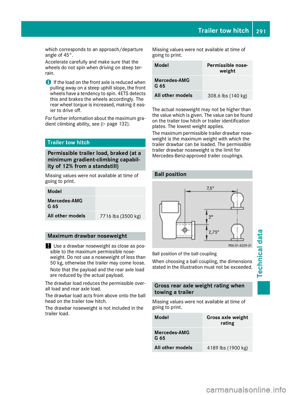
Ball position
Ball position of the ball coupling
When choosing a ball coupling, the dimensions
stated in the illustration must not be exceeded.
Gross rear axle weight rating when
towing a trailer
Missing values were not available at time of
going to print.
ModelGross axle weight rating
Mercedes-AMG
G 65
All other models4189 lbs (1900 kg)
Trailer tow hitch291
Technical data
Z