tow MERCEDES-BENZ G-CLASS SUV 2012 Service Manual
[x] Cancel search | Manufacturer: MERCEDES-BENZ, Model Year: 2012, Model line: G-CLASS SUV, Model: MERCEDES-BENZ G-CLASS SUV 2012Pages: 357, PDF Size: 8.86 MB
Page 202 of 357
Warning displays
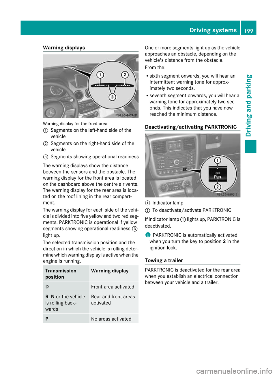
Warning display for the front area
:
Segments on the left-hand side of the
vehicle
; Segments on the right-hand side of the
vehicle
= Segments showing operational readiness
The warning displays show the distance
between the sensors and the obstacle. The
warning display for the front area is located
on the dashboard above the centre airv ents.
The warning display for the rear area is loca-
ted on the roof lining in the rear compart-
ment.
The warning display for each side of the vehi-
cle is divided into five yellow and two red seg-
ments. PARKTRONIC is operational if yellow
segments showing operational readiness =
light up.
The selected transmission position and the
direction in which the vehicle is rolling deter-
mine which warning display is active when the
engine is running. Transmission
position Warning display
D
Front area activated
R,
Nor the vehicle
is rolling back-
wards Rear and front areas
activated
P
No areas activated One or more segments light up as the vehicle
approaches an obstacle, depending on the
vehicle's distance from the obstacle.
From the:
R
sixth segmen tonwards, you will hea ran
intermittent warning ton efor approx-
imately two seconds.
R seventh segment onwards, you will hear a
warning tone for approximately two sec-
onds. This indicates that you have now
reached the minimum distance.
Deactivating/activating PARKTRONIC :
Indicator lamp
; To deactivate/activate PARKTRONIC
If indicator lamp :lights up, PARKTRONIC is
deactivated.
i PARKTRONIC is automatically activated
when you turn the key to position 2in the
ignition lock.
Towing atrailer PARKTRONIC is deactivated for the rea
rarea
when you establish an electrical connection
between yourv ehicle and a trailer. Driving systems
199Driving and parking Z
Page 205 of 357
HIGH
RANGE
Position for all normal on-
road driving conditions
LOW
RANGE
Low-range position for driv-
ing off-road
Also for use on steep uphill
or downhill gradients, espe-
cially when towing a trailer
The vehicle travels around
halft
he speed of on-road
driving range HIGH RANGE.
The tractive power is corre-
spondingly higher. Shifting the transfer case
Important safety notes
G
WARNING
When the transfer case is in the neutral posi-
tion, power transmission to the driven wheels
is interrupted. As a result, the vehicle could
roll away.T here is a risk of an accident.
Secure the vehicle with the parking brake, and
on uphill or downhill gradients, also secure it
with a device such as a wheel chock. G
WARNING
When the transfer case is in the neutral posi-
tion, power transmission to the driven wheels
is interrupted. As a result, the vehicle could
roll away.T here is a risk of an accident.
Secure the vehicle with the parking brake, and
on uphill or downhill gradients, also secure it
with a device such as a wheel chock.
Always wait for the gear change process from
HIGH RANGE toLOW RANGE and from
LOW RANGE toHIGH RANGE to complete.
Do not turn off the engine while changing gear
and do not shift the automatic transmission
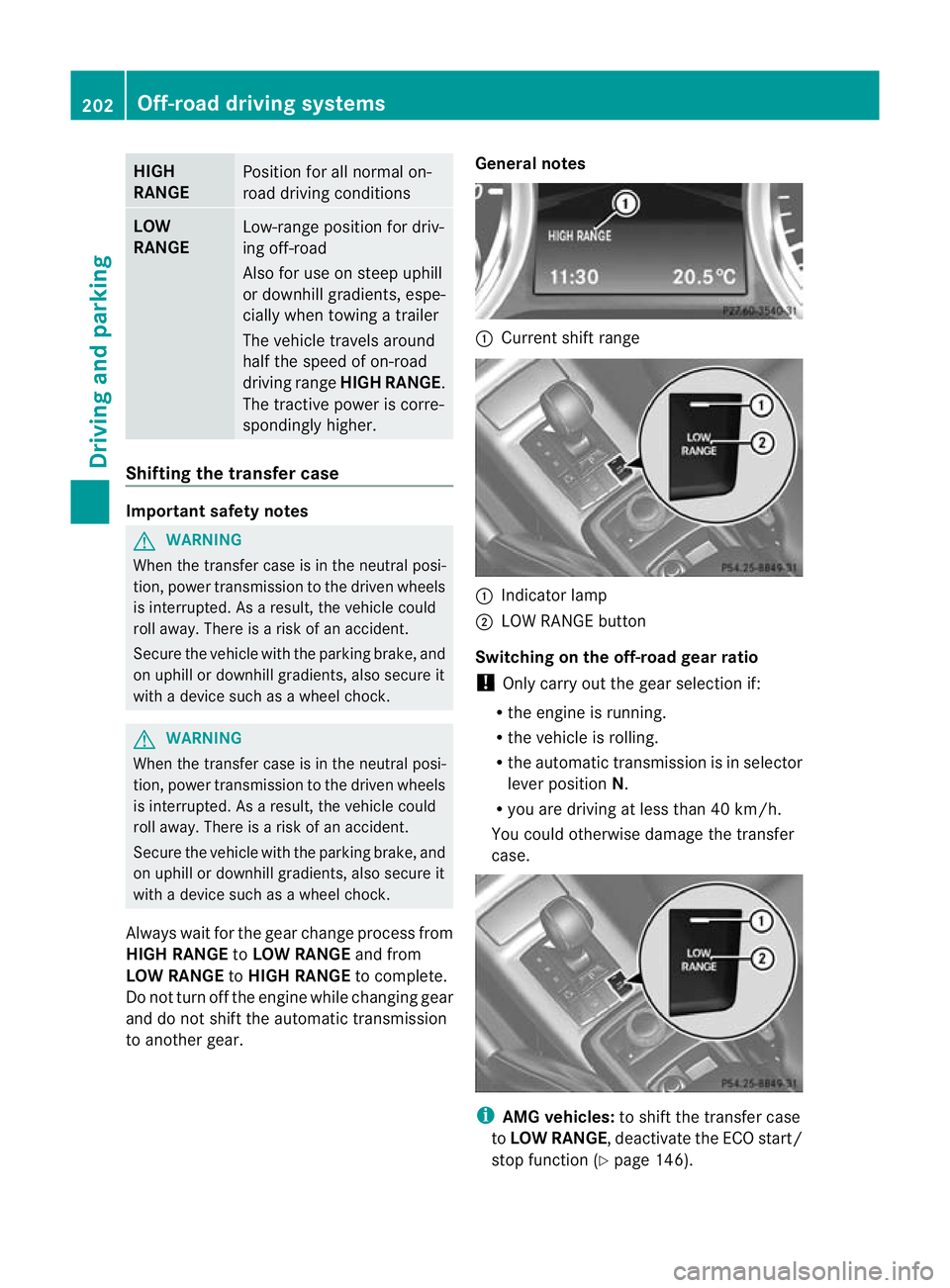
to another gear. General notes :
Current shift range :
Indicator lamp
; LOW RANGE button
Switching on the off-road gear ratio
! Only carry out the gear selection if:
R the engine is running.
R the vehicle is rolling.
R the automatic transmission is in selector
lever position N.
R you are driving at less than 40 km/h.
You could otherwise damage the transfer
case. i
AMG vehicles: to shift the transfer case
to LOW RANGE, deactivate the ECO start/
stop function (Y page 146).202
Off-road driving systemsDriving and parking
Page 209 of 357
Towing
atrailer Notes on towing
atrailer
Important safety notes G
WARNING
The braking syste mcan overheat if you leave
your foo tonthe brake pedal while driving.
This increases the braking distance and could
even cause the braking system to fail. There
is a risk of an accident.
Never use the brake pedal as a footrest.Do
not simultaneously depress both the brake
pedal and the accelerato rpedal while driving. G
WARNING
You could lose control of the vehicle/trailer
combination if it begins to swerve. The vehi-
cle/trailer combination could even overturn.
There is a risk of an accident.
On no account should you attempt to
straighten out the vehicle/trailer combina-
tion by increasing speed. Decrease your
speed and do not countersteer. Brake if nec-
essary. G
WARNING
If the ball coupling has not been correctly fit-
ted and has not been secured with the bolt
supplied and the correspondin gspring cotter,
the trailer can detach. There is a risk of an
accident.
Always fit and secure the ball coupling as
described. Before beginning each journey,
make sure that the fitted ball coupling is
secured with the bolt supplied and the corre-
sponding spring cotter.
You will find the applicable permissible val-
ues, which must not be exceeded, in the vehi-
cle documents. You will find the values
approved by the manufacturer on the vehicle
identification plates and those for the towing
vehicle in the "Technical data" section
(Y page 340). Couple and uncouple the trailer carefully. If
you do not couple the trailer to the towing
vehicle correctly, the trailer could become
detached.
Make sure that the following values are not
exceeded:
R the permissible trailer drawbar noseweight
R the permissible trailer load
R the permissible rear axle load of the towing
vehicle
R the maximum permissible gross vehicle
weight of both the towing vehicle and the
trailer
When towing a trailer, your vehicle's handling
characteristics will be differen tincomparison
to when driving without a trailer.
The vehicle/trailer combination:
R is heavier
R is restricted in its acceleration and gradi-
ent-climbing capability
R has an increased braking distance
R is affected more by strong crosswinds
R demands more sensitive steering
R has a larger turning circle
This can impair the vehicle's handling char-
acteristics.
When towing a trailer, always adjust your
speed to the current road and weather con-
ditions. Do not exceed the maximum permis-
sible speed for your vehicle/trailer combina-
tion.
General notes !
Use a drawbar noseweight as close to the
maximum permissible noseweight as pos-
sible. Do not use a noseweight of less than
80 kg; otherwise, the trailer may come
loose.
Note that the payload and the rear axle load
are reduced by the actual payload.
i When towing a trailer, set the tyre pres-
sure on the rear axle of the towing vehicle 206
Towing
atrailerDriving an d parking
Page 210 of 357
for a maximu
mload; see the tyre pressure
table in the fuel filler flap (Y page 325).
You will find installation dimensions and loads
in the technical data (Y page 350).
The maximum permissible trailer drawbar
noseweight on the ball coupling is:
R 140 kg (G-Class long-wheelbase version)
R 115 kg (G-Class Cabriolet)
However, the actual noseweight must not
exceed the value given on the trailer tow hitch
or trailer identification plates. The lowest
weight applies.
i When towing a trailer, set the tyre pres-
sure on the rear axle of the towing vehicle
for a maximum load; see the tyre pressure
table in the fuel filler flap (Y page 325).
Please note that when towing a trailer, PARK-
TRONIC (Y page 197) and Blind Spot Assist
(Y page 190) are only available with limita-
tions, or not at all.
i On vehicles without level control, the
height of the ball coupling will alter accord-
ing to the load placed on the vehicle. If nec-
essary, use a trailer with a height-adjusta-
ble drawbar.
Driving tips X
On long and steep downhill gradients,
select shift range 1,2or 3(Y page 153) in
good time.
i This also applies if you have activated
cruise control or SPEEDTRONIC.
X If necessary, shift the transfer case to LOW
RANGE(Y page 202).
This will use the braking effect of the
engine, so less braking will be required to
prevent the vehicle from gaining speed.
This relieves the load on the brake system
and prevents the brakes from overheating
and wearing too quickly. If you need addi-
tional braking, depress the brake pedal
repeatedly rather than continuously. The maximum permissible speed for vehicle/
trailer combinations depends on the type of
trailer. Before beginning the journey, check
the trailer's documents to see what the max-
imum permitted speed is. Observe the legally
prescribed maximum speed in the relevant
country.
For certain Mercedes-Benz vehicles, the max-
imum permissible rear axle load is increased
when towing a trailer. Refer to the "Technical
data" section to find out whether this applies
to your vehicle. If you utilise any of the added
maximum rear axle load when towing a trailer,
the vehicle/trailer combination may not
exceed a maximum speed of 100 km/h for
reasons concerning the operating permit.
This also applies in countries in which the
permissible maximum speed for vehicle/
trailer combinations is above 100 km/h.
When towing a trailer, your vehicle's handling
characteristics will be different in comparison
to when driving without a trailer, and it will
consume more fuel.
Driving tips
If the trailer swings from side to side:
X
Do not accelerate.
X Do not countersteer.
X Brake if necessary.
R Maintain a greater distance from the vehi-
cle in front than when driving without a
trailer.
R Avoid braking abruptly. If possible, brake
gently at first to allow the trailer to run on.
Then, increase the braking force rapidly.
R The values given for gradient-climbing
capabilities from a standstill refer to sea
level. When driving in mountainous areas,
note that the power output of the engine,
and consequently the vehicle's gradient-
climbing capability, decrease with increas-
ing altitude. Towing
atrailer
207Driving an d parking Z
Page 211 of 357
Trailer power supply
! You can connect accessories with a max-
imum power consumption of 180 W to the
permanent powe rsupply.
You must no tcharge a trailer battery using
the power supply.
The trailer socket of your vehicle is equipped
at the factory with apermanen tpower supply.
The permanent power supply is supplied via
trailer socket pin 9.
You can find more information about fitting
the trailer electrics at a qualified specialist
workshop. Trailer with 7-pin connector
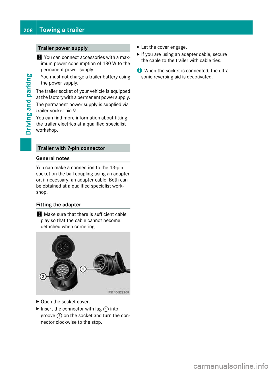
General notes You can make a connection to the 13-pin
socket on the ball coupling using an adapter
or, if necessary, an adapter cable. Both can
be obtained at a qualified specialist work-
shop.
Fitting the adapter !
Make sure that there is sufficient cable
play so that the cable cannot become
detached when cornering. X
Open the socket cover.
X Insert the connector with lug :into
groove ;on the socket and turn the con-
nector clockwise to the stop. X
Let the cover engage.
X If you are using an adapter cable, secure
the cable to the trailer with cable ties.
i When the socket is connected, the ultra-
sonic reversing aid is deactivated. 208
Towing
atrailerDriving an d parking
Page 246 of 357
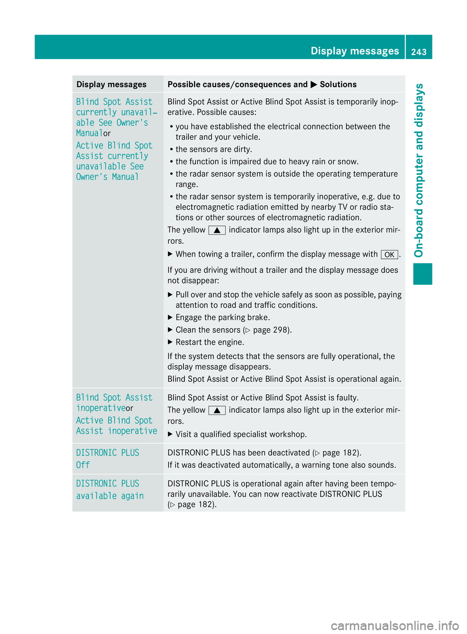
Display messages Possible causes/consequences and
M Solutions
Blind Spot Assist
currently unavail‐
able See Owner's
Manual or
Active Blind Spot Assist currently
unavailable See
Owner's Manual Blind Spot Assis
torActive Blind Spot Assist is temporarily inop-
erative .Possible causes:
R you have established the electrical connection between the
trailer and your vehicle.
R the sensors are dirty.
R the function is impaired due to heavy rain or snow.
R the radar sensor system is outside the operating temperature
range.
R the radar sensor system is temporarily inoperative, e.g. due to
electromagnetic radiation emitted by nearby TV or radio sta-
tions or other sources of electromagnetic radiation.
The yellow 9indicator lamps also light up in the exterior mir-
rors.
X When towing a trailer, confirm the display message with a.
If you are driving without a trailer and the display message does
not disappear:
X Pull over and stop the vehicle safely as soon as possible, paying
attention to road and traffic conditions.
X Engage the parking brake.
X Clean the sensors (Y page 298).
X Restart the engine.
If the system detects that the sensors are fully operational, the
display message disappears.
Blind Spot Assist or Active Blind Spot Assist is operational again. Blind Spot Assist
inoperative or
Active Blind Spot Assist inoperative Blind Spot Assist or Active Blind Spot Assist is faulty.
The yellow 9indicator lamps also light up in the exterior mir-
rors.
X Visit a qualified specialist workshop. DISTRONIC PLUS
Off DISTRONIC PLUS has been deactivated (Y
page 182).
If it was deactivated automatically, a warning tone also sounds. DISTRONIC PLUS
available again DISTRONIC PLUS is operational again after having been tempo-
rarily unavailable. You can now reactivate DISTRONIC PLUS
(Y page 182). Display messages
243On-board computer and displays Z
Page 255 of 357
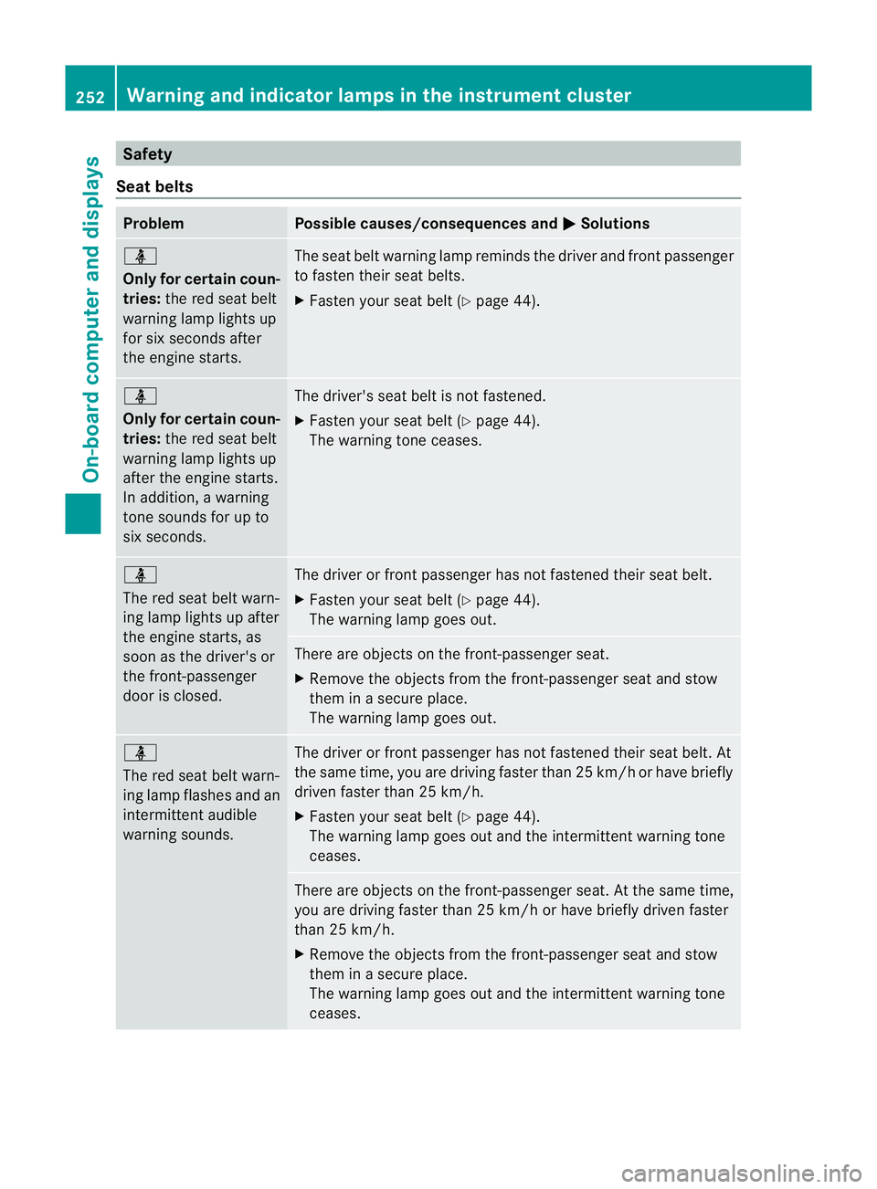
Safety
Seat belts Problem Possible causes/consequences and
M Solutions
ü
Only for certain coun-
tries:
the red seat belt
warning lamp lights up
for six seconds after
the engine starts. The seat belt warning lamp reminds the driver and front passenger
to fasten their seat belts.
X
Fasten your seat belt (Y page 44).ü
Only for certain coun-
tries:
the red seat belt
warning lamp lights up
after the engine starts.
In addition, a warning
tone sounds for up to
six seconds. The driver's seat belt is not fastened.
X
Fasten your seat belt (Y page 44).
The warning tone ceases. ü
The red seat belt warn-
ing lamp lights up after
the engine starts, as
soon as the driver's or
the front-passenger
door is closed. The driver or front passenger has not fastened their seat belt.
X
Fasten your seat belt (Y page 44).
The warning lamp goes out. There are objects on the front-passenger seat.
X
Remove the objects from the front-passenger seat and stow
them in a secure place.
The warning lamp goes out. ü
The red seat belt warn-
ing lamp flashes and an
intermittenta udible
warning sounds. The driver or fron
tpassenger has no tfastened their seat belt .At
the same time, you are driving faste rthan 25 km/h or have briefly
driven faster than 25 km/h.
X Fasten your seat belt (Y page 44).
The warning lamp goes out and the intermittent warning tone
ceases. There are objects on the front-passenger seat. At the same time,
you are driving faster than 25 km/h or have briefly driven faster
than 25 km/h.
X
Remove the objects from the front-passenger seat and stow
them in a secure place.
The warning lamp goes out and the intermittent warning tone
ceases. 252
Warning and indicator lamps in the instrument clusterOn-board computer and displays
Page 268 of 357
Useful information
............................266
Loading guidelines ............................266
Stowage areas .................................. 267
Features ............................................. 275 265Stowing and features
Page 269 of 357
Useful information
i This Owner's Manual describes all mod-
els, series and optional equipment for your
vehicle that were available at the time of
going to press. Country-specific differen-
ces are possible. Note that your vehicle
may not be fitted with all features descri-
bed. This is also the case for systems and
functions relevant to safety.
i Read the information on qualified special-
ist workshops: (Y page 22). Loading guidelines
G
WARNING
Secure and position the load as described in
the loading guidelines.
Otherwise, vehicle occupants could
be injured by the load being thrown around in
the even tofsharp braking, a sudden change
in direction or an accident. This also applies
to seats which have been removed.
You will find further information in the "Secur-
ing a load" section.
Even if you follow all the loading guidelines,
the load will increase the risk of injury in the
event of an accident. G
WARNING
Keep the boot lid/tailgate closed when the
engine is running. Otherwise, you could be
poisoned by exhaust fumes entering the vehi-
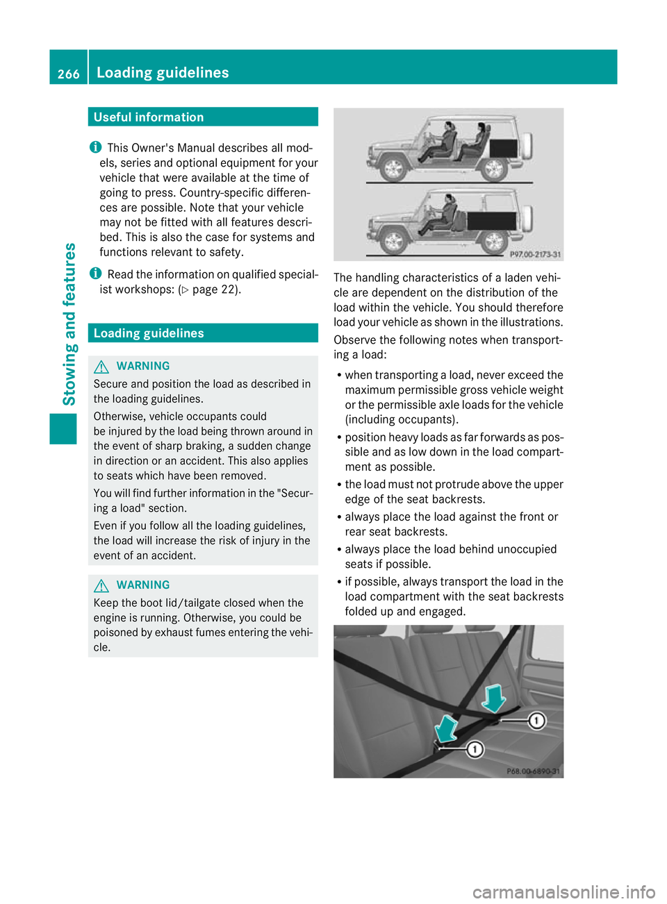
cle. The handling characteristics of a laden vehi-
cle are dependent on the distribution of the
load within the vehicle. You should therefore
load your vehicle as shown in the illustrations.
Observe the following notes when transport-
ing a load:
R when transporting a load, never exceed the
maximum permissible gross vehicle weight
or the permissible axle loads for the vehicle
(including occupants).
R position heavy loads as far forwards as pos-
sible and as low down in the load compart-
ment as possible.
R the load must not protrude above the upper
edge of the seat backrests.
R always place the load against the front or
rear seat backrests.
R always place the load behind unoccupied
seats if possible.
R if possible, always transport the load in the
load compartmentw ith the seat backrests
folded up and engaged. 266
Loading guidelinesStowing and features
Page 270 of 357
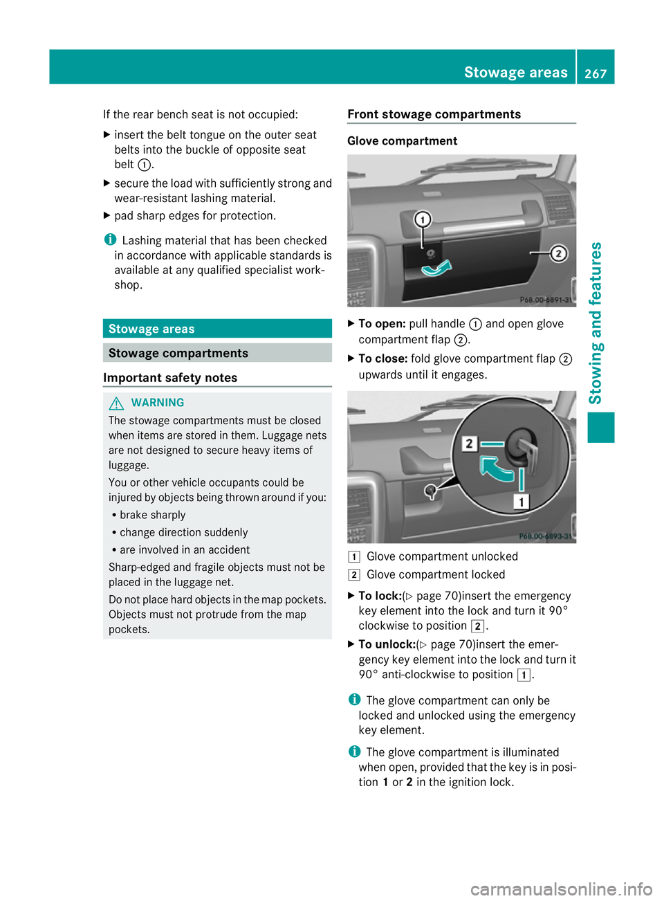
If the rear bench seat is not occupied:
X
insert the belt tongue on the outer seat
belts into the buckle of opposite seat
belt :.
X secure the load with sufficiently strong and
wear-resistant lashing material.
X pad sharp edges for protection.
i Lashing material that has been checked
in accordance with applicable standards is
available at any qualified specialist work-
shop. Stowage areas
Stowage compartments
Important safety notes G
WARNING
The stowage compartments must be closed
when items are stored in them. Luggage nets
are not designed to secure heavy items of
luggage.
You or other vehicle occupants could be
injured by objects being thrown around if you:
R brake sharply
R change direction suddenly
R are involved in an accident
Sharp-edged and fragile objects must not be
placed in the luggage net.
Do not place hard objects in the map pockets.
Objects must not protrude from the map
pockets. Front stowage compartments Glove compartment
X
To open: pull handle :and open glove
compartment flap ;.
X To close: fold glove compartment flap ;
upwards until it engages. 1
Glove compartment unlocked
2 Glove compartment locked
X To lock:(Y page 70)insert the emergency
key element into the lock and turn it 90°
clockwise to position 2.
X To unlock:(Y page 70)insert the emer-
gency key element into the lock and turn it
90° anti-clockwise to position 1.
i The glove compartment can only be
locked and unlocked using the emergency
key element.
i The glove compartment is illuminated
when open, provided that the key is in posi-
tion 1or 2in the ignition lock. Stowage areas
267Stowing and features Z