brake light MERCEDES-BENZ G500 2002 W463 Owner's Manual
[x] Cancel search | Manufacturer: MERCEDES-BENZ, Model Year: 2002, Model line: G500, Model: MERCEDES-BENZ G500 2002 W463Pages: 385, PDF Size: 30.37 MB
Page 7 of 385

4 Contents
Instrument cluster displayMalfunction and indicator
lamps in the
instrument cluster ....................264
On-board diagnostic system .........265
Check engine malfunction
indicator lamp .............................265
Brake warning lamp ..................266
Supplemental restraint system
(SRS) indicator lamp ..................267
Fuel reserve warning .................268
ABS malfunction
indicator lamp .............................269
Electronic stability program
(ESP) — warning lamp ...............270
Seat belt nonusage
warning lamp .............................270
Malfunction and indicator lamp
in the center console ................ 271
AIRBAG OFF indicator lamp ..... 271Malfunction and warning
messages in the
multifunction display .............. 272
DISPLAY DEFECTIVE
(engine control unit) ................. 273
DISPLAY DEFECTIVE
(several systems) ....................... 273
BATTERY / ALTERNATOR ........274
ANTILOCK BRAKE SYSTEM .... 275
BRAKE ASSIST ............................276
BRAKE PAD WEAR .................... 277
BRAKE FLUID ............................ 277
PARKING BRAKE ....................... 278
SEAT BELT SYSTEM .................. 278
ELEC. STABIL. PROG.
(Electronic stability program) . 279
COOLANT
(coolant level) ............................. 280
COOLANT
(coolant temperature) ............... 281
ENGINE OIL LEVEL ................... 282LIGHTING SYSTEM ....................283
LIGHT SENSOR ...........................285
DOOR ...........................................285
TRUNK OPEN .............................286
HOOD ...........................................286
TELEPHONE – FUNCTION .......287
TELE AID .....................................287
WASHER FLUID .........................288
RESTRAINT SYSTEM .................289
KEY ...............................................289
FUEL RESERVE ..........................290
UNDERVOLTAGE ........................290
ELECTRONIC BRAKE BOOSTER
(EBB) ............................................ 291
ENGINE AIR FILTER .................. 291
TC SHIFT ....................................292
TC SHIFT CONDITIONS ............292
TC IN NEUTRAL .........................293
TRANSFER CASE .......................293
J_G463.book Seite 4 Mittwoch, 19. September 2001 8:06 08
Page 9 of 385

6 Contents
Vehicle careCleaning and care
of the vehicle .............................350
Power washer .............................. 351
Tar stains ..................................... 351
Paintwork, painted body
components ................................. 351
Engine cleaning ..........................352
Vehicle washing .........................352
Ornamental moldings ................352
Headlamps, taillamps,
turn signal lenses ......................352
Window cleaning ........................353
Wiper blades ...............................353
Light alloy wheels ......................353
Instrument cluster .....................353
Steering wheel and
gear selector lever ......................353
Cup holder ...................................354
Seat belts .....................................354Headliner .................................... 354
Upholstery .................................. 354
Hard plastic trim items ............. 354
Plastic and rubber parts ........... 354
Technical dataSpare parts service ....................... 356
Warranty coverage ........................ 356
Identification labels ...................... 357
Layout of poly-V-belt drive ........... 358
Technical data ................................ 359
Fuels, coolants, lubricants etc. –
capacities ................................... 361
Engine oils ...................................... 363
Engine oil additives ...................... 363
Air conditioner refrigerant .......... 363
Brake fluid ...................................... 363
Premium unleaded gasoline ........ 364
Fuel requirements ........................ 364
Gasoline additives ......................... 365
Coolants .......................................... 365
Consumer information ................. 367
IndexIndex ................................................369
J_G463.book Seite 6 Mittwoch, 19. September 2001 8:06 08
Page 24 of 385
21 Instruments and controls
Te ch n i c a l
data Instruments
and controlsOperation DrivingInstrument
cluster displayPractical hints Car care Index 11Differential-lock switch, see page 253
12Left front seat heater switch, see page 52
13Switch for rear window washer /wiper, see page 138
14Hazard warning flasher switch, see page 139
15AIRBAG OFF indicator lamp, see page 271
16Central locking switch, see page 40
17Antitheft alarm system, see page 42
Switch for Tow-away alarm, see page 4318Right front seat heater switch, see page 52
19COMAND system (Cockpit Management and Data
System), see seperate operating instructions
20Automatic climate control, see page 140
21Ashtray with lighter, see page 168
22Automatic transmission, see page 207
23Parking brake, see page 215
24Transfer case, see page 247
J_G463.book Seite 21 Mittwoch, 19. September 2001 8:06 08
Page 49 of 385
46 Seats
Te ch n i c a l
data Instruments
and controlsOperationDrivingInstrument
cluster displayPractical hints Car care Index
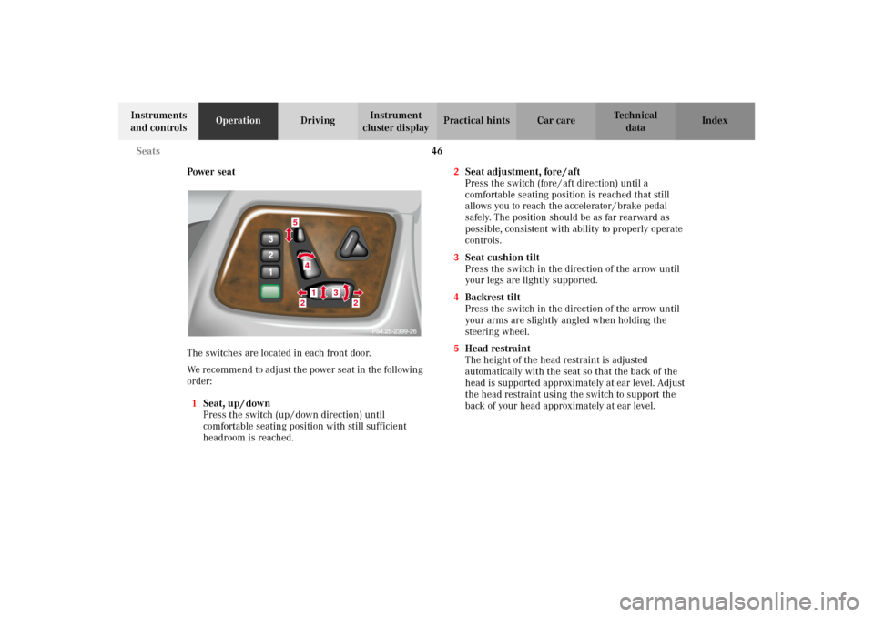
Power seat
The switches are located in each front door.
We recommend to adjust the power seat in the following
order:
1Seat, up / down
Press the switch (up / down direction) until
comfortable seating position with still sufficient
headroom is reached.2Seat adjustment, fore / aft
Press the switch (fore / aft direction) until a
comfortable seating position is reached that still
allows you to reach the accelerator / brake pedal
safely. The position should be as far rearward as
possible, consistent with ability to properly operate
controls.
3Seat cushion tilt
Press the switch in the direction of the arrow until
your legs are lightly supported.
4Backrest tilt
Press the switch in the direction of the arrow until
your arms are slightly angled when holding the
steering wheel.
5Head restraint
The height of the head restraint is adjusted
automatically with the seat so that the back of the
head is supported approximately at ear level. Adjust
the head restraint using the switch to support the
back of your head approximately at ear level.
5
41
3
2
2
J_G463.book Seite 46 Mittwoch, 19. September 2001 8:06 08
Page 171 of 385
168 Interior equipment
Te ch n i c a l
data Instruments
and controlsOperationDrivingInstrument
cluster displayPractical hints Car care Index
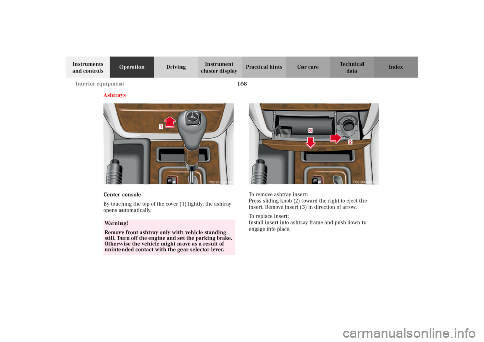
Ashtrays
Center console
By touching the top of the cover (1) lightly, the ashtray
opens automatically.To remove ashtray insert:
Press sliding knob (2) toward the right to eject the
insert. Remove insert (3) in direction of arrow.
To replace insert:
Install insert into ashtray frame and push down to
engage into place.
Wa r n i n g !
Remove front ashtray only with vehicle standing
still. Turn off the engine and set the parking brake.
Otherwise the vehicle might move as a result of
unintended contact with the gear selector lever.
1
P68.20-2265-26
J_G463.book Seite 168 Mittwoch, 19. September 2001 8:06 08
Page 194 of 385
191 The first 1 000 miles
Te ch n i c a l
data Instruments
and controlsOperationDrivingInstrument
cluster displayPractical hints Car care Index The first 1 000 miles (1 500 km)
The more cautiously you treat your vehicle during the
break-in period, the more satisfied you will be with its
performance later on. Therefore, drive your vehicle
during the first 1 000 miles (1 500 km) at moderate
vehicle and engine speeds.
During this period, avoid heavy loads (full throttle
driving) and excessive engine speeds.
Avoid accelerating by kickdown. It is not recommended
to brake t he vehicle by man ually shif tin g to a lower gear.
We recommend that you select positions “3”, “2” or “1”
only at moderate speeds (for hill driving).
After 1 000 miles (1 500 km) speeds may be gradually
increased to the permissible maximum.Maintenance
We strongly recommend that you have your vehicle
serviced by your authorized Mercedes-Benz Light Truck
Center, in accordance with the Service Booklet at the
times called for by the FSS.
Failure to have the vehicle maintained in accordance
with the Service Booklet at the designated times /
mileage may result in vehicle damage not covered by
the Mercedes-Benz Limited Warranty.
For information on the Flexible service system (FSS),
see page 124.
J_G463.book Seite 191 Mittwoch, 19. September 2001 8:06 08
Page 207 of 385
204 Starter switch
Te ch n i c a l
data Instruments
and controlsOperationDrivingInstrument
cluster displayPractical hints Car care Index
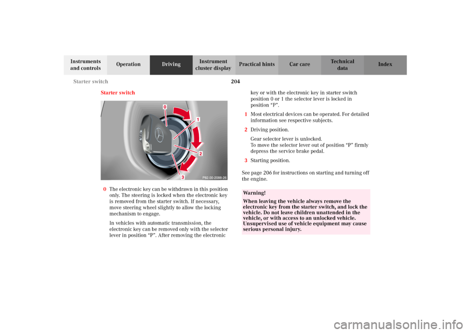
Starter switch
0The electronic key can be withdrawn in this position
only. The steering is locked when the electronic key
is removed from the starter switch. If necessary,
move steering wheel slightly to allow the locking
mechanism to engage.
In vehicles with automatic transmission, the
electronic key can be removed only with the selector
lever in position “P”. After removing the electronic key or with the electronic key in starter switch
position 0 or 1 the selector lever is locked in
position “P”.
1Most electrical devices can be operated. For detailed
information see respective subjects.
2Driving position.
Gear selector lever is unlocked.
To move the selector lever out of position “P” firmly
depress the service brake pedal.
3Starting position.
See page 206 for instructions on starting and turning off
the engine.
Wa r n i n g !
When leaving the vehicle always remove the
electronic key from the starter switch, and lock the
vehicle. Do not leave children unattended in the
vehicle, or with access to an unlocked vehicle.
Unsupervised use of vehicle equipment may cause
serious personal injury.
J_G463.book Seite 204 Mittwoch, 19. September 2001 8:06 08
Page 209 of 385
206 Starting and turning off the engine
Te ch n i c a l
data Instruments
and controlsOperationDrivingInstrument
cluster displayPractical hints Car care Index
Starting and turning off the engine
Before starting
Ensure that parking brake is engaged and that selector
lever is in position “P” or “N”. Turn electronic key in
starter switch to position 2.
Important!
In areas where temperatures frequently drop below -4
°F
(-20
°C) we recommend that an engine block heater be
installed. Your authorized Mercedes-Benz Light Truck
Center will advise you on this subject, see page 225.
Starting
Do n ot de pr ess accelerato r. B rie f ly turn electron ic key in
starter switch clockwise to the stop and release. The
starter will engage until the engine is running.
If engine will not run, and the starting procedure stops,
turn electronic key completely to the left and repeat
starting the engine.
After several unsuccessful attempts, have the system
checked at the nearest authorized Mercedes-Benz Light
Truck Center.Important!
Due to the installed starter non-repeat feature, the
electronic key must be turned completely to the left
before attempting to start the engine again.
Turning off
Turn the electronic key in the starter switch to
position 0 to stop the engine.
The electronic key can only be removed with the
selector lever in position “P”.
J_G463.book Seite 206 Mittwoch, 19. September 2001 8:06 08
Page 211 of 385
208 Automatic transmission
Te ch n i c a l
data Instruments
and controlsOperationDrivingInstrument
cluster displayPractical hints Car care Index
Driving
The selector lever is automatically locked while in
position “P”. To move the selector lever out of
position “P”, the service brake pedal must be firmly
depressed before the shift lock will release.
Shif t s elector leve r to t he d es ir ed pos ition on ly when t he
engine is idling normally and the service brake is
applied. Do not release the brake until ready to drive.
The vehicle may otherwise start creeping when the
selector lever is in drive or reverse position.Important!
After selecting any driving position from “N” or “P”,
wait a moment to allow the gear to fully engage before
accelerating, especially when the engine is cold.
Accelerator position
Partial throttle = early upshifting = normal acceleration
Full throttle = later upshifting = rapid acceleration
Kickdown (depressing the accelerator beyond full
throttle) = downshifting to a lower gear = maximum
ac celeration . On ce t he d es ire d s peed is attain ed , eas e up
on the accelerator – the transmission shifts up again.
Stopping
For brief stops, e.g. at traffic lights, leave the
transmission in gear and hold vehicle with the service
brake.
For longer stops with the engine idling, shift into “N”
or “P” and hold the vehicle with the service brake.
When stopping the vehicle on an uphill gradient, do not
hold it with the accelerator, use the brake. This avoids
unnecessary transmission heat build up.
Wa r n i n g !
It is dangerous to shift the selector lever out of “P”
or “N” if the engine speed is higher than idle speed.
If your foot is not firmly on the brake pedal, the
vehicle could accelerate quickly forward or in
reverse. You could lose control of the vehicle and
hit someone or something. Only shift into gear
when the engine is idling normally and when your
right foot is firmly on the brake pedal.
O n s l i p p e ry ro a d s u rfa c es , n eve r d ow n s h i f t i n o rd e r
to obtain braking action. This could result in drive
wheel slip and reduced vehicle control. Your
vehicle’s ABS will not prevent this type of loss of
control.
J_G463.book Seite 208 Mittwoch, 19. September 2001 8:06 08
Page 212 of 385
209 Automatic transmission
Te ch n i c a l
data Instruments
and controlsOperationDrivingInstrument
cluster displayPractical hints Car care Index Maneuvering
To maneuver in tight areas, e.g. when pulling into a
parking space, control the vehicle speed by gradually
releasing the brakes. Accelerate gently and never
abruptly step on the accelerator.
To rock a vehicle out of soft ground (mud or snow),
alternately shift from forward to reverse, while applying
slight partial throttle.
Rocking a vehicle free in this manner may cause the
ABS or traction system malfunction indicator lamp to
come on. Turn off and restart the engine to clear the
malfunction indication.
Wa r n i n g !
Getting out of your vehicle with the selector lever
not fully engaged in position “P” is dangerous.
Also, when parked on an incline, position “P” alone
may not prevent your vehicle from moving,
possibly hitting people or objects.Always set the parking brake in addition to shifting
to position “P”, see page 215 for parking brake. When parked on an incline, also turn front wheel
against curb.Wa r n i n g !
When leaving the vehicle always remove the
electronic key from the starter switch, and lock the
vehicle. Do not leave children unattended in the
vehicle, or with access to an unlocked vehicle.
Children could move the gear selector lever from
position “P”, which could result in an accident or
serious injury.
J_G463.book Seite 209 Mittwoch, 19. September 2001 8:06 08