MERCEDES-BENZ GL 2010 Owners Manual
Manufacturer: MERCEDES-BENZ, Model Year: 2010, Model line: GL, Model: MERCEDES-BENZ GL 2010Pages: 380, PDF Size: 9.81 MB
Page 191 of 380
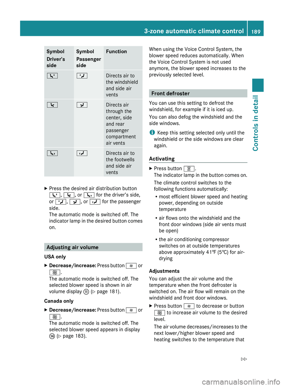
Symbol
Driver’s
sideSymbol
Passenger
sideFunctionZMDirects air to
the windshield
and side air
vents\PDirects air
through the
center, side
and rear
passenger
compartment
air ventscODirects air to
the footwells
and side air
ventsXPress the desired air distribution button
Z , \ , or c for the driver’s side,
or M , P , or O for the passenger
side.
The automatic mode is switched off. The
indicator lamp in the desired button comes
on.
Adjusting air volume
USA only
XDecrease/increase: Press button I or
K .
The automatic mode is switched off. The
selected blower speed is shown in air
volume display G (Y page 181).
Canada only
XDecrease/increase: Press button I or
K .
The automatic mode is switched off. The
selected blower speed appears in display
J (Y page 183).When using the Voice Control System, the
blower speed reduces automatically. When
the Voice Control System is not used
anymore, the blower speed increases to the
previously selected level.
Front defroster
You can use this setting to defrost the
windshield, for example if it is iced up.
You can also defog the windshield and the
side windows.
i Keep this setting selected only until the
windshield or the side windows are clear
again.
Activating
XPress button ¦.
The indicator lamp in the button comes on.
The climate control switches to the
following functions automatically:
R most efficient blower speed and heating
power, depending on outside
temperature
R air flows onto the windshield and the
front door windows (side air vents must
be open)
R the air conditioning compressor
switches on at outside temperatures
above approximately 41‡ (5†) for air-
drying
Adjustments
You can adjust the air volume and the
temperature when the front defroster is
switched on. The air flow will remain on the
windshield and front door windows.
XPress button I to decrease or button
K to increase air volume to the desired
level.
The air volume decreases/increases to the
next lower/higher blower speed and
heating switches to the temperature that3-zone automatic climate control189Controls in detailX164_AKB; 5; 31, en-USd2ureepe,Version: 2.11.8.12009-09-11T12:30:16+02:00 - Seite 189Z
Page 192 of 380
was set before the front defroster was
switched on.
The indicator lamp in button ¦ goes out.
The indicator lamp in button Á comes
on.
or
XTurn temperature control : and/or C
(USA only) ( Y page 181) or : and/or E
(Canada only) ( Y page 183) slightly in any
direction.
Heating switches to the temperature that
was set before the front defroster was
switched on.
The indicator lamp in button ¦ goes out.
The indicator lamp in button Á comes
on.
i The air conditioning compressor remains
on even if the indicator lamp in button
¦ goes out. This helps to prevent the
windshield from fogging.
Deactivating
XPress button ¦ once more.
The indicator lamp in the button goes out.
Defrosting is turned off.
The previous settings are once again in
effect. The air conditioning compressor
remains switched on.
i To deactivate, you can also press button
^ or à .
Windshield fogged on the outside
XSwitch the windshield wipers on
( Y page 103).XPress button Ã.
The indicator lamp in the button goes out.
Air volume and air distribution are
controlled separately for each zone.
If the automatic air volume and air
distribution are switched off:
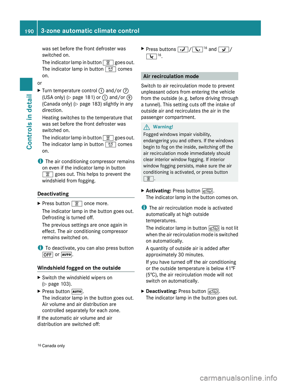
XPress buttons O/c 16
and P /
\ 16
.
Air recirculation mode
Switch to air recirculation mode to prevent
unpleasant odors from entering the vehicle
from the outside (e. g. before driving through
a tunnel). This setting cuts off the intake of
outside air and recirculates the air in the
passenger compartment.
GWarning!
Fogged windows impair visibility,
endangering you and others. If the windows
begin to fog on the inside, switching off the
air recirculation mode immediately should
clear interior window fogging. If interior
window fogging persists, make sure the air
conditioning is activated, or press button
¦ .
XActivating: Press button d.
The indicator lamp in the button comes on.
i The air recirculation mode is activated
automatically at high outside
temperatures.
The indicator lamp in button d is not lit
when the air recirculation mode is switched
on automatically.
A quantity of outside air is added after
approximately 30 minutes.
If you have turned off the air conditioning
or the outside temperature is below 41‡
(5†), the air recirculation mode will not
switch on automatically.
XDeactivating: Press button d.
The indicator lamp in the button goes out.16 Canada only1903-zone automatic climate controlControls in detail
X164_AKB; 5; 31, en-USd2ureepe,Version: 2.11.8.12009-09-11T12:30:16+02:00 - Seite 190
Page 193 of 380
iThe manually selected air recirculation
mode is deactivated automatically:
R after 5 minutes if the outside
temperature is below approximately
41‡ (5†)
R after 5 minutes if the air conditioning and
air-drying are turned off
R after 30 minutes if the outside
temperature is above approximately
41‡ (5†)
At outside temperatures above 79‡ (26†)
the system will not automatically switch back
to outside air. A quantity of outside air is
added after approximately 30 minutes.
Residual heat and ventilation
With the engine switched off, it is possible to
continue to heat or ventilate the interior for
up to 30 minutes. This feature makes use of
the residual heat produced by the engine.
i How long the system will provide heating
depends on the coolant temperature and
the battery voltage.
Regardless of the temperature and air
volume set on the climate control panel, an
interior temperature is aimed at by 72‡
(22† ) and the blower runs on low speed to
protect the vehicle battery.
XActivating: Switch off the ignition.XPress button Á.
The indicator lamp in the button comes on.XDeactivating: Press button Á again.
The indicator lamp in the button goes out.
The residual heat is deactivated
automatically:
R when the ignition is switched on
R after approximately 30 minutes
R if the battery voltage drops
R if the coolant temperature is too low
Using driver-side settings for all
temperature zones
This feature is only available in Canada
vehicles.
You can use the settings of the driver’s side,
such as temperature, air volume and air
distribution, for all temperature zones. These
settings only need to be made once and the
climate control system will automatically
regulate the settings for all temperature
zones quickly and comfortably.XActivating: Adjust the air temperature, air
volume and air distribution.XPress button ¸.
The indicator lamp in the button comes on.
The driver-side settings are used for all
temperature zones.XDeactivating: Press button ¸ again.
The indicator lamp in the button goes out.
i If you manually set the temperature, air
volume or air distribution for the passenger
side or the rear passenger compartment
when the MONO setting is active, the
MONO setting will be switched off.
Rear window defroster
GWarning!
Any accumulation of snow and ice should be
removed from the rear window before driving.
Visibility could otherwise be impaired,
endangering you and others.
The rear window defroster uses a large
amount of power. To keep the battery drain
to a minimum, switch off the defroster as
soon as the rear window is clear. The
defroster is switched off automatically after
some time of operation depending on the
outside temperature.
Rear window defroster191Controls in detailX164_AKB; 5; 31, en-USd2ureepe,Version: 2.11.8.12009-09-11T12:30:16+02:00 - Seite 191Z
Page 194 of 380
XSwitch on the ignition.XSwitching on: Press button ª on the
respective climate control panel.
The indicator lamp in the button comes on.XSwitching off: Press button ª again.
The rear window defroster switches off when
the battery voltage is too low. The indicator
lamp in button ª flashes. Too many
electrical consumers may be operating
simultaneously.
XSwitch off consumers that are currently not
needed if required.
Power tilt/sliding sunroof
Opening and closing
GObserve Safety notes, see page 55.GWarning!
When opening or closing the tilt/sliding
sunroof, make sure there is no danger of
anyone being harmed by the opening/closing
procedure.
The tilt/sliding sunroof is equipped with the
express operation and automatic reversal
function. If the movement of the tilt/sliding
sunroof is blocked during the closing
procedure, the tilt/sliding sunroof will stop
and open slightly.
The tilt/sliding sunroof operates differently
when the sunroof switch is pressed and held.
See the “Closing when the tilt/sliding sunroof
is blocked” section for details.
The opening/closing procedure of the tilt/
sliding sunroof can be immediately halted by
releasing the sunroof switch or, if the sunroof
switch was moved past the resistance point
and released, by moving the sunroof switch in
any direction.
GWarning!
The tilt/sliding sunroof is made out of glass.
In the event of an accident, the glass may
shatter. This may result in an opening in the
roof.
In a vehicle rollover, occupants not wearing
their seat belts or not wearing them properly
may be thrown out of the opening. Such an
opening also presents a potential for injury for
occupants wearing their seat belts properly as
entire body parts or portions of them may
protrude from the passenger compartment.
! To avoid damaging the seals, do not
transport any objects with sharp edges
which can stick out of the tilt/sliding
sunroof.
Do not open the tilt/sliding sunroof if there
is snow or ice on the roof, as this could
result in malfunctions.
If you cannot open or close the tilt/sliding
sunroof due to a malfunction contact
Roadside Assistance or an authorized
Mercedes-Benz Center.
! Please keep in mind that weather
conditions can sometimes change rapidly.
Make sure to close the tilt/sliding sunroof
when leaving the vehicle. If water enters
the vehicle interior, vehicle electronics
could be damaged which is not covered by
the Mercedes-Benz Limited Warranty.
i You can also open or close the tilt/sliding
sunroof using the SmartKey or the
KEYLESS-GO function, see “Summer
opening feature” ( Y page 107) and
“Convenience closing feature”
( Y page 107).
i After switching off the ignition or
removing the SmartKey from the starter
switch, you can operate the tilt/sliding
sunroof until you open the driver’s or front
passenger door. If no door was opened you
can operate the tilt/sliding sunroof for up
to 5 minutes.192Power tilt/sliding sunroofControls in detail
X164_AKB; 5; 31, en-USd2ureepe,Version: 2.11.8.12009-09-11T12:30:16+02:00 - Seite 192
Page 195 of 380
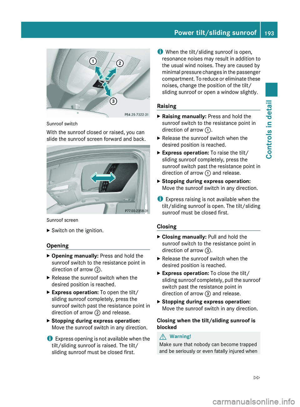
Sunroof switch
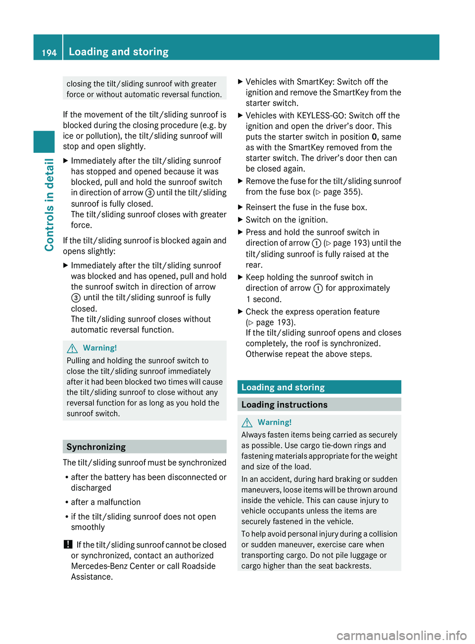
With the sunroof closed or raised, you can
slide the sunroof screen forward and back.
Sunroof screen
XSwitch on the ignition.
Opening
XOpening manually: Press and hold the
sunroof switch to the resistance point in
direction of arrow ;.
XRelease the sunroof switch when the
desired position is reached.
XExpress operation: To open the tilt/
sliding sunroof completely, press the
sunroof switch past the resistance point in
direction of arrow ; and release.
XStopping during express operation:
Move the sunroof switch in any direction.
iExpress opening is not available when the
tilt/sliding sunroof is raised. The tilt/
sliding sunroof must be closed first.
iWhen the tilt/sliding sunroof is open,
resonance noises may result in addition to
the usual wind noises. They are caused by
minimal pressure changes in the passenger
compartment. To reduce or eliminate these
noises, change the position of the tilt/
sliding sunroof or open a window slightly.
Raising
XRaising manually: Press and hold the
sunroof switch to the resistance point in
direction of arrow :.
XRelease the sunroof switch when the
desired position is reached.
XExpress operation: To raise the tilt/
sliding sunroof completely, press the
sunroof switch past the resistance point in
direction of arrow : and release.
XStopping during express operation:
Move the sunroof switch in any direction.
iExpress raising is not available when the
tilt/sliding sunroof is open. The tilt/sliding
sunroof must be closed first.
Closing
XClosing manually: Pull and hold the
sunroof switch to the resistance point in
direction of arrow =.
XRelease the sunroof switch when the
desired position is reached.
XExpress operation: To close the tilt/
sliding sunroof completely, pull the sunroof
switch past the resistance point in
direction of arrow = and release.
XStopping during express operation:
Move the sunroof switch in any direction.
Closing when the tilt/sliding sunroof is
blocked
GWarning!
Make sure that nobody can become trapped
and be seriously or even fatally injured when
Power tilt/sliding sunroof193Controls in detailX164_AKB; 5; 31, en-USd2ureepe,Version: 2.11.8.12009-09-11T12:30:16+02:00 - Seite 193Z
Page 196 of 380
closing the tilt/sliding sunroof with greater
force or without automatic reversal function.
If the movement of the tilt/sliding sunroof is
blocked during the closing procedure (e.g. by
ice or pollution), the tilt/sliding sunroof will
stop and open slightly.XImmediately after the tilt/sliding sunroof
has stopped and opened because it was
blocked, pull and hold the sunroof switch
in direction of arrow = until the tilt/sliding
sunroof is fully closed.
The tilt/sliding sunroof closes with greater
force.
If the tilt/sliding sunroof is blocked again and
opens slightly:
XImmediately after the tilt/sliding sunroof
was blocked and has opened, pull and hold
the sunroof switch in direction of arrow
= until the tilt/sliding sunroof is fully
closed.
The tilt/sliding sunroof closes without
automatic reversal function.GWarning!
Pulling and holding the sunroof switch to
close the tilt/sliding sunroof immediately
after it had been blocked two times will cause
the tilt/sliding sunroof to close without any
reversal function for as long as you hold the
sunroof switch.
Synchronizing
The tilt/sliding sunroof must be synchronized
R after the battery has been disconnected or
discharged
R after a malfunction
R if the tilt/sliding sunroof does not open
smoothly
! If the tilt/sliding sunroof cannot be closed
or synchronized, contact an authorized
Mercedes-Benz Center or call Roadside
Assistance.
XVehicles with SmartKey: Switch off the
ignition and remove the SmartKey from the
starter switch.XVehicles with KEYLESS-GO: Switch off the
ignition and open the driver’s door. This
puts the starter switch in position 0, same
as with the SmartKey removed from the
starter switch. The driver’s door then can
be closed again.XRemove the fuse for the tilt/sliding sunroof
from the fuse box ( Y page 355).XReinsert the fuse in the fuse box.XSwitch on the ignition.XPress and hold the sunroof switch in
direction of arrow : ( Y page 193) until the
tilt/sliding sunroof is fully raised at the
rear.XKeep holding the sunroof switch in
direction of arrow : for approximately
1 second.XCheck the express operation feature
( Y page 193).
If the tilt/sliding sunroof opens and closes
completely, the roof is synchronized.
Otherwise repeat the above steps.
Loading and storing
Loading instructions
GWarning!
Always fasten items being carried as securely
as possible. Use cargo tie-down rings and
fastening materials appropriate for the weight
and size of the load.
In an accident, during hard braking or sudden
maneuvers, loose items will be thrown around
inside the vehicle. This can cause injury to
vehicle occupants unless the items are
securely fastened in the vehicle.
To help avoid personal injury during a collision
or sudden maneuver, exercise care when
transporting cargo. Do not pile luggage or
cargo higher than the seat backrests.
194Loading and storingControls in detail
X164_AKB; 5; 31, en-USd2ureepe,Version: 2.11.8.12009-09-11T12:30:16+02:00 - Seite 194
Page 197 of 380
The cargo compartment is the preferred place
to carry objects. Always use cargo tie-down
rings, and if so equipped, always use the cargo
net when transporting cargo.
Never drive a vehicle with the tailgate open.
Deadly carbon monoxide (CO) gases may
enter vehicle interior resulting in
unconsciousness and death.
Load distribution
The Gross Vehicle Weight (GVW) is the weight
of the vehicle including:Rfuel
Rtools
Rspare wheel
Rinstalled accessories
Rpassengers
Rluggage/cargo
It must never exceed the load limit and the
Gross Vehicle Weight Rating (GVWR) for your
vehicle. The load limit and the GVWR are
specified on the placard located on the
driver’s door B-pillar (Y page 242).
In addition, the load must be distributed so
that the weight on each axle never exceeds
the Gross Axle Weight Rating (GAWR) for the
front and rear axle. The GVWR and GAWR for
your vehicle are indicated on the certification
label located on the driver’s door B-pillar
(Y page 242).
For more information, see “Tire and Loading
Information” (Y page 242).
The handling characteristics of a fully loaded
vehicle depend greatly on the load
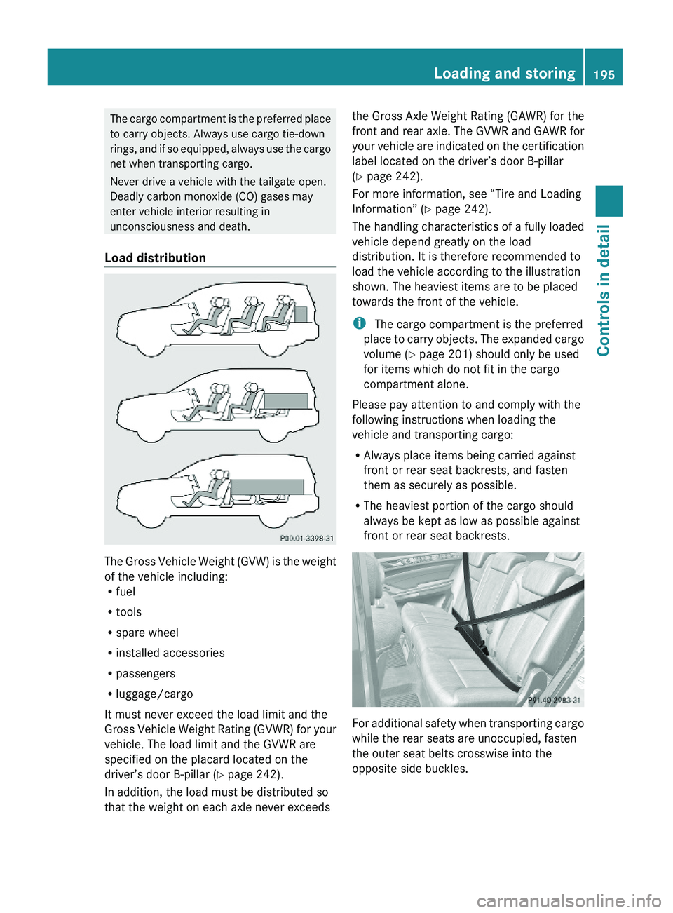
distribution. It is therefore recommended to
load the vehicle according to the illustration
shown. The heaviest items are to be placed
towards the front of the vehicle.
i The cargo compartment is the preferred
place to carry objects. The expanded cargo
volume (Y page 201) should only be used
for items which do not fit in the cargo
compartment alone.
Please pay attention to and comply with the
following instructions when loading the
vehicle and transporting cargo:
RAlways place items being carried against
front or rear seat backrests, and fasten
them as securely as possible.
RThe heaviest portion of the cargo should
always be kept as low as possible against
front or rear seat backrests.
For additional safety when transporting cargo
while the rear seats are unoccupied, fasten
the outer seat belts crosswise into the
opposite side buckles.
Loading and storing195Controls in detailX164_AKB; 5; 31, en-USd2ureepe,Version: 2.11.8.12009-09-11T12:30:16+02:00 - Seite 195Z
Page 198 of 380
Carriers
For information about further carriers,
contact an authorized Mercedes-Benz
Center.
GWarning!
Only use carriers when the crossbars have
been completely mounted. The left and right
roof rails are only stabilized by means of the
crossbars mounted.
Follow the manufacturer’s installation
instructions. Otherwise, an improperly
attached carrier or its load could become
detached from the vehicle.
Do not exceed the maximum roof load of
198 lb (90 kg).
Take into consideration that when the roof is
loaded, the handling characteristics are
different from those when operating the
vehicle without the roof loaded.
Make sure
Ryou can raise the tilt/sliding sunroof at the
rear completely
Ryou can open the tailgate completely
iThe following accessories are available
for your Mercedes-Benz:
RRoof Cargo Container – Small, Medium,
or Large
RSki and Snowboard Carrier – Standard
RSki and Snowboard Carrier – Deluxe
(Only in connection with corresponding
adapter.)
For more information on Mercedes-Benz
accessories, contact your authorized
Mercedes-Benz Center.
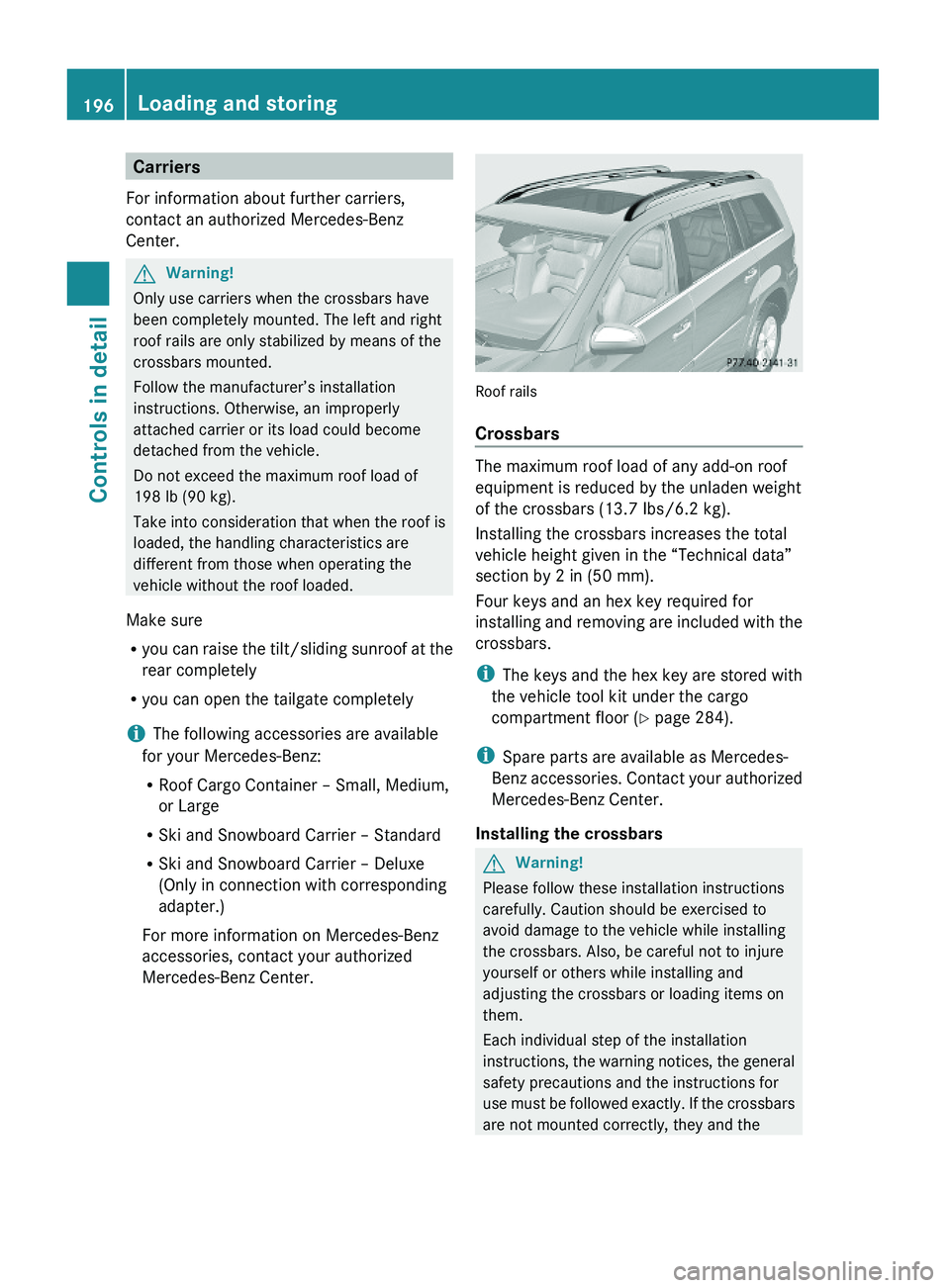
Roof rails
Crossbars
The maximum roof load of any add-on roof
equipment is reduced by the unladen weight
of the crossbars (13.7 Ibs/6.2 kg).
Installing the crossbars increases the total
vehicle height given in the “Technical data”
section by 2 in (50 mm).
Four keys and an hex key required for
installing and removing are included with the
crossbars.
iThe keys and the hex key are stored with
the vehicle tool kit under the cargo
compartment floor (Y page 284).
iSpare parts are available as Mercedes-
Benz accessories. Contact your authorized
Mercedes-Benz Center.
Installing the crossbars
GWarning!
Please follow these installation instructions
carefully. Caution should be exercised to
avoid damage to the vehicle while installing
the crossbars. Also, be careful not to injure
yourself or others while installing and
adjusting the crossbars or loading items on
them.
Each individual step of the installation
instructions, the warning notices, the general
safety precautions and the instructions for
use must be followed exactly. If the crossbars
are not mounted correctly, they and the
196Loading and storingControls in detail
X164_AKB; 5; 31, en-USd2ureepe,Version: 2.11.8.12009-09-11T12:30:16+02:00 - Seite 196
Page 199 of 380
objects attached to them could come loose
from your vehicle and cause an accident,
thereby injuring you and other persons and/
or causing damage to property, including
damage to your vehicle.GWarning!
Every time the crossbars are mounted, before
you set off on a journey and periodically
during longer journeys, check all the screws
on the crossbars to make sure that they are
secure, and tighten them if necessary. Repeat
these checks at regular intervals as road-
surface conditions dictate, and at least after
every 1500 miles (2500 km) of continuous
use.
Otherwise, the crossbars, mounted
accessories and the objects attached to them
could come loose from the vehicle causing an
accident, thereby injuring you and other
persons and/or causing damage to property,
including damage to your vehicle.
Do not use lubricant on the screws of the
crossbars. The screws could work loose and
the crossbars could become detached from
your vehicle, together with the objects
attached to them causing an accident,
thereby injuring you and other persons and/
or causing damage to property, including
damage to your vehicle.
GWarning!
Only install the crossbars at the exact
locations designated on the roof rails. The
designated locations for the front crossbars
are between the markings engraved on the
inside of the roof rails. The designated
locations for the rear crossbars are between
the gaps on the roof rails.
Otherwise, the crossbars, mounted
accessories and the objects attached to them
could come loose from the vehicle causing an
accident, thereby injuring you and other
persons and/or causing damage to property,
including damage to your vehicle.
GWarning!
A roof load creates a greater surface area
exposed to the wind and causes the vehicle
to have a higher center of gravity, thereby
changing the vehicle’s driving characteristics.
Accordingly, the additional weight on the roof
of the vehicle can have a detrimental effect
on braking, cornering and acceleration.
Never exceed the maximum permissible roof
load or the maximum permissible vehicle
weight, even when accessories for the
crossbars (e.g. ski racks, bicycle racks, etc.)
are being used. Overloading the vehicle could
result in an accident. When calculating the
weight placed on the roof please make sure
to add the weight of the crossbars, accessory
racks and the load carried together.
Always adapt your driving style to the road,
traffic and weather conditions, and drive with
added caution when the roof is loaded.
Always drive with extreme care when the
carrier is loaded. Take into consideration that
when the carrier is loaded, the handling
characteristics are different from those when
operating the vehicle without a carrier loaded.
GWarning!
Do not use accessories which have not been
approved by Mercedes-Benz for use in
conjunction with these crossbars. If non-
approved accessories are used, these
accessories and/or the objects attached to
them could come loose from the vehicle,
thereby injuring you and other persons and/
or causing damage to property, including
damage to your vehicle.
! Have a second person assist you when
installing the crossbars. The vehicle could
otherwise be damaged.
! Objects attached to the crossbar
system’s accessories must not be allowed
to restrict the movement of the tilt/sliding
sunroof. The tilt/sliding sunroof could
otherwise be damaged when it is raised.
Loading and storing197Controls in detailX164_AKB; 5; 31, en-USd2ureepe,Version: 2.11.8.12009-09-11T12:30:16+02:00 - Seite 197Z
Page 200 of 380
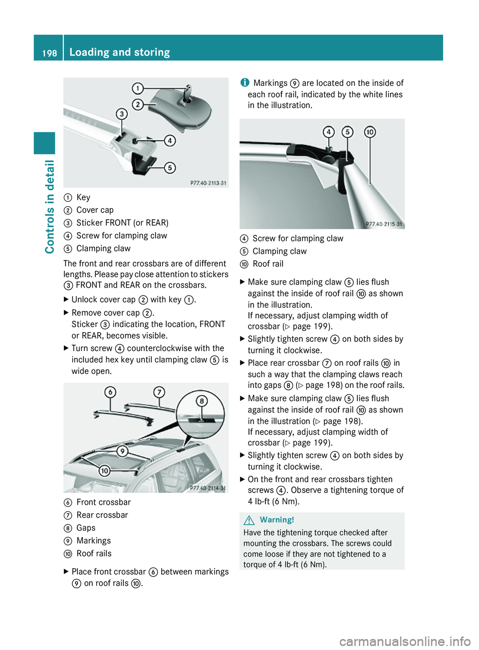
:Key;Cover cap=Sticker FRONT (or REAR)?Screw for clamping clawAClamping claw
The front and rear crossbars are of different
lengths. Please pay close attention to stickers
= FRONT and REAR on the crossbars.
XUnlock cover cap ; with key :.XRemove cover cap ;.
Sticker = indicating the location, FRONT
or REAR, becomes visible.
XTurn screw ? counterclockwise with the
included hex key until clamping claw A is
wide open.
BFront crossbarCRear crossbarDGapsEMarkingsFRoof railsXPlace front crossbar B between markings
E on roof rails F.
iMarkings E are located on the inside of
each roof rail, indicated by the white lines
in the illustration.
?Screw for clamping clawAClamping clawFRoof railXMake sure clamping claw A lies flush
against the inside of roof rail F as shown
in the illustration.
If necessary, adjust clamping width of
crossbar (Y page 199).
XSlightly tighten screw ? on both sides by
turning it clockwise.
XPlace rear crossbar C on roof rails F in
such a way that the clamping claws reach
into gaps D (Y page 198) on the roof rails.
XMake sure clamping claw A lies flush
against the inside of roof rail F as shown
in the illustration (Y page 198).
If necessary, adjust clamping width of
crossbar (Y page 199).
XSlightly tighten screw ? on both sides by
turning it clockwise.
XOn the front and rear crossbars tighten
screws ?. Observe a tightening torque of
4 lb-ft (6 Nm).
GWarning!
Have the tightening torque checked after
mounting the crossbars. The screws could
come loose if they are not tightened to a
torque of 4 lb-ft (6 Nm).
198Loading and storingControls in detail
X164_AKB; 5; 31, en-USd2ureepe,Version: 2.11.8.12009-09-11T12:30:16+02:00 - Seite 198