Light MERCEDES-BENZ GL-Class 2014 X166 Owner's Manual
[x] Cancel search | Manufacturer: MERCEDES-BENZ, Model Year: 2014, Model line: GL-Class, Model: MERCEDES-BENZ GL-Class 2014 X166Pages: 462, PDF Size: 32.46 MB
Page 348 of 462
Cargo compartment
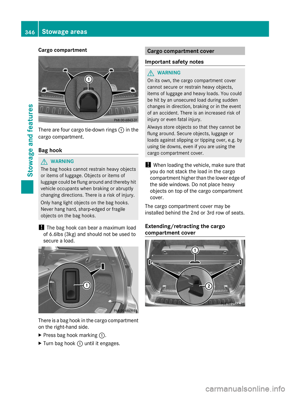
There are four cargo tie-down rings
:in the
cargo compartment.
Bag hook G
WARNING
The bag hooks cannot restrain heavy objects
or items of luggage. Objects or items of
luggage could be flung around and thereby hit
vehicle occupants when braking or abruptly
changing directions. There is a risk of injury.
Only hang light objects on the bag hooks.
Never hang hard, sharp-edged or fragile
objects on the bag hooks.
! The bag hook can bear a maximum load
of 6.6lbs (3kg) and should not be used to
secure a load. There is a bag hook in the cargo compartment
on the right-hand side.
X
Press bag hook marking :.
X Turn bag hook :until it engages. Cargo compartment cover
Important safety notes G
WARNING
On its own, the cargo compartment cover
cannot secure or restrain heavy objects,
items of luggage and heavy loads. You could
be hit by an unsecured load during sudden
changes in direction, braking or in the event
of an accident. There is an increased risk of
injury or even fatal injury.
Always store objects so that they cannot be
flung around. Secure objects, luggage or
loads against slipping or tipping over, e.g. by
using tie downs, even if you are using the
cargo compartment cover.
! When loading the vehicle, make sure that
you do not stack the load in the cargo
compartment higher than the lower edge of
the side windows. Do not place heavy
objects on top of the cargo compartment
cover.
The cargo compartment cover may be
installed behind the 2nd or 3rd row of seats.
Extending/retracting the cargo
compartment cover 346
Stowage areasStowage and features
Page 351 of 462
R
Always stow objects so that they cannot be
thrown around in such situations.
R Always make sure that objects do not
protrude from stowage spaces, parcel nets
or stowage nets.
R Close the lockable stowage spaces while
driving.
R Stow and secure objects that are heavy,
hard, pointy, sharp-edged, fragile or too
large in the cargo compartment.
! Only use the cup holders for containers of
the right size and which have lids. The
drinks could otherwise spill.
The stowage compartments in the doors
provide space for bottles with a capacity of
up to 34 fl. oz. (1.0 l).
The bottles are not secured or prevented from
tipping over. Therefore, do not place any open
drink containers in the stowage
compartments.
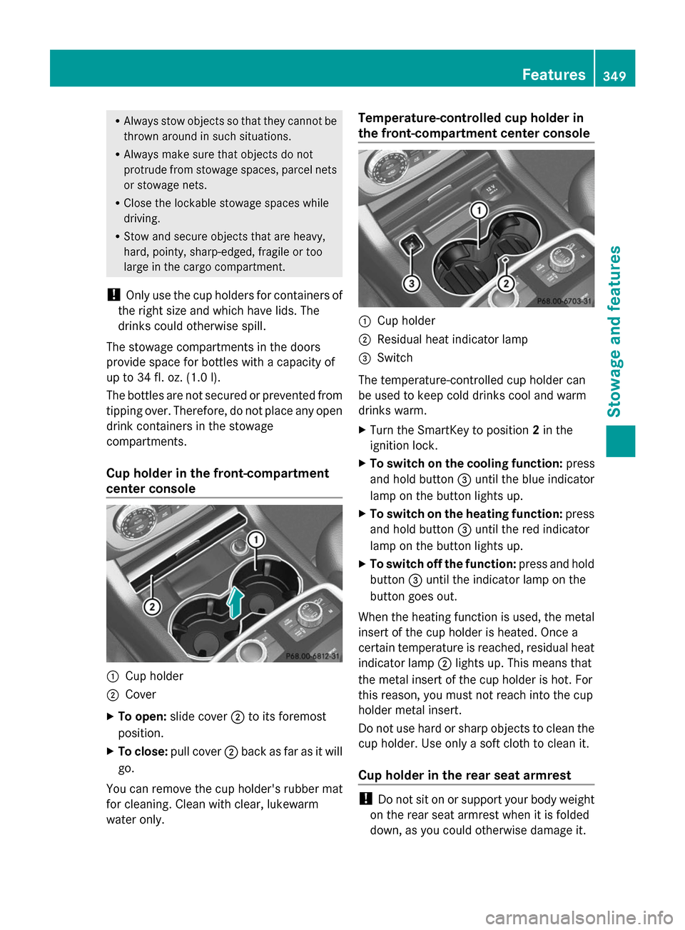
Cup holder in the front-compartment
center console :
Cup holder
; Cover
X To open: slide cover ;to its foremost
position.
X To close: pull cover ;back as far as it will
go.
You can remove the cup holder's rubber mat
for cleaning. Clean with clear, lukewarm
water only. Temperature-controlled cup holder in
the front-compartment center console
:
Cup holder
; Residual heat indicator lamp
= Switch
The temperature-controlled cup holder can
be used to keep cold drinks cool and warm
drinks warm.
X Turn the SmartKey to position 2in the
ignition lock.
X To switch on the cooling function: press
and hold button =until the blue indicator
lamp on the button lights up.
X To switch on the heating function: press
and hold button =until the red indicator
lamp on the button lights up.
X To switch off the function: press and hold
button =until the indicator lamp on the
button goes out.
When the heating function is used, the metal
insert of the cup holder is heated. Once a
certain temperature is reached, residual heat
indicator lamp ;lights up. This means that
the metal insert of the cup holder is hot. For
this reason, you must not reach into the cup
holder metal insert.
Do not use hard or sharp objects to clean the
cup holder. Use only a soft cloth to clean it.
Cup holder in the rear seat armrest !
Do not sit on or support your body weight
on the rear seat armrest when it is folded
down, as you could otherwise damage it. Features
349Stowage an d features Z
Page 352 of 462
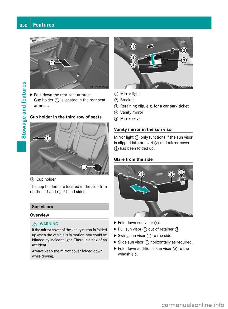
X
Fold down the rear seat armrest.
Cup holder :is located in the rear seat
armrest.
Cup holder in the third row of seats :
Cup holder
The cup holders are located in the side trim
on the left and right-hand sides. Sun visors
Overview G
WARNING
If the mirror cover of the vanity mirror is folded
up when the vehicle is in motion, you could be
blinded by incident light. There is a risk of an
accident.
Always keep the mirror cover folded down
while driving. :
Mirror light
; Bracket
= Retaining clip, e.g. for a car park ticket
? Vanity mirror
A Mirror cover
Vanity mirror in the sun visor Mirror light
:only functions if the sun visor
is clipped into bracket ;and mirror cover
A has been folded up.
Glare from the side X
Fold down sun visor :.
X Pull sun visor :out of retainer =.
X Swing sun visor :to the side.
X Slide sun visor :horizontally as required.
X Fold down additional sun visor ;to the
windshield. 350
FeaturesStowage and features
Page 353 of 462
Roller sunblinds on the rear side
windows
! Always guide the roller sunblind by hand.
Do not let it snap back suddenly as this
would damage the automatic roller
mechanism.
! Do not drive the vehicle with the roller
sunblind hooked in and the side windows
opened simultaneously. The roller sunblind
can jump out of the retainers and spring
back suddenly when driving at high speeds,
e.g. when driving on the freeway. This could
damage the inertia reel. Therefore, either
close the side window or retract the roller
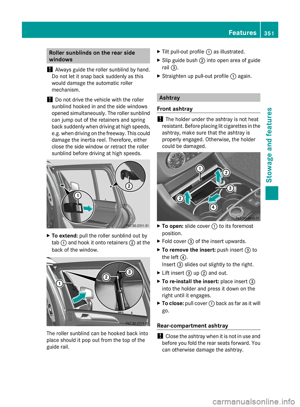
sunblind before driving at high speeds. X
To extend: pull the roller sunblind out by
tab :and hook it onto retainers ;at the
back of the window. The roller sunblind can be hooked back into
place should it pop out from the top of the
guide rail. X
Tilt pull-out profile :as illustrated.
X Slip guide bush ;into open area of guide
rail =.
X Straighten up pull-out profile :again. Ashtray
Front ashtray !
The holder under the ashtray is not heat
resistant. Before placing lit cigarettes in the
ashtray, make sure that the ashtray is
properly engaged. Otherwise, the holder
could be damaged. X
To open: slide cover :to its foremost
position.
X Fold cover =of the insert upwards.
X To remove the insert: push insert=to
the left ?.
Insert =slides out slightly to the right.
X Lift insert =up; and out.
X To re-install the insert: place insert=
into the holder and press it down on the
right until it engages.
X To close: pull cover :back as far as it will
go.
Rear-compartment ashtray !
Close the ashtray when it is not in use and
before you fold the rear seats forward. You
can otherwise damage the ashtray. Features
351Stowage and features Z
Page 354 of 462
X
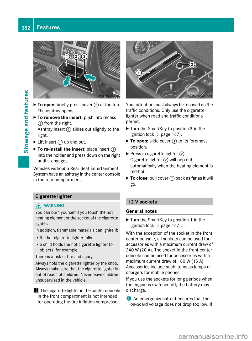
To open: briefly press cover ;at the top.
The ashtray opens.
X To remove the insert: push into recess
= from the right.
Ashtray insert :slides out slightly to the
right.
X Lift insert :up and out.
X To re-install the insert: place insert:
into the holder and press down on the right
until it engages.
Vehicles without a Rear Seat Entertainment
System have an ashtray in the center console
in the rear compartment. Cigarette lighter
G
WARNING
You can burn yourself if you touch the hot
heating element or the socket of the cigarette
lighter.
In addition, flammable materials can ignite if:
R the hot cigarette lighter falls
R a child holds the hot cigarette lighter to
objects, for example
There is a risk of fire and injury.
Always hold the cigarette lighter by the knob.
Always make sure that the cigarette lighter is
out of reach of children. Never leave children
unsupervised in the vehicle.
! The cigarette lighter in the center console
in the front compartment is not intended
for operating the tire inflation compressor. Your attention must always be focused on the
traffic conditions. Only use the cigarette
lighter when road and traffic conditions
permit.
X
Turn the SmartKey to position 2in the
ignition lock (Y page 167).
X To open: slide cover :to its foremost
position.
X Press in cigarette lighter ;.
Cigarette lighter ;will pop out
automatically when the heating element is
red-hot.
X To close: pull cover :back as far as it will
go. 12 V sockets
General notes X
Turn the SmartKey to position 1in the
ignition lock (Y page 167).
With the exception of the socket in the front
center console, all sockets can be used for
accessories with a maximum current draw of
240 W (20 A). The socket in the front center
console can be used for accessories with a
maximum current draw of 180 W (15 A).
Accessories include such items as lamps or
chargers for mobile phones.
If you use the sockets for long periods when
the engine is switched off, the battery may
discharge.
i An emergency cut-out ensures that the
on-board voltage does not drop too low. If 352
FeaturesSto
wage an d features
Page 356 of 462
!
Note that work and repairs on the 115 V
power socket should only be carried out by
qualified specialist personnel.
General notes 115 V power socket provides an alternating
voltage of 115 V so that small electronic
devices can be connected. These devices,
such as games consoles, chargers and
laptops, should not consume more than a
maximum of 150 watts altogether.
Requirements for operation of these devices:
R the electronic device that you connect has
a suitable connector and conforms to
standards specific to the country you are
in.
R the plug of the electronic device is plugged
correctly into 115 V power socket.
R the maximum wattage of the device to be
connected must not exceed 150 watts.
R the on-board power supply is within a
permissible voltage range.
R the 12 V sockets in the rear compartment
and the cargo compartment are
operational.
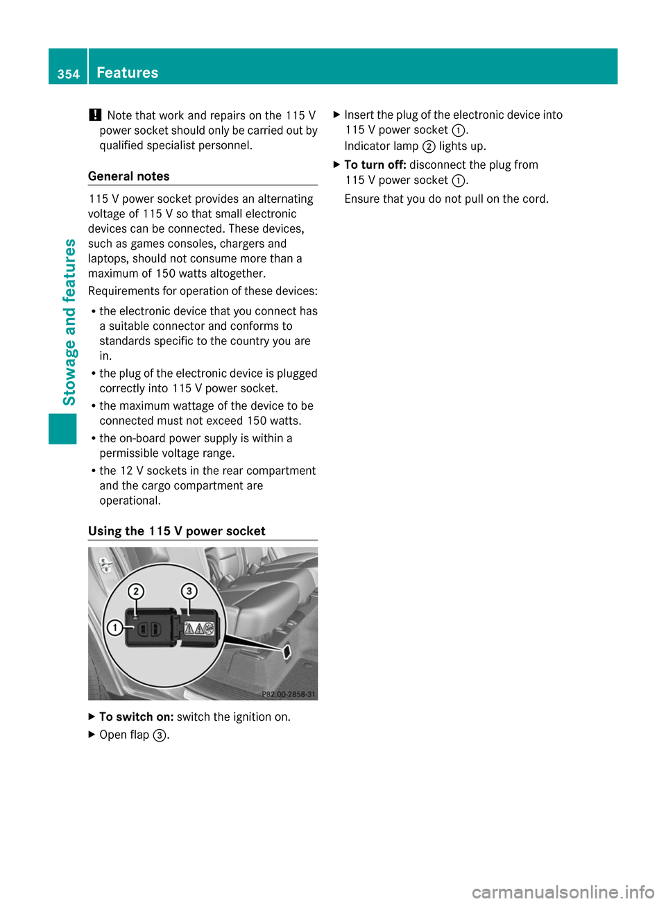
Using the 115 V power socket X
To switch on: switch the ignition on.
X Open flap =. X
Insert the plug of the electronic device into
115 V power socket :.
Indicator lamp ;lights up.
X To turn off: disconnect the plug from
115 V power socket :.
Ensure that you do not pull on the cord. 354
FeaturesStowage and features
Page 357 of 462
Problems with the 115 V power socket
Problem Possible causes/consequences and
M
MSolutions The warning lamp on
the 115 V power socket
is not lit. The on-board voltage is too low because the battery is too weak.
X
Start the engine.
or
X Charge the battery (Y page 394).
If the indicator lamp still does not light up:
X Visit a qualified specialist workshop. The temperature of the DC/AC converter is temporarily too high.
X
Remove the electronic device connector from the 115 V socket.
X Let the DC/AC converter cool down.
If the indicator lamp still does not light up after cooling down the
converter:
X Visit a qualified specialist workshop. You have connected an electronic device that has a constant
nominal power of less than 150 watts, but a very high switch-on
current. This device will not work. If you connect such a device,
the 115 V power socket will not supply it with power.
X
Connect a suitable device. mbrace
General notes You must have a license agreement to
activate the mbrace service. Make sure that
your system is activated and operational. To
log in, press the ïMB Info call button. If
any of the steps mentioned are not carried
out, the system may not be activated.
If you have questions about the activation,
contact one of the following telephone
hotlines:
R USA: Mercedes-Benz Customer Assistance
Center at
1-800-FOR-MERCedes (1-800-367-6372)
or 1-866-990-9007
R Canada: Customer Service at
1-888-923-8367 Shortly after successfully registering with the
service, a user ID and password will be sent
to you by post.
USA only: you can use this password to log
onto the mbrace area under "Owners Online"
at
http://www.mbusa.com.
The system is available if:
R it has been activated and is operational
R the corresponding mobile phone network
is available for transmitting data to the
Customer Center
R a service subscription is available
R the starter battery is sufficiently charged
i Determining the location of the vehicle on
a map is only possible if:
R GPS reception is available.
R the vehicle position can be forwarded to
the Customer Assistance Center. Features
355Stowage and features Z
Page 358 of 462
The mbrace system
To adjust the volume during a call, proceed
as follows:
X Press the WorX button on the
multifunction steering wheel.
or
X Use the volume controller of the audio
system/COMAND.
The system offers various services, e.g.:
R Automatic and manual emergency call
R Roadside Assistance call
R MB Info call
USA only: you can find information and a
description of all available features under
"Owners Online" at http://www.mbusa.com.
System self-test After you have switched on the ignition, the
system carries out a self-diagnosis.
A malfunction in the system has been
detected if one of the following occurs:
R The indicator lamp in the SOS button does
not come on during the system self-test.
R The indicator lamp in the FRoadside
Assistance button does not light up during
self-diagnosis of the system.
R The indicator lamp in the ïMB Info call
button does not light up during self-
diagnosis of the system.
R The indicator lamp in one or more of the
following buttons continues to light up red
after the system self-diagnosis:
- SOS button
- F Roadside Assistance call button
- ï MB Info call button
R After the system self-diagnosis, the
Inoperative
Inoperative orService Not Service Not
Activated
Activated message appears in the
multifunction display.
If a malfunction is indicated as outlined
above, the system may not operate as expected. In the event of an emergency, help
will have to be summoned by other means.
Have the system checked at the nearest
authorized Mercedes-Benz Center or contact
the following service hotlines:
R
USA: Mercedes-Benz Customer Assistance
Center at
1-800-FOR-MERCedes (1-800-367-6372)
or 1-866-990-9007
R Canada: Customer Service at
1-888-923-8367
Emergency call Important safety notes
G
WARNING
It can be dangerous to remain in the vehicle,
even if you have pressed the SOS button in an
emergency if:
R you see smoke inside or outside of the
vehicle, e.g. if there is a fire after an
accident
R the vehicle is on a dangerous section of
road
R the vehicle is not visible or cannot easily be
seen by other road users, particularly when
dark or in poor visibility conditions
There is a risk of an accident and injury.
Leave the vehicle immediately in this or
similar situations as soon as it is safe to do
so. Move to a safe location along with other
vehicle occupants. In such situations, secure
the vehicle in accordance with national
regulations, e. g. with a warning triangle.
You must have a license agreement to
activate the mbrace service. Make sure that
your system is activated and operational. To
register, press the ïMB Info call button.
If any of the steps mentioned are not carried
out, the system may not be activated. 356
FeaturesSto
wage an d features
Page 366 of 462
Triggering the vehicle alarm
With this function, you can trigger the
vehicle's panic alarm via text message. An
alarm sounds and the exterior lighting
flashes. Depending on the setting, the panic
alarm lasts five or ten seconds. Afterwards,
the alarm switches off. Garage door opener
General notes The HomeLink
®
garage door opener
integrated in the rear-view mirror allows you
to operate up to three different door and gate
systems.
Use the integrated garage door opener only
on garage doors that:
R have safety stop and reverse features and
R meet current U.S. federal safety standards
Once programed, the integrated garage door
opener in the rear-view mirror will assume the
function of the garage door system's remote
control. Please also read the operating
instructions for the garage door system.
When programing a garage door opener, park
the vehicle outside the garage. Do not run the
engine while programing.
Certain garage door drives are incompatible
with the integrated garage door opener. If you
have difficulty programing the integrated
garage door opener, contact an authorized
Mercedes-Benz Center.
Alternatively, you can call the following
telephone assistance services:
R USA: Mercedes-Benz Customer Assistance
Center at 1-800-FOR-MERCedes
R Canada: Customer Service at
1-800-387-0100
R HomeLink ®
hotline 1-800-355-3515 (free
of charge)
More information on HomeLink ®
and/or
compatible products is also available online
at http://www.homelink.com. Notes on the declaration of conformity
(Y
page 27).
USA: FCC ID: CB2HMIHL4
Canada: IC: 279B-HMIHL4
Important safety notes G
WARNING
When you operate or program the garage door
with the integrated garage door opener,
persons in the range of movement of the
garage door can become trapped or struck by
the garage door. There is a risk of injury.
When using the integrated garage door
opener, always make sure that nobody is
within the range of movement of the garage
door. G
WARNING
Combustion engines emit poisonous exhaust
gases such as carbon monoxide. Inhaling
these exhaust gases leads to poisoning. There
is a risk of fatal injury. Therefore never leave
the engine running in enclosed spaces
without sufficient ventilation.
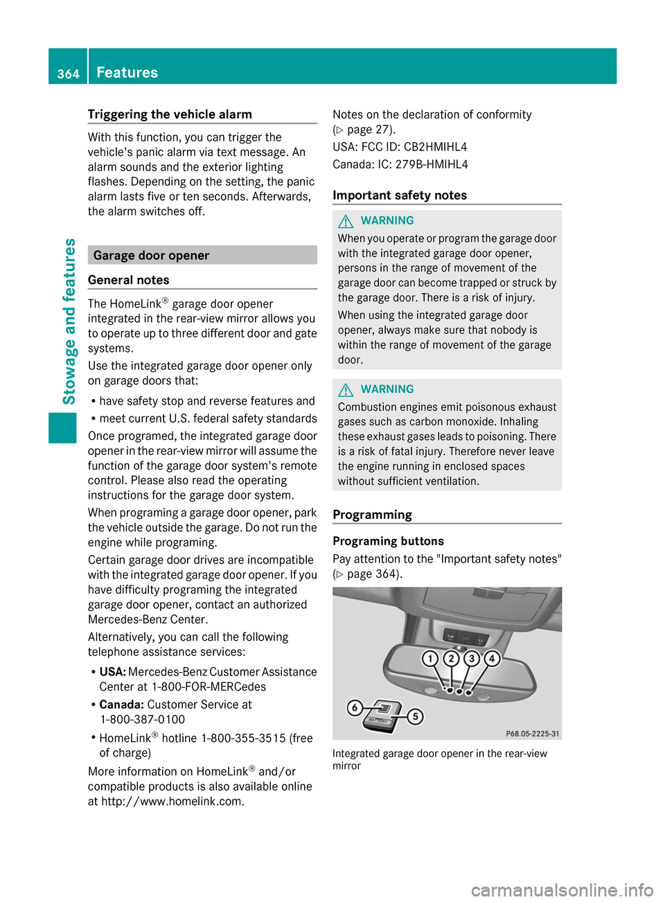
Programming Programing buttons
Pay attention to the "Important safety notes"
(Y
page 364). Integrated garage door opener in the rear-view
mirror 364
FeaturesSto
wage an d features
Page 367 of 462
Garage door remote control
Ais not
included with the integrated garage door
opener.
X Turn the SmartKey to position 2in the
ignition lock (Y page 167).
X Select one of buttons ;to? to use to
control the garage door drive.
X To start programing mode: press and
hold one of buttons ;to? of the
integrated garage door opener.
The garage door opener is now in
programing mode. After a short time,
indicator lamp :lights up yellow.
Indicator lamp :lights up yellow as soon
as button ;,=or? is programed for the
first time. If the selected button has already
been programed, indicator lamp :will
only light up yellow after ten seconds have
elapsed.
X Release button ;,=or?. Indicator
lamp :flashes yellow.
X To program the remote control: point
garage door remote control Atowards
buttons ;to? on the rear-view mirror at
a distance of 2 to 8 inches (5 to 20 cm).
X Press and hold button Bon remote control
A until indicator lamp :lights up green.
When indicator lamp :lights up green:
programing is finished.
When indicator lamp :flashes green:
programing was successful. The next step
is to synchronize the rolling code.
X Release button Bon remote control Afor
the garage door drive system.
If indicator lamp :lights up red: repeat
the programing procedure for the
corresponding button on the rear-view
mirror. When doing so, vary the distance
between remote control Aand the rear-
view mirror.
The required distance between remote
control Aand the integrated garage door
opener depends on the garage door drive
system. Several attempts might be necessary. You should test every position
for at least 25 seconds before trying
another position.
Synchronizing the rolling code
Pay attention to the "Important safety notes"
(Y page 364).
If the garage door system uses a rolling code,
you will also have to synchronize the garage
door system with the integrated garage door
opener in the rear-view mirror. To do this you
will need to use the programing button on the
door drive control panel. The programing
button may be placed at different locations
depending on the manufacturer. It is usually
located on the door drive unit on the garage
ceiling.
Familiarize yourself with the garage door
drive operating instructions, e.g. under
"Programing of additional remote controls",
before carrying out the following steps.
Your vehicle must be within reach of the
garage door or exterior gate drive. Make sure
that neither your vehicle nor any persons/
objects are present within the sweep of the
door or gate.
X Turn the SmartKey to position 2in the
ignition lock (Y page 167).
X Get out of the vehicle.
X Press the programing button on the door
drive unit.
Usually, you now have 30 seconds to
initiate the next step.
X Get into the vehicle.
X Press previously programed button ;,=
or ? of the integrated garage door opener
until the door closes.
The rolling code synchronization is then
complete.
Notes on programing the remote control
Canadian radio frequency laws require a
"break" (or interruption) of the transmission
signals after broadcasting for a few seconds.
Therefore, these signals may not last long
enough for the integrated garage door Features
365Stowage and featu res Z