ECU MERCEDES-BENZ GL-Class 2016 X166 Manual Online
[x] Cancel search | Manufacturer: MERCEDES-BENZ, Model Year: 2016, Model line: GL-Class, Model: MERCEDES-BENZ GL-Class 2016 X166Pages: 462, PDF Size: 10.44 MB
Page 395 of 462
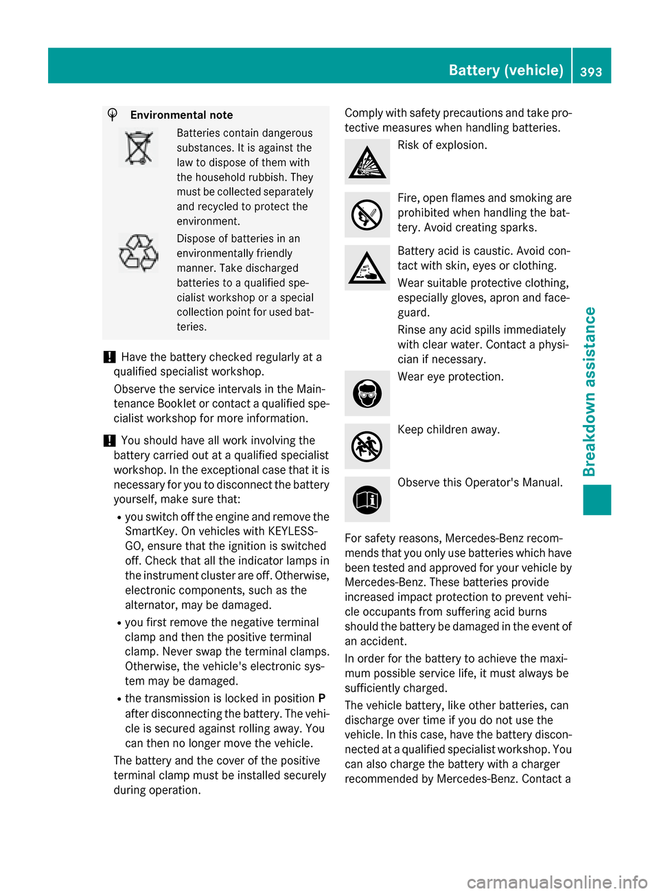
HEnvironmental note
Batteries contain dangerous
substances. It is against the
law to dispose of them with
the household rubbish. They
must be collected separatelyand recycled to protect the
environment.
Dispose of batteries in an
environmentally friendly
manner. Take discharged
batteries to a qualified spe-
cialist workshop or a special
collection point for used bat-
teries.
!Have the battery checked regularly at a
qualified specialist workshop.
Observe the service intervals in the Main-
tenance Booklet or contact a qualified spe-
cialist workshop for more information.
!You should have all work involving the
battery carried out at a qualified specialist
workshop. In the exceptional case that it is
necessary for you to disconnect the battery
yourself, make sure that:
Ryou switch off the engine and remove the
SmartKey. On vehicles with KEYLESS-
GO, ensure that the ignition is switched
off. Check that all the indicator lamps in
the instrument cluster are off. Otherwise, electronic components, such as the
alternator, may be damaged.
Ryou first remove the negative terminal
clamp and then the positive terminal
clamp. Never swap the terminal clamps.
Otherwise, the vehicle's electronic sys-
tem may be damaged.
Rthe transmission is locked in position P
after disconnecting the battery. The vehi-
cle is secured against rolling away. You
can then no longer move the vehicle.
The battery and the cover of the positive
terminal clamp must be installed securely
during operation. Comply with safety precautions and take pro-
tective measures when hand
ling bat
teries.
Risk of explosion.
Fire, open flames and smoking are
prohibited when handling the bat-
tery. Avoid creating sparks.
Battery acid is caustic. Avoid con-
tact with skin, eyes or clothing.
Wear suitable protective clothing,
especially gloves, apron and face-
guard.
Rinse any acid spills immediately
with clear water. Contact a physi-
cian if necessary.
Wear eye protection.
Keep children away.
Observe this Operator's Manual.
For safety reasons, Mercedes-Benz recom-
mends that you only use batteries which have
been tested and approved for your vehicle by
Mercedes-Benz. These batteries provide
increased impact protection to prevent vehi-
cle occupants from suffering acid burns
should the battery be damaged in the event of
an accident.
In order for the battery to achieve the maxi-
mum possible service life, it must always be
sufficiently charged.
The vehicle battery, like other batteries, can
discharge over time if you do not use the
vehicle. In this case, have the battery discon- nected at a qualified specialist workshop. You
can also charge the battery with a charger
recommended by Mercedes-Benz. Contact a
Battery (vehicle)393
Breakdown assistance
Z
Page 398 of 462
Do not start the vehicle using a rapid charging device. If your vehicle's battery is discharged,
the engine can be jump-started from another vehicle or from a second battery using jumper
cables. Observe the following points:
RThe battery is not accessible in all vehicles. If the other vehicle's battery is not accessible,
jump-start the vehicle using a second battery or a jump-starting device.
RVehicles with a gasoline engine:only jump-start the vehicle when the engine and exhaust
system are cold.
RDo not start the engine if the battery is frozen. Let the battery thaw first.
ROnly jump-start from batteries with a 12 V voltage rating.
ROnly use jumper cables which have a sufficient cross-section and insulated terminal clamps.
RIf the battery is fully discharged, leave the battery that is being used to jump-start connected
for a few minutes before attempting to start. This charges the battery slightly.
RMake sure that the two vehicles do not touch.
Make sure that:
RThe jumper cables are not damaged.
RBare parts of the terminal clamp do not come into contact with other metal parts while the
jumper cables are conne cted to th
e battery.
RThe jumper cables cannot come into contact with parts which can move when the engine is
running, such as the V-belt pulley or the fan.
XSecure the vehicle by applying the electric parking brake.
XShift the transmission to position P.
XTurn the SmartKey to position 0in the ignition lock and remove it (Ypage 165). On vehicles
with KEYLESS-GO, make sure the ignition is switched off (
Ypage 165). All indicator lamps
in the instrument cluster must be off.
XSwitch off all electrical consumers, e.g. rear window defroster, lighting, etc.
XOpen the hood.
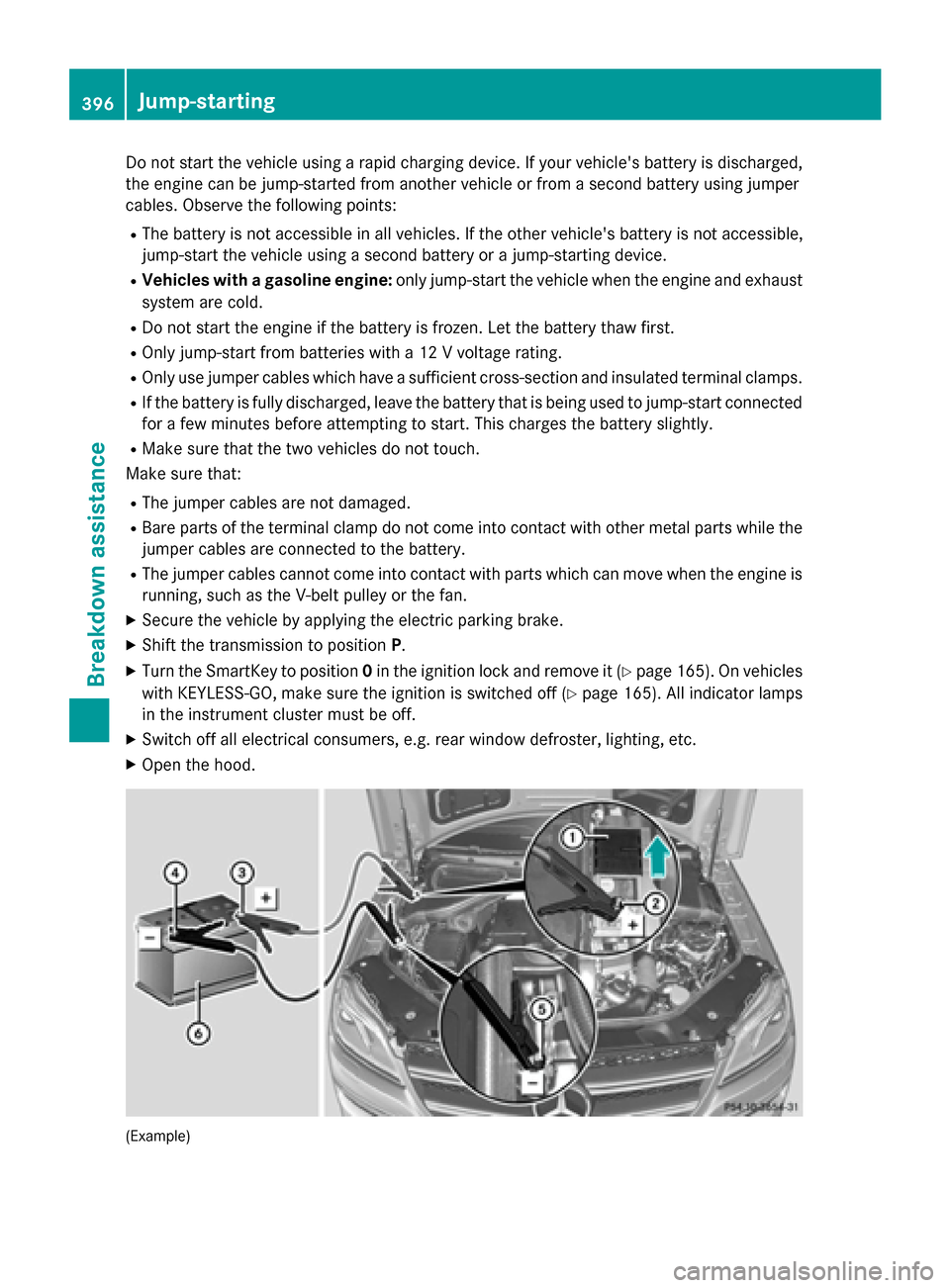
(Example)
396Jump-starting
Breakdown assistance
Page 400 of 462
To prevent damage to the vehicle, deacti-
vate DISTRONIC PLUS and the HOLD func-tion in the following or other similar situa-
tions:
Rwhen towing the vehicle
Rin the car wash
!Make sure that the electric parking brake
is released. If the electric parking brake is
faulty, visit a qualified specialist workshop.
!Only secure the tow rope or tow bar at the
towing eyes. Otherwise, the vehicle could
be damaged.
!Do not use the trailer tow hitch for recov-
ery or towing. Do not use the towing eye for recovery. this could damage the vehicle. If
in doubt, have the vehicle recovered using
a crane.
!When towing, pull away slowly and
smoothly. Pull the towed vehicle as straight
as possible and not at an acute angle.
Excessive tractive power could damage the
vehicles.
iWhen towing, it is preferable to use a rigid
towing bar as opposed to a tow rope. A rigid towing bar helps to keep the tractive power
low.
!When towing vehicles with KEYLESS-GO,
use the key instead of the Start/Stop but-
ton. Otherwise, the automatic transmission
may shift to position Pwhen the driver's or
front-passenger door are opened, which
could lead to damage to the transmission.
!Do not tow with sling-type equipment.
This could damage the vehicle.
!Vehicles with differential locks: make
sure the differential locks are in automatic
mode. When towing, the differential locks
must not be switched on. The transmission may otherwise be damaged.
!The vehicle can be towed a maximum of
30 miles (50km). The towing speed of
30 mph (50 km/h) must not be exceeded. If the vehicle has to be towed more than
30 miles (50km), the entire vehicle must be
raised and transported.
It is better to have the vehicle transported
than to have it towed away.
If the vehicle has suffered transmission dam-
age, have it transported on a transporter or
trailer.
The automatic transmission must be in posi-
tion Nwhen the vehicle is being towed.
The battery must be connected and charged.
Otherwise, you:
Rcannot turn the SmartKey to position 2in
the ignition lock
Rcannot release the electric parking brake
Rcannot shift the automatic transmission to position N
iDisarm the automatic locking feature
(
Ypage 285). You could otherwise be
locked out when pushing or towing the
vehicle.
Installing/removing the towing eye
Installing the towing eye
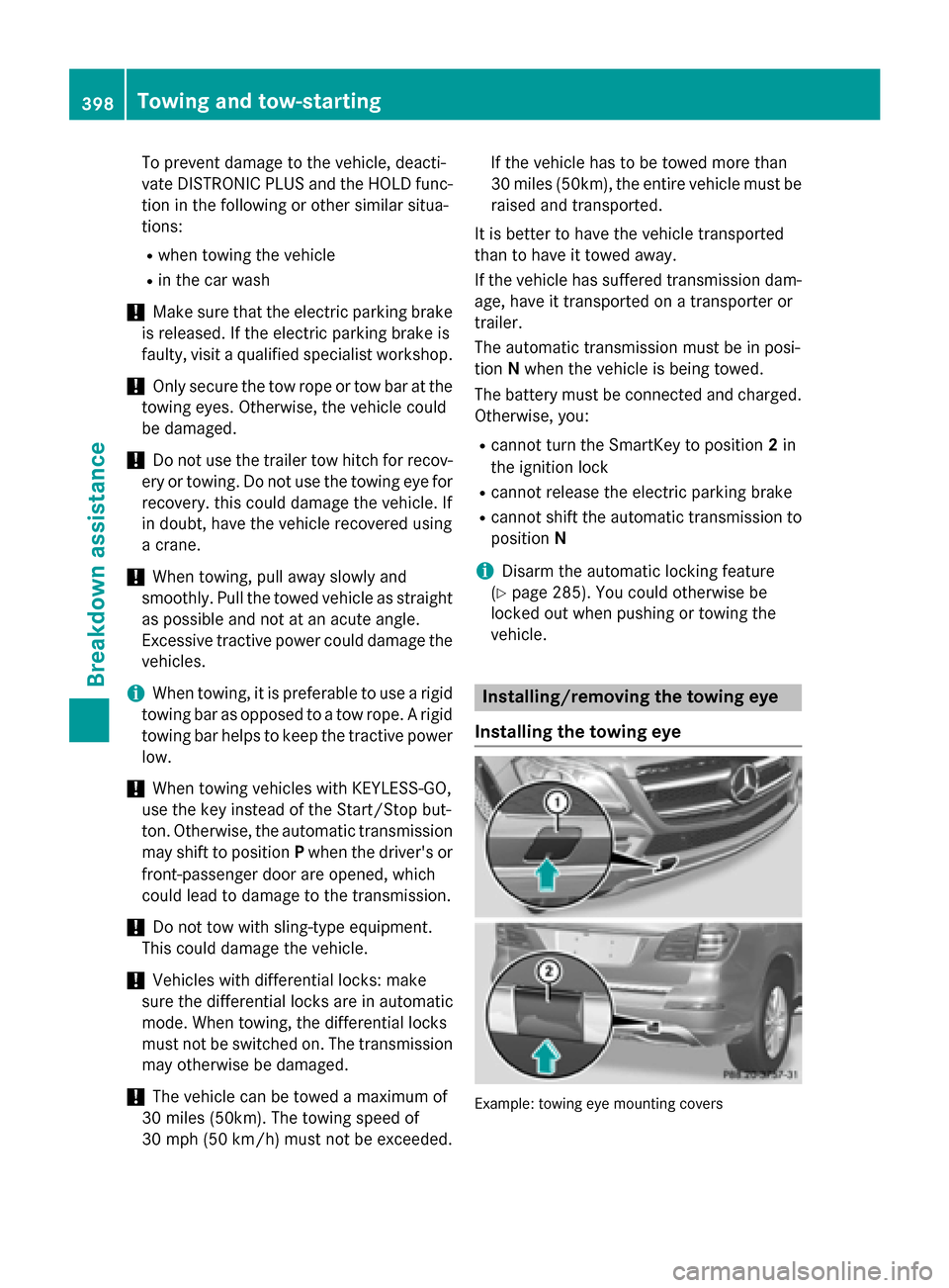
Example: towing eye mounting covers
398Towing and tow-starting
Breakdown assistance
Page 401 of 462
The brackets for the screw-in towing eyes are
located in the bumpers. They are at the front
and at the rear, behind the covers.
XRemove the towing eye from the vehicle
tool kit (
Ypage 386).
XTo open the cover at the front:press the
mark on cover :inwards in the direction
of the arrow.
XTo open the cover at the rear: insert a
flat, blunt object into the cutout and lever
cover ;out of the bumper.
XTake cover :or; off the opening.
XScrew in the towing eye clockwise as far as
it will go and tighten it.
Removing the towing eye
XUnscrew and remove the towing eye.
XAttach cover :or; to the bumper and
press until it engages.
XPlace the towing eye in the vehicle tool kit.
Towing a vehicle with both axles on
the ground
It is important that you observe the safety
instructions when towing away your vehicle
(
Ypage 397).
The automatic transmission automatically
shifts to position Pwhen you open the driver's
or front-passenger door or when you remove
the SmartKey from the ignition lock.
In order to ensure that the automatic trans-
mission stays in position Nwhen towing the
vehicle, you must observe the following
points:
XMake sure that the vehicle is stationary and
the SmartKey in the ignition lock is in posi-
tion 0.
XTurn the SmartKey to position 2in the igni-
tion lock.
On vehicles with KEYLESS-GO, use the
SmartKey instead of the Start/Stop button
(
Ypage 165).
XDepress and hold the brake pedal.
XShift the automatic transmission to posi-
tion N.
XRelease the brake pedal.
XRelease the electric parking brake.
XLeave the SmartKey in position 2in the
ignition lock.
XSwitch on the hazard warning lamps
(
Ypage 133).
iIn order to signal a change of direction
when towing the vehicle with the hazard
warning lamps switched on, use the com-
bination switch as usual. In this case, only
the indicator lamps for the direction of
travel flash. After resetting the combina-
tion switch, the hazard warning lamp starts
flashing again.
Transporting the vehicle
!
You may only secure the vehicle by the
wheels, not by parts of the vehicle such as
axle or steering components. Otherwise,
the vehicle could be damaged.
The towing eye can be used to pull the vehicle
onto a trailer or transporter for transporting
purposes.
XTurn the SmartKey to position 2in the igni-
tion lock.
XShift the automatic transmission to posi-
tion N.
As soon as the vehicle has been loaded:
XPrevent the vehicle from rolling away by
applying the electric parking brake.
XShift the automatic transmission to posi-
tion P.
XTurn the SmartKey to position 0in the igni-
tion lock and remove it.
XSecure the vehicle.
Towing and tow-starting399
Breakdown assistance
Z
Page 413 of 462
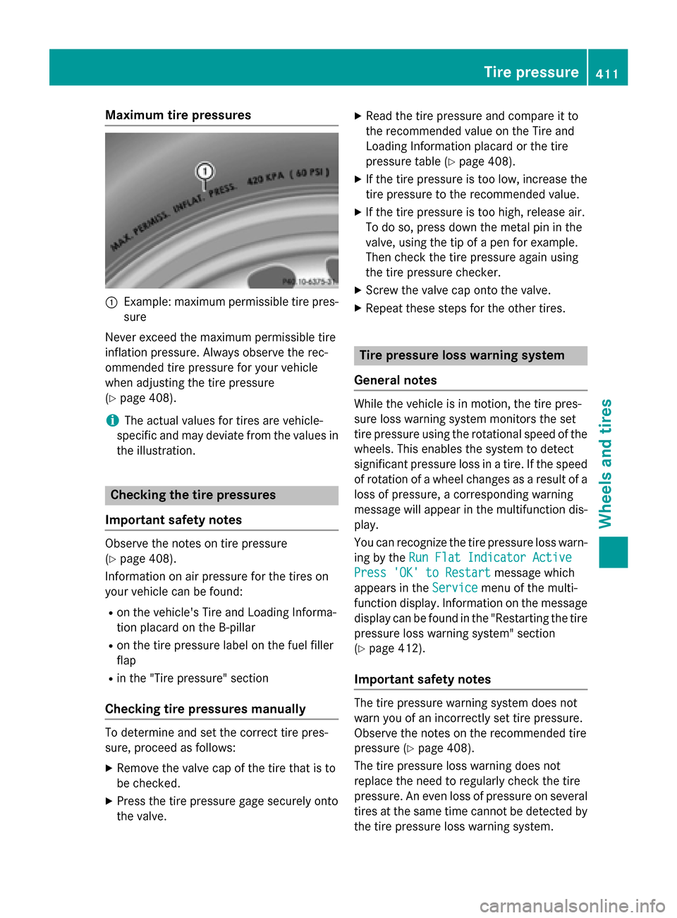
Maximum tire pressures
:Example: maximum permissible tire pres-
sure
Never exceed the maximum permissible tire
inflation pressure. Always observe the rec-
ommended tire pressure for your vehicle
when adjusting the tire pressure
(
Ypage 408).
iThe actual values for tires are vehicle-
specific and may deviate from the values in
the illustration.
Checking the tire pressures
Important safety notes
Observe the notes on tire pressure
(
Ypage 408).
Information on air pressure for the tires on
your vehicle can be found:
Ron the vehicle's Tire and Loading Informa-
tion placard on the B-pillar
Ron the tire pressure label on the fuel filler
flap
Rin the "Tire pressure" section
Checking tire pressures manually
To determine and set the correct tire pres-
sure, proceed as follows:
XRemove the valve cap of the tire that is to
be checked.
XPress the tire pressure gage securely onto
the valve.
XRead the tire pressure and compare it to
the recommended value on the Tire and
Loading Information placard or the tire
pressure table (
Ypage 408).
XIf the tire pressure is too low, increase the
tire pressure to the recommended value.
XIf the tire pressure is too high, release air.
To do so, press down the metal pin in the
valve, using the tip of a pen for example.
Then check the tire pressure again using
the tire pressure checker.
XScrew the valve cap onto the valve.
XRepeat these steps for the other tires.
Tire pressure loss warning system
General notes
While the vehicle is in motion, the tire pres-
sure loss warning system monitors the set
tire pressure using the rotational speed of the
wheels. This enables the system to detect
significant pressure loss in a tire. If the speed
of rotation of a wheel changes as a result of a
loss of pressure, a corresponding warning
message will appear in the multifunction dis-
play.
You can recognize the tire pressure loss warn-
ing by the Run Flat Indicator Active
Press 'OK' to Restartmessage which
appears in the Service
menu of the multi-
function display. Information on the message
display can be found in the "Restarting the tire
pressure loss warning system" section
(
Ypage 412).
Important safety notes
The tire pressure warning system does not
warn you of an incorrectly set tire pressure.
Observe the notes on the recommended tire
pressure (
Ypage 408).
The tire pressure loss warning does not
replace the need to regularly check the tire
pressure. An even loss of pressure on several tires at the same time cannot be detected by
the tire pressure loss warning system.
Tire pressure411
Wheels and tires
Z
Page 427 of 462

DOT (Department of Transportation)
DOT-markedtires fulfill th erequirements of
th e U S Departmen tof Transportation .
Normal occupant weigh t
The number of occupant sfo rwhic hth evehi-
cle is designed multiplie dby 68 kilograms
(15 0lbs) .
Unifor mTire Qualit yGrading Standards
A uniform standard to grade th equalit yof
tires wit hregards to tread quality, tire traction
and temperature characteristics .The qualit y
gradin gassessmen tis made by th emanufac -
turer following specification sfrom th eU.S.
government. The ratings are molded into th e
sidewall of th etire.
Recommended tire pressure s
The recommended tire pressur eapplies to
th etires mounted at th efactory.
The Tir eand Loadin gInformation placard con-
tains th erecommended tire pressures fo r
cold tires on afull yloade dvehicl eand fo rth e
maximum permissibl evehicl espeed.
The tire pressur etable contain sth erecom-
mended pressures fo rcold tires fo rvarious
operating conditions, i.e. differin gload and
speed conditions.
Increased vehicle weigh tdu eto optiona l
equipment
The combine dweight of all standard and
optional equipmen tavailable fo rth evehicle,
regardless of whether it is a
ctually installed
on th evehicl eor not.
Ri m
This is th epart of th ewhee lon whic hth etire
is mounted.
GAW R(Gross Axle Weight Rating)
The GAW Ris th emaximum gross axl eweight
rating. The actual load on an axl emus tnever
exceed th egross axl eweight rating. The
gross axl eweight ratin gcan be found on th e
vehicl eidentification plat eon th eB-pillar on
th edriver's side . Speed rating
The speed ratin
gis part of th etire identifica-
tion .It specifies th espeed range fo rwhic hth e
tire is approved.
GT W(Gross Trailer Weight )
The GTW is th eweight of atrailer includin gth e
weight of th eload, luggage, accessories etc.
on th etrailer .
GV W(Gross Vehicle Weight )
The gross vehicl eweight includes th eweight
of th evehicl eincludin gfuel ,tools ,th espar e
wheel, accessories installed ,occupants, lug-
gage and th edrawbar noseweight ,if applica-
ble. The gross vehicl eweight mus tno texceed
th egross vehicl eweight ratin gGVWR as
specified on th evehicl eidentification plat eon
th eB-pillar on th edriver's side .
GVWR (Gross Vehicle Weight Rating)
The GVWR is th emaximum permissibl egross
weight of afull yloade dvehicl e(the weight of
th evehicl eincl
udin
gall accessories, occu-
pants ,fuel, luggage and th edrawbar nose-
weight ,if applicable). The gross vehicl e
weight ratin gis specified on th evehicl eiden -
tification plat eon th eB-pillar on th edriver's
side .
Maximum loaded vehicle weigh t
The maximum weight is th esum of :
Rthecur bweight of th evehicl e
Rtheweight of th eaccessories
Rth eload limi t
Rtheweight of th efactory installed optional
equipmen t
Kilopascal (kPa)
Metric uni tfo rtire pressure. 6. 9kP acorre-
spond sto 1psi .Another uni tfo rtire pressur e
is bar. 10 0kilopascal s(kPa) are th eequiva-
len tof 1bar.
Load index
In addition to th eload-bearin gindex ,th eload
index may also be imprinte don th esidewall of
All about wheels and tires42 5
Wheels and tires
Z
Page 428 of 462

the tire. This specifies the load-bearing capa-
city more precisely.
Curb weight
The weight of a vehicle with standard equip-
ment including the maximum capacity of fuel,
oil and coolant. It also includes the air-condi-
tioning system and optional equipment if
these are installed in the vehicle, but does not
include passengers or luggage.
Maximum load rating
The maximum load rating is the maximum
permissible weight in kilograms or lbs for
which a tire is approved.
Maximum permissible tire pressure
Maximum permissible tire pressure for one
tire.
Maximum load on one tire
Maximum load on one tire. This is calculated
by dividing the maximum axle load of one axle
by two.
PSI (pounds per square inch)
A standard unit of measure for tire pressure.
Aspect ratio
Relationship between tire height and tire
width in percent.
Tire pressure
This is pressure inside the tire applying an
outward force to each square inch of the tire's surface. The tire pressure is specified in
pounds per square inch (psi), in kilopascal
(kPa) or in bar. The tire pressure should only
be corrected when the tires are cold.
Cold tire pressure
The ti
res are cold:
Rif the vehicle has been parked without
direct sunlight on the tires for at least three
hours and
Rif the vehicle has not been driven further
than 1 mile (1.6 km) Tread
The part of the tire that comes into contact
with the road.
Bead
The tire bead ensures that the tire sits
securely on the wheel. There are several steel
wires in the bead to prevent the tire from
coming loose from the wheel rim.
Sidewall
The part of the tire between the tread and the
bead.
Weight of optional extras
The combined weight of those optional extras
that weigh more than the replaced standard
parts and more than 2.3 kg (5 lbs). These
optional extras, such as high-performance
brakes, level control, a roof rack or a high-
performance battery, are not included in the
curb weight and the weight of the accesso-
ries.
TIN (Tire Identification Number)
This is a unique identifier which can be used
by a tire manufacturer to identify tires, for
example for a product recall, and thus identify
the purchasers. The TIN is made up of the
manufacturer's identity code, tire size, tire
type code and the manufactu ring d
ate.
Load bearing index
The load bearing index (also load index) is a
code that contains the maximum load bearing
capacity of a tire.
Traction
Traction is the result of friction between the
tires and the road surface.
TWR (Tongue Weight Rating)
The TWR specifies the maximum permissible
weight that the ball coupling of the trailer tow hitch can support.
426All about wheels an d tires
Wheels and tires
Page 430 of 462

Mounting a wheel
Preparing the vehicle
XVehicle with emergency spare wheel:
when mounting the emergency spare
wheel in the event of a flat tire, follow the
additional notes on vehicle preparation
under "Flat tire" (
Ypage 387).
XStop the vehicle on solid, non-slippery and
level ground.
XUnload heavy luggage.
XApply the electric parking brake manually.
XBring the front wheels into the straight-
ahead position.
XShift the transmission to position P.
XVehicles with the AIRMATIC package:
make sure that highway level is selected
(
Ypage 219).
XVehicles with the ON&OFFROAD pack-
age:make sure that highway level is selec-
ted (
Ypage 213).
XSwitch off the engine.
XVehicles without KEYLESS-GO: remove
the SmartKey from the ignition lock.
XVehicles with KEYLESS-GO: open the
driver's door.
The on-board electronics now have status
0. This is the same as the SmartKey having
been removed.
XVehicles with KEYLESS-GO: remove the
Start/Stop button from the ignition lock
(
Ypage 165).
XIf included in the vehicle equipment,
remove the tire-change tool kit from the
vehicle.
XSafeguard the vehicle against rolling away.
iApart from certain country-specific varia-
tions, vehicles are not equipped with a tire-
change tool kit. For information on which
tools are required to perform a wheel
change on your vehicle, consult an author-
ized Mercedes-Benz Center. Necessary tire-changing tools can include,
for example:
RJack
RWheel chock
RLug wrench
Securing the vehicle to prevent it from
rolling away
If your vehicle is equipped with a wheel chock,
it can be found in the tire-change tool kit
(
Ypage 386).
The folding wheel chock is an additional
safety measure to prevent the vehicle from
rolling away, for example when changing a
wheel.
XFold both plates upwards :.
XFold out lower plate;.
XGuide the lugs on the lower plate fully into
the openings in base plate =.
XOn level ground:place chocks or other
suitable items under the front and rear of
the wheel that is diagonally opposite the
wheel you wish to change.
428Changing a wheel
Wheels and tires
Page 431 of 462

XOn light downhill gradients:place
chocks or other suitable items in front of
the wheels of the front and rear axle.
Raising the vehicle
GWARNING
If you do not position the jack correctly at the
appropriate jacking point of the vehicle, the
jack could tip over with the vehicle raised.
There is a risk of injury.
Only position the jack at the appropriate jack-
ing point of the vehicle. The base of the jack
must be positioned vertically, directly under
the jacking point of the vehicle.
!AMG vehicles with "Minispare" emer-
gency spare wheel: use the "Minispare"
emergency spare wheel only on the rear
axle. If you mount the "Minispare" emer-
gency spare wheel on the front axle, this
could result in damage to the brake system.
If a tire on the front axle is defective, an
intact wheel from the rear axle must first be
replaced with the "Minispare" emergency
spare wheel. The faulty wheel on the front
axle may only then be replaced by the
undamaged wheel from the rear axle.
Make sure to note the placard on the
"Minispare" emergency spare wheel.
!The jack is designed exclusively for jack-
ing up the vehicle at the jacking points.
Otherwise, your vehicle could be damaged. Observe the following when raising the vehi-
cle:
RTo raise the vehicle, only use the vehicle-
specific jack that has been tested and
approved by Mercedes-Benz. If used incor-
rectly, the jack could tip over with the vehi-
cle raised.
RThe jack is designed only to raise and hold
the vehicle for a short time while a wheel
is being changed. It is not suited for per-
forming maintenance work under the vehi-
cle.
RAvoid changing the wheel on uphill and
downhill slopes.
RBefore raising the vehicle, secure it from
rolling away by applying the parking brake
and inserting wheel chocks. Do not disen-
gage the parking brake while the vehicle is
raised.
RThe jack must be placed on a firm, flat and
non-slip surface. On a loose surface, a
large, flat, load-bearing underlay must be
used. On a slippery surface, a non-slip
underlay must be used, e.g. rubber mats.
RDo not use wooden blocks or similar
objects as a jack underlay. Otherwise, the
jack will not be able t
o achieve its load-
bearing capacity due to the restricted
height.
RMake sure that the distance between the
underside of the tires and the ground does
not exceed 1.2 in (3 cm).
RDo not place your hands or feet under the
raised vehicle.
RDo not lie under the vehicle.
RDo not start the engine when the vehicle is
raised.
RNever open or close a door or the tailgate
when the vehicle is raised.
RMake sure that no persons are present in
the vehicle when the vehicle is raised.
Changing a wheel429
Wheels and tires
Z
Page 433 of 462
Mounting a new wheel
GWARNING
Oiled or greased wheel bolts or damaged
wheel bolts/hub threads can cause the wheel bolts to come loose. As a result, you could
lose a wheel while driving. There is a risk of
accident.
Never oil or grease wheel bolts. In the event of
damage to the threads, contact a qualified
specialist workshop immediately. Have the
damaged wheel bolts or hub threads
replaced/renewed. Do not continue driving.
GWARNING
If you tighten the wheel bolts or wheel nuts
when the vehicle is raised, the jack could tip
over. There is a risk of injury.
Only tighten the wheel bolts or wheel nuts
when the vehicle is on the ground.
!To prevent damage to the paintwork, hold
the wheel securely against the wheel hub
while screwing in the first wheel bolt.
Always pay attention to the instructions and
safety notes in the "Changing a wheel" sec-
tion (
Ypage 427).
Only use wheel bolts that have been designed
for the wheel and the vehicle. For safety rea-
sons, Mercedes-Benz recommends that you
only use wheel bolts which have been
approved for Mercedes-Benz vehicles and the respective wheel.
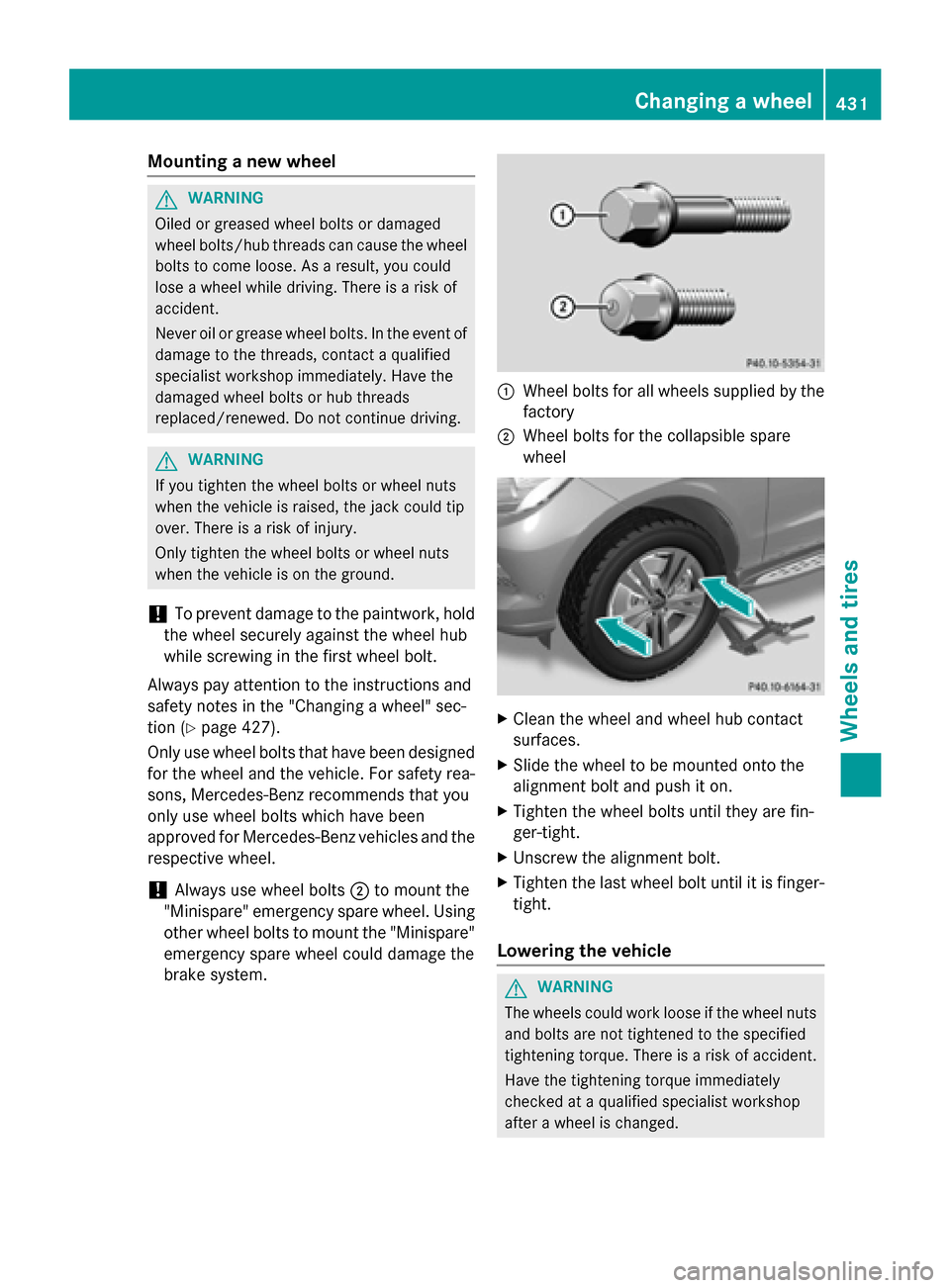
!Always use wheel bolts ;to mount the
"Minispare" emergency spare wheel. Using
other wheel bolts to mount the "Minispare"
emergency spare wheel could damage the
brake system.
:Wheel bolts for all wheels supplied by the
factory
;Wheel bolts for the collapsible spare
wheel
XClean the wheel and wheel hub contact
surfaces.
XSlide the wheel to be mounted onto the
alignment bolt and push it on.
XTighten the wheel bolts until they are fin-
ger-tight.
XUnscrew the alignment bolt.
XTighten the last wheel bolt until it is finger-
tight.
Lowering the vehicle
GWARNING
The wheels could work loose if the wheel nuts and bolts are not tightened to the specified
tightening torque. There is a risk of accident.
Have the tightening torque immediately
checked at a qualified specialist workshop
after a wheel is changed.
Changing a wheel431
Wheels and tires
Z