rear view mirror MERCEDES-BENZ GL SUV 2012 User Guide
[x] Cancel search | Manufacturer: MERCEDES-BENZ, Model Year: 2012, Model line: GL SUV, Model: MERCEDES-BENZ GL SUV 2012Pages: 441, PDF Size: 10.66 MB
Page 227 of 441
R
very close to th erear bumper
R under the rear bumper
R in close range above the handle on the boot
lid
You are alway sresponsible for safety, and
must alway spay attention to you rsurround-
ings when parking and manoeuvring. This
applies to the areas behind, in front of and
beside th evehicle. Yo ucould otherwise
endanger yoursel fand others. G
WARNING
Unde rthe followin gcircumstances, the
reversing camer awill not func tion, or will
function in alimited manner:
R if the boot lid is open
R in heavy rain, snow or fog
R at night or in very dark places
R if the camer aisexposed to very brigh tlight
R if the area is lit by fluorescen tlight or LED
lighting (the display may flicker)
R if there is asudden change in temperature,
e.g. when driving into aheated garage in
winter
R if the camera lens is dirt yorobstructed
R if the rear of your vehicl eisdamaged. In this
event, have the camera positio nand setting
checked at aqualified specialist workshop.
Do not use the reversing camera in these
types of situation. You could otherwis einjure
others or damage object sand your vehicle
whil eyou are parking.
General notes Reversin
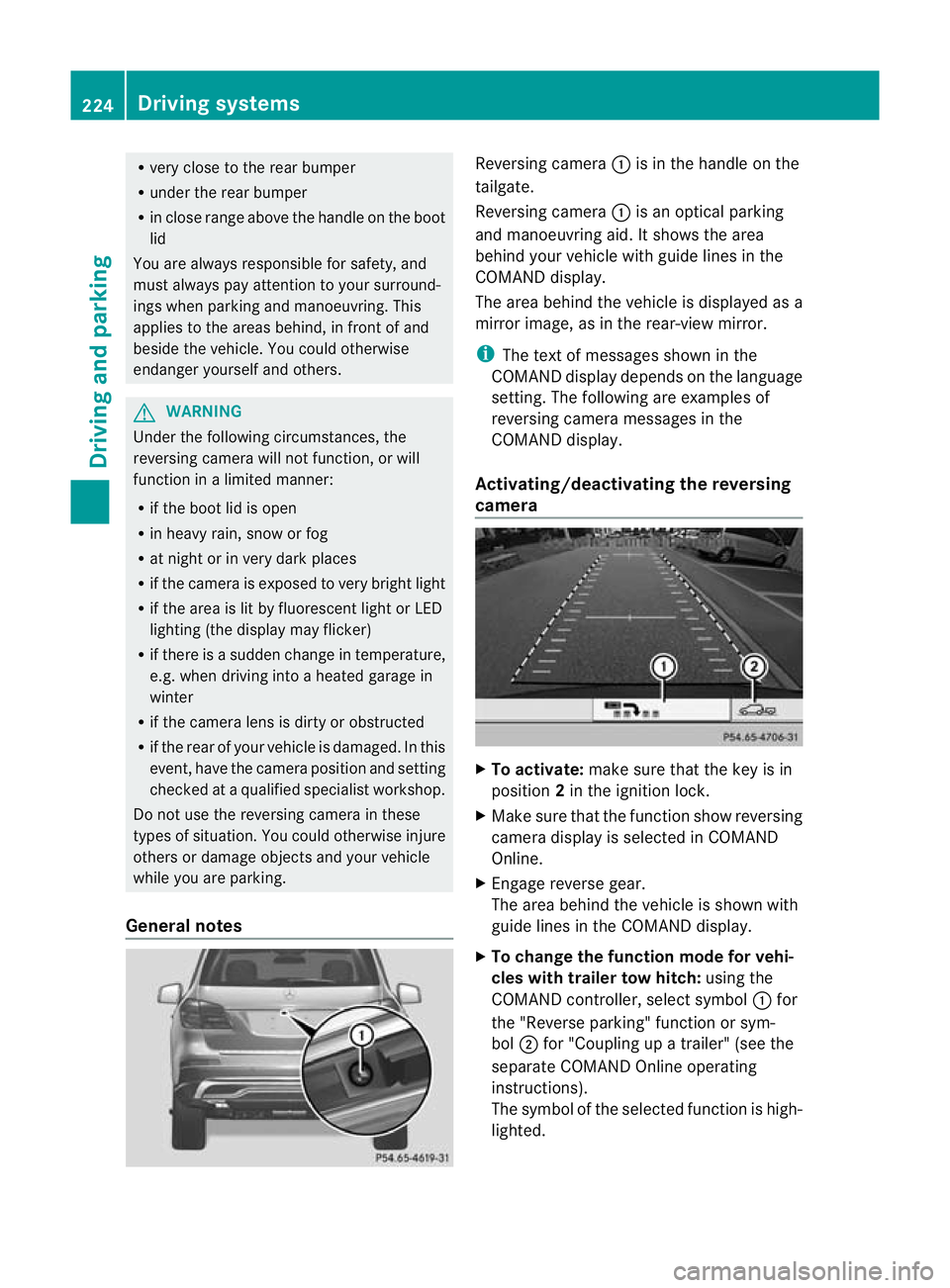
gcamera :is in the handle on the
tailgate.
Reversing camera :is an optical parking
and manoeuvring aid. It shows the area
behind your vehicle with guide lines in the
COMAND displ ay.
Th ea rea behind th evehicle is displayed as a
mirror image, as in the rear-view mirror.
i The text of messages shown in the
COMAN Ddispla ydepends on the language
setting. The following are examples of
reversin gcamera message sint he
COMAN Ddisplay.
Activating/deactivating the reversing
camera X
To activate: make sure that the key is in
position 2in the ignition lock.
X Make sure that the func tion show reversing
camera display is selected in COMAND
Online.
X Engage reverse gear.
The area behind the vehicle is shown with
guide lines in the COMAN Ddisplay.
X To change the function mode for vehi-
cles with trailer tow hitch: using the
COMAND controller, select symbol :for
the "Reverse parking" func tion or sym-
bol ;for "Coupling up atrailer" (see the
separate COMAND Online operating
instructions).
Th es ymbol of the selected function is high-
lighted. 224
Driving systemsDrivin
gand pa rking
Page 231 of 441
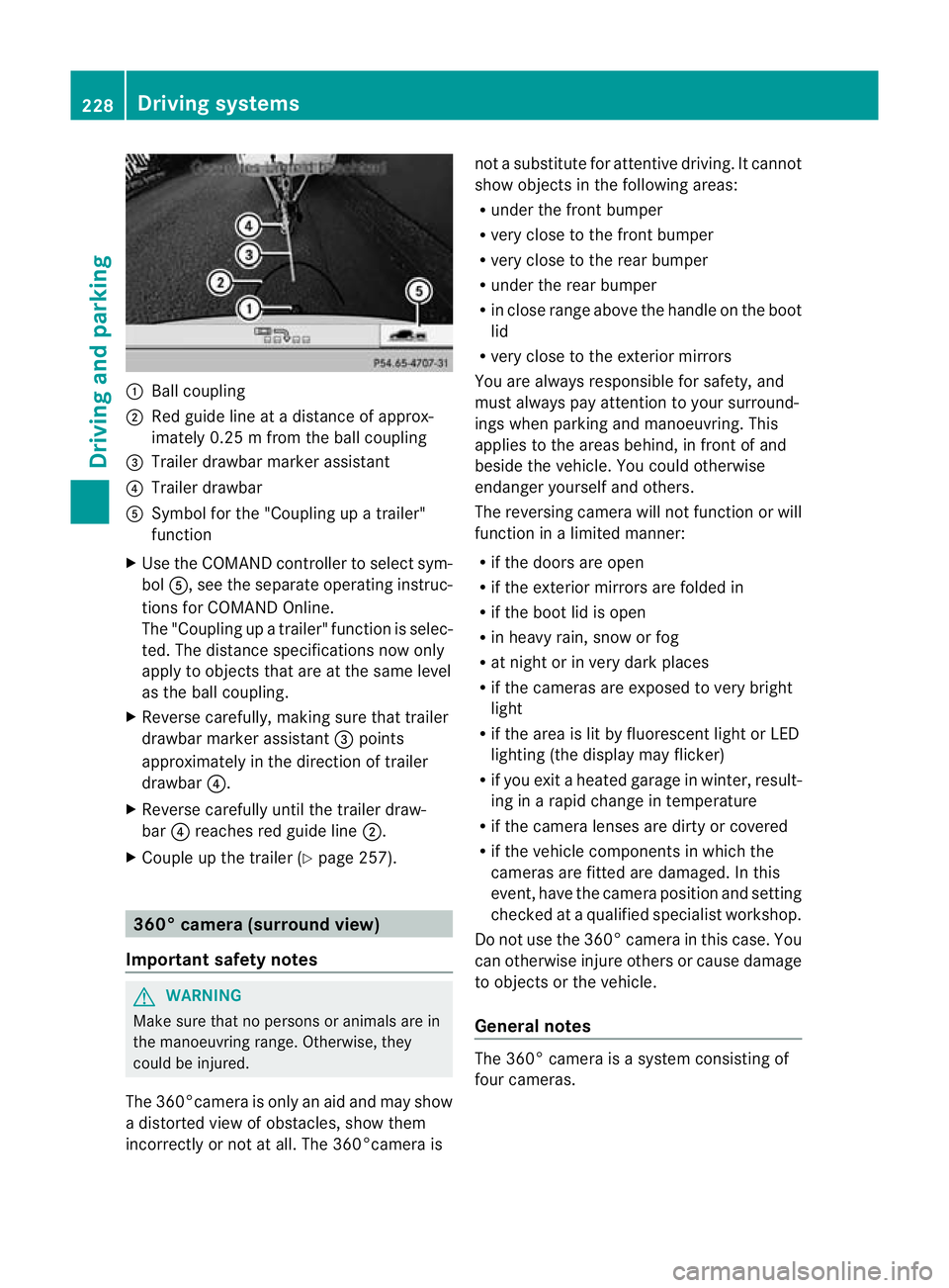
:
Ballcoupling
; Red guid elineatad istance of approx-
imately 0.25 mfromt he ball coupling
= Trailer drawbar marker assistant
? Trailer drawbar
A Symbol for the "Coupling up atrailer"
functi on
X Use th eCOM AND controlle rtoselect sym-
bol A,s ee the separate operating instruc-
tions for COMAN DOnline.
The "Coupling up atrailer" functio nisselec-
ted. The distance specification snow only
apply to objec tsthat are at the same level
as the ball coupling.
X Reverse carefully, making sure that trailer
drawbar marker assistant =points
approximately in the directio noftrailer
drawbar ?.
X Revers ecarefully until the trailer draw-
bar ?reaches red guide line ;.
X Couple up the trailer (Y page 257).360° camera (surround view)
Important safety notes G
WARNING
Make sure that no persons or animals are in
the manoeuvring range. Otherwise, they
could be injured.
The 360°camera is only an aid and may show
ad istorted view of obstacles, show them
incorrectly or not at all. The 360°camer aisnot
asubstitute for attentiv edriving. It cannot
sho wobjects in the following areas:
R under the fr ontb um per
R very clos etothe frontb um per
R very clos etothe rear bumper
R unde rthe rear bumper
R in close range abov ethe handle on th eboot
lid
R ver yclose to th eexter ior mirrors
You are always responsible for safety, and
must always pay attention to your surround-
ing sw hen par king and manoeuvring. This
applies to the areas behind ,inf ront of and
beside th evehicle. Yo ucould otherwise
endanger yoursel fand oth ers.
The rever sing camera will not functi on or will
function in alimited manner:
R if the doors are open
R if the exterior mir rors are folde din
R if the boot lid is open
R in heavy rain, snow or fog
R at night or in very dark places
R if the cameras are exposed to very bright
light
R if the area is lit by fluorescen tlight or LED
lightin g(the display may flicker)
R if you exit aheate dgarage in winter, result-
ing in arapid change in temperature
R if the camera lenses are dirt yorcovered
R if the vehicle component sinwhich the
cam erasare fitted are damaged .Inthis
event, hav ethe cam eraposition and setting
checked at aqualified specialist workshop.
Do not use the 360 °camer aint his case .You
can otherwise injur eothersorc ause damage
to object sorthe vehicle.
Ge neral notes The 360° camera is
asystem consisting of
four cameras. 228
Drivin
gsystemsDriving and parking
Page 232 of 441
The system evaluates images from the fol-
lowin gcameras:
R reversin gcamera
R fron tcamera
R two cameras in the exterior rear view mir-
rors
The cameras capture the immediate sur-
roundings of the vehicle. The system sup-
ports you, e.g. when parking or if vision is
restricted at an exit.
The 360 °camera images can be shown in full
screen mode or in seven different split-screen
views on the COMAND display. Asplit-screen
view also includes atop view of the vehicle.
This view is calculated from the data supplied
by the installed camera s(virtual camera).
Th e7s plit-screen views are:
R top view and picture from the reversing
camera (13 0°viewing angle)
R top view and picture from the fron tcamera
(without displaying the maximum steering
wheel angle)
R top view and enlarged rear view
R top view and enlarged front view
R top view and trailer view (vehicles with
trailer tow hitch)
R top view and pictures from the rearward
facin gmirror cameras (rear wheel view)
R top view and pictures from the forward
facin gmirror cameras (fron twheel view)
i The top vie wand trailer view are available
for vehicles equipped with atrailer tow
hitch.
When th efunction is active and you shift the
transmission from position Dor Rto N,y ou
see the previous view in the COMAN Ddis-
play. The dynamic guidelines are hidden.
When you change between transmission
positions Dand R,you see the previously
selected front or rea rview. Activation conditions The 360
°camera image can be displ ayed if:
R your vehicle is equip pedw ith the 360°
camera.
R COMAND Online is switched on, see the
separate COMAND Online operating
instruc tions.
R the 360° camera func
tion is activated
Activating th e360° camera using the
SYS but ton X
Press and hold the Wbutton for longer
than 2seconds, see the separate COMAND
Online operatin ginstructions.
Depe nding on whether position Dor Ris
engaged, the following is shown:
R full screen display with the image from
the fron tcamera
R full screen display with the image from
the rear camera.
Activating the 360° camer awith
COMAN DOnline X
Press the Wbutton, see the separate
COMAN DOnline operating instructi ons.
X Select System by turning
cVdthe
COMAND contr ollerand press Wto con-
firm.
X Select 360°camera and press
Wto con-
firm.
Depending on whethe rposition Dor Ris
engaged, the following is shown:
R as plit screen with top view and the
image from the front camera or
R as plit screen with top view and the
image from the reversing camera.
For further information about the COMAND
Controller, see the separat eCOMAN DOnline
operating instructions. Drivin
gsystems
229Drivingand pa rking Z
Page 233 of 441
Activating th
e360° camera using
revers egear You can show images from th
e360°c amera
automatically by engagin grevers egear.
X Mak esuret hat the key is in position 2in
th ei gnition lock.
X Mak esuret hat the Activation by R gear setting is ac
tive in COMAND Online,
se et he separa teCOMAND Onlin eoperat-
ing instructions.
X To sho wthe360° camera image: engage
revers egear.
The COMAND display show sthe ar ea
behind th evehicl einS plitS creen:
R vehicl ewithg uide lines
R top vie wofthe vehicle
Selec ting th esplit-screen and full
screen displays X
To switch between split-scree nviews:
switc htot he line with the vehi cles ymbols
by sliding ZVthe COMAND controller.
X Turn cVd the COMAND controlle rand
select one of the vehicle symbols.
X To switch to full scree nmode: select
Full scre en by tur
ning cVd the
COMAN Dcontroller and press Wto con-
firm.
Display sinthe COMAND display Important safety notes
!
Objec tsnot at ground level may appear to
be further away than they actually are, e.g.:
R the bumpe rofaparked vehicle
R the drawbar of atrailer
R theb all coupling of atrailer to whitch
R the rear section of an HGV
R as lanted post
Use the guidelines only for orientation.
Approach object snofurther than the bot-
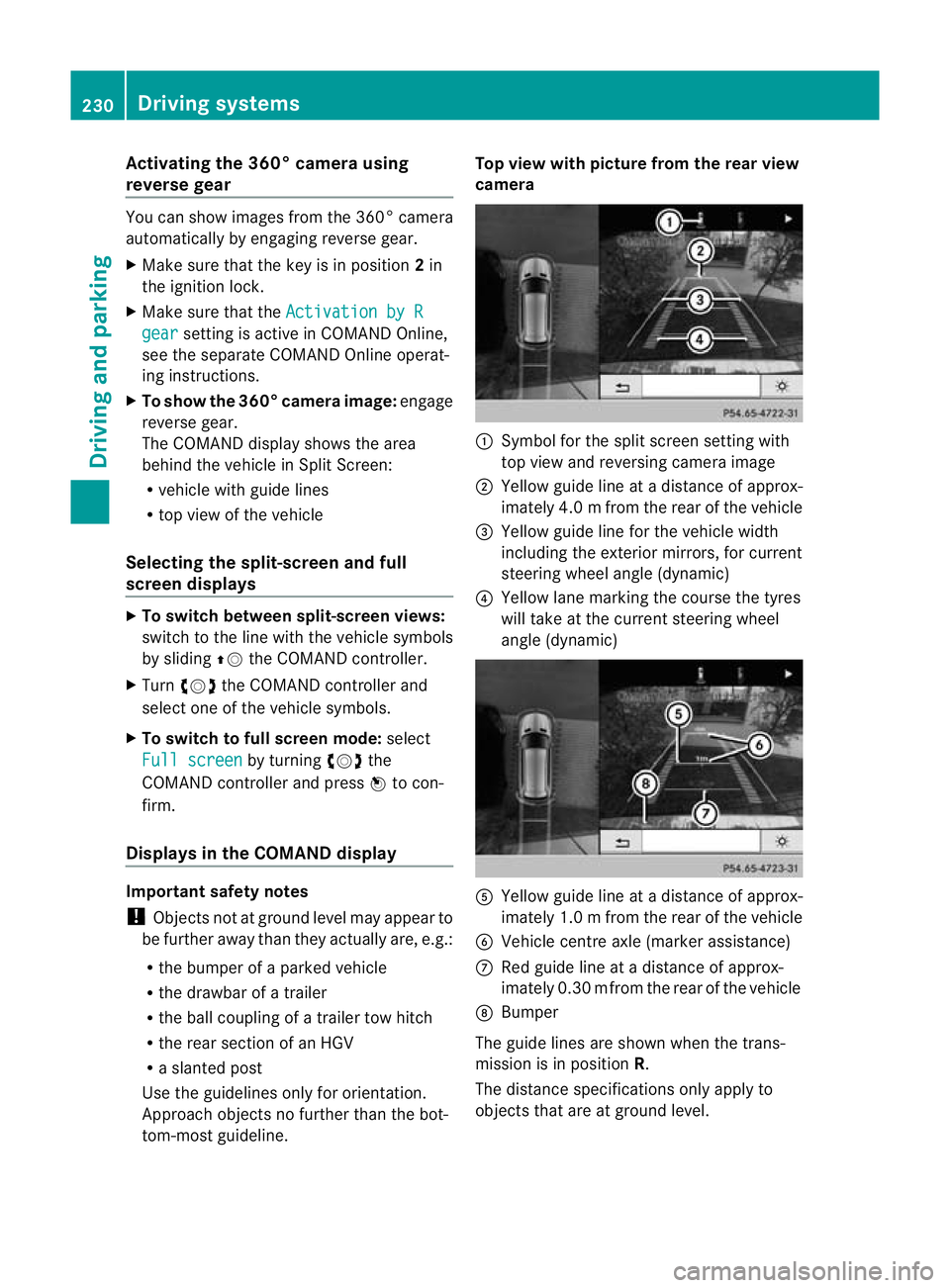
tom-most guidel ine. Top vie
wwith pictu re from the rear view
camera :
Symbol for the split screen settin gwith
top view and reversing camera image
; Yellow guide line at adistance of approx-
imately 4.0 mfrom th erear of the vehic le
= Yellow guide line for the vehicle width
including the exterior mirrors, for current
steering whee langle (dynamic)
? Yellow lane marking the course the tyres
wil ltake at the current steering wheel
angle (dynamic) A
Yellow guide line at adistance of approx-
imately 1.0 mfrom th erear of the vehic le
B Veh icle centr eaxle (marker ass istance)
C Red guide line at adistance of approx-
imately 0.3 0mfrom th erear of the vehic le
D Bumper
Th eg uide lines are sho wn whenthe trans-
mission is in position R.
The distance specifications only apply to
object sthat ar eatground level. 230
Dri
ving systemsDriving and pa rking
Page 234 of 441
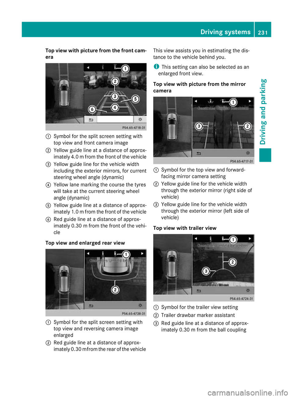
Top view with picture from the fron
tcam-
era :
Symbo lfor the split scr eens etting with
top view and front camera image
; Yellow guid elineatad istance of approx-
imatel y4.0mf rom th efront of th evehicle
= Yellow guid elinef or the vehicle width
inc ludi ng the exterio rmirrors ,for current
steering whee langle (dynamic)
? Yellow lane marking the course the tyres
will take at the current steering wheel
angle (dynamic)
A Yellow guid elineatad istance of approx-
imatel y1.0mf rom th efront of th evehicle
B Redg uide line at adistan ce of approx-
imatel y0.30 mfrom th efront of th evehi-
cle
Top view and enlarged rea rview :
Symbol for the spli tscree nsetting with
top view and reversing camera image
enlarged
; Red guide line at adistanc eofapprox-
imately 0.3 0mfrom th erear of the vehicle This view assists you in estim
ating the dis-
tance to the vehicle behind you.
i This setting can als obeselected as an
enlarged front view.
Top view with picture from th emirror
camera :
Symbo lfor the top view and forward-
facing mirror camera setting
; Yellow guide line for the vehicle width
through the exterior mirror (ri ghts ide of
vehicle)
= Yellow guide line for the vehicle width
through the exterior mirror (left side of
vehicle)
Top vie wwitht railer view :
Symbo lfor the trailer view setting
; Trailer drawbar marker assistant
= Red guide line at adistance of approx-
imately 0.3 0mfrom th eballc oupling Drivin
gsystems
231Drivingand parking Z
Page 350 of 441
You can remove the rubber mat of the cup
holder to clean it. Clean it with clean
,luke-
warm water only.
Temperature-controlled cup holder in
th ef ront-compartment centr econsole G
WARNING
When you use the warmin gfunction ,the metal
insert of thecup holder is heated. Therefore,
do not touch the cup holder inser t.Otherwise,
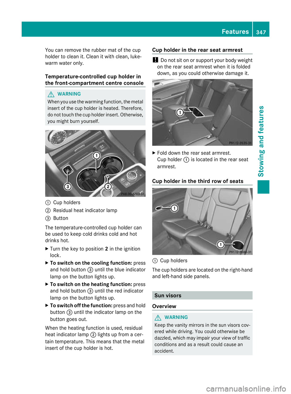
you migh tburny oursel f. :
Cuph olders
; Residual heat indicator lamp
= Button
Th et emperature-c ontrolle dcup holde rcan
be used to keep cold drinks cold and hot
drinks hot.
X Turn the key to position 2in the ignition
lock.
X To switch on th ecooling function: press
and hold button =until th eblue indicator
lamp on th ebutton lights up.
X To switch on th eheating function: press
and hold button =until the red indicator
lamp on the button lights up.
X To switch off th efunc tion: press and hold
button =until the indicator lamp on the
button goes out.
When the heatin gfunction is used, residual
heat indicator lamp ;lights up fro macer-
tain temperature. This mean sthat the metal
insert of the cup holder is hot. Cu
ph older in th erears eat armrest !
Do not sit on or support your body weight
on the rear seat arm rest when it is folded
down ,asy ou coul dotherwise damage it. X
Fold down the rear seat armrest.
Cup holder :is located in the rear seat
armrest.
Cup holder in th ethird row of seats :
Cup holders
The cup holders are located on the right-hand
and left-han dside panels. Sun visors
Overview G
WAR
NING
Keep the vanity mirrors in the sun visors cov-
ered whil edriving.Y ou coul dotherwise be
dazzled, which may impair your view of traffic
conditions and as aresult could cause an
accident. Features
347Stowing and features Z
Page 355 of 441
i
On some mobile phone brackets, you first
hav etoc onnect the mobile phone via Blue-
tooth ®
to the mobile phone bracke t(see
the separate operating instructions for the
mobile phone bracket).
If this is the case, the mobile phone does
not hav etobei nsertedinto the bracket for
you to be able to use the telephone func-
tions .However, the charging function and
aerial function ar enot available.
Operating th emobile phone You can operate the telephone using the
6
and~ buttons on the multifunction
steering wheel. You can operate other mobile
phone functions via the on-board computer
(Y page 275).
When you remov ethe key from the ignition
lock ,the mobile phone stay sswitched on.
However, you can no longer use the hands-
free system.
If you have an active call and woul dlike to
take the key out of the ignition lock, first
remov ethe mobile phone from the bracket.
i When usin gabracke tconnected to the
mobile phone via Bluetooth ®
and you wish
to proceed with acall:
Switch to private mode before removing
the key from the ignition lock. Otherwise, it
may take up to 20 seconds before the
mobile phone separates from the system.
Only then can the telephone call continue.
Information on the necessary steps for set-
ting up "private mode" can be found in the
separate mobile phone operating instruc-
tions.
i Not all mobile phones support "private
mode". Garage door opener
Important safety notes The HomeLink
®
garage door opener integra-
ted in the rear-view mirror allows you to oper-
ate up to three different door and gate sys-
tems.
i The garage door opener is only available
for certain countries. Observe the legal
requirements for each individual country.
The HomeLink ®
garage door opener is
compatible with most European garage and
gate opener drives. More information on
HomeLink ®
and/or compatible products is
available from:
R at aq ualified specialised workshop
R the HomeLink ®
hotline
(0) 08000 466 354 65 (free of charge) or
+49 (0) 683 8907 277 (charge sapply)
R on the Internet at:
http://www.homelink.com
Progra mming Programming buttons
G
WARNING
Only press the button on the integrated
garage door opener if there are no persons or
object spresent withi nthe sweep of the
garage door. Person scould otherwise be
injure dasthe door moves. Integrated garage door opene
rinthe rear-view mir-
ror 352
FeaturesStowin
gand features
Page 356 of 441
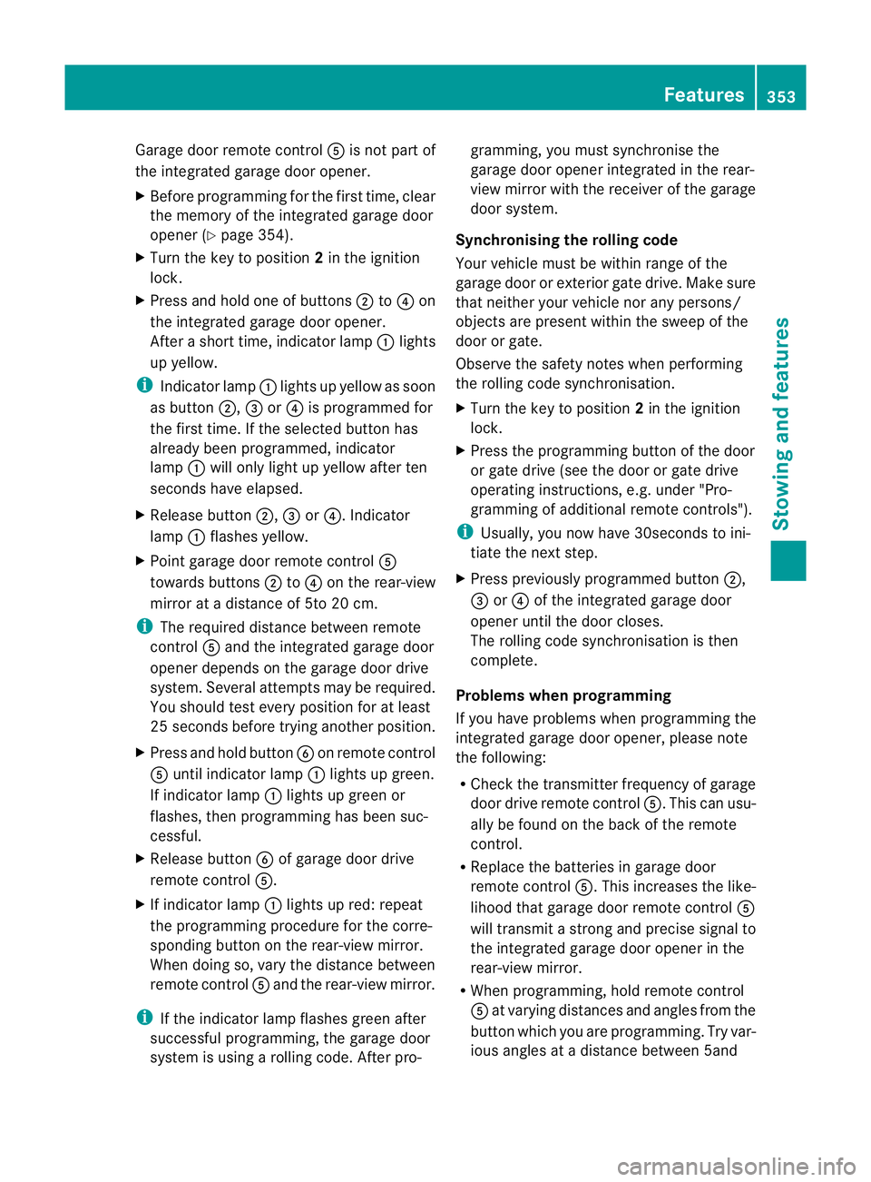
Garage door remote con
trol A is no tpart of
the integrated garage door opener.
X Before programmin gfor th efirst time, clear
th em emory of th eintegrated garage door
ope ner(Ypage 354).
X Turn th ekey to position 2in th eignition
lock.
X Press and hold on eofbuttons ;to? on
the integrate dgarag edoor opener.
Afte ras hort time, indicator lamp :lights
up yellow.
i Indicator lamp :lights up yellow as soon
as button ;,=or? is programmed for
the first time. If the selected button has
already been programmed ,indicator
lamp :will only light up yellow after ten
seconds have elapsed.
X Rele asebutton ;,=or?.I ndicator
lamp :flashes yellow.
X Point garage doo rremote control A
towards buttons ;to? on the rear-view
mirror at adistance of 5to 20 cm.
i The required distance between remote
control Aand the integrated garage door
opener depends on the garage door drive
system. Several attempt smay be required.
You should test every position for at least
25 seconds before trying another position.
X Press and hold button Bon remote control
A until indicator lamp :lights up green.
If indicator lamp :lights up green or
flashes ,then programming has been suc-
cessful.
X Release button Bof garage door drive
remote con trolA.
X Ifindicator lamp :lights up red: repeat
the programming procedur efor the corre-
spondin gbutton on the rear-view mirror.
When doing so, vary the distance between
remote control Aand the rear-view mirror.
i If the indicator lamp flashes green after
successful programming, the garage door
system is using arollin gcode. Af terp ro- gramming
,you must synchronise the
garage door opener integrated in the rear-
view mirror with the receive rofthe garage
door system.
Synchronising th erolling code
Your vehicle must be within range of the
garage door or exterior gate drive. Make sure
that neither your vehicle nor any persons/
objects are present within the sweep of the
door or gate.
Observe the safety notes when performing
the rolling code synchronisation.
X Turn the key to position 2in the ignition
lock.
X Press the programming button of the door
or gate drive (see the door or gate drive
operating instructions, e.g. under "Pro-
gramming of additional remote controls").
i Usually, you now have 30seconds to ini-
tiate the next step.
X Press previousl yprogramme dbutton ;,
= or? of the integrated garage door
opener until the door closes.
The rolling code synchronisatio nist hen
complete.
Problems when progra mming
If you have problems when programming the
integrated garage door opener, please note
the following:
R Check the transmitter frequency of garage
door driv eremote control A.This can usu-
ally be found on the bac kofthe remote
con trol.
R Replace the batteries in garage door
remote control A.This increases the like-
lihood that garage door remote con trolA
will transmit astron gand precis esignal to
the integrated garage door opener in the
rear-view mirror.
R When programming, hold remote control
A at varying distances and angles from the
button which you are programming. Try var-
ious angles at adistance between 5and Features
353Stowingand features Z