height MERCEDES-BENZ GL SUV 2012 Owners Manual
[x] Cancel search | Manufacturer: MERCEDES-BENZ, Model Year: 2012, Model line: GL SUV, Model: MERCEDES-BENZ GL SUV 2012Pages: 441, PDF Size: 10.66 MB
Page 50 of 441
R
Persons under 1. 50mtall cannot wear the
seat belts correctly. For this reason secure
person sless than 1.50 mtall in specially
designed, suitable restraint systems.
R Children under 1. 50mt all and younger
than twelv eyears of age canno twear the
seat belts cor rectly. For thi sreason secure
them in special suitable child restraint sys-
tems installed on asuitable seat. Additional
information can be found in the Operating
Instructions in the chapter "Safety", "Chil-
dren in the Vehicle". Observe the installa-
tion instructions of the child restraint sys-
tem manufac turer.
R Do not secure an object wit haseat belt if
the seat belt is also being used by one of
the vehicle's occupants. G
WAR
NING
The seat belt doe snot offer the intended level
of protection unless the back rest is almost
ver tical. Under certain circumstances, this
coul dcause severe or even fatal injuries in the
event of an accident.
Befor estarting ajourney, mak esure that the
seat is properly adjusted and that the back-
rest is almost vertical. G
WARNING
Ad irtyo rdamaged seat belt or one that has
been modified or subjected to aload in an
accident no longer offers the intended level of
protection. Un dercertain cir cumstances, this
could caus esever eoreven fatal injurie sinthe
even tofana ccident.
For thi sreason ,chec kregularly that the seat
belts are not damaged or dirty.
Alway shave damaged seat belts or seat belts
that have been subjected to aload in an acci-
dent replaced at aqualified specialist work-
shop.
For safety reasons, Mercedes -Benz recom-
mends that you only use seat belts which have
been approved by Mercedes-Benz for your
vehicle. Seat belts are the most effectiv
emeans of
restraining the movemen tofvehicle occu-
pant sint he even tofanaccident. This
reduce sthe risk of vehicle occupan tscoming
into contact with parts of the vehicle interior.
Fastenin gseat belts X
Adjust the seat and move the backrest to
an almost vertical position (Y page 100).
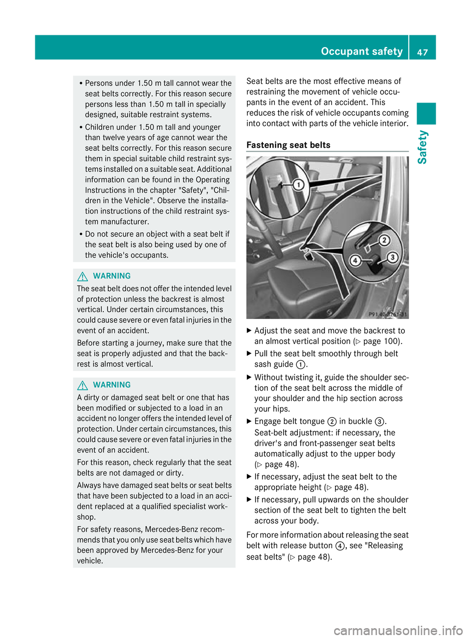
X Pull the seat belt smoothly through belt
sash guide :.
X Without twistin git, guid ethe shoulder sec-
tion of the seat belt across the middle of
your shoulder and the hip section across
your hips.
X Engage belt tongue ;in buckle =.
Seat-belt adjustment :ifnecessary, the
driver' sand front-passenger sea tbelts
automatically adjust to the upper body
(Y page 48).
X If necessary, adjust the seat belt to the
appropriate height (Y page 48).
X If necessary, pull upwards on the shoulder
section of the seat belt to tighten the belt
across your body.
For mor einformation about releasing the seat
bel tw ith release button ?,see "Releasing
seat belts" (Y page 48). Occupant safety
47Safety Z
Page 51 of 441
Sea
tbelt adjustment The seat-belt adjustment func
tion adjusts the
driver's and front-passenger seat belt to the
upper body of the occupants.
The belt strap is tighte neds lightly when:
R you engage the belt tongue in the belt
buckle and you then turn the key to position
2in the ignition lock.
R the key is in position 2in the ignition lock
and you then engage the belt tongue in the
buckle.
The seat-belt adjustment will apply acertain
tightening force if any slack is detected
between the occupant and the seat belt. Do
not hold on to the seat belt tightly while it is
adjusting. You can switch the seat-belt
adjustmen tonand off in the on-board com-
puter (Y page285).
Th es eat-belt adjustmen tisani ntegral part of
the PRE-SAFE ®
convenience function. More
information abou tPRE-SAFE ®
can be found
under "PRE-SAFE ®
(preventative occupant
protection)" (Y page 45).
Belt height adjustment You can adjust the belt height for the front
seats
.Adjust the belt to aheight that allows
the upper part of the seat belt to be routed
across the centre of your shoulder.
X To raise: slide the belt sash guide upwards.
The belt sash guide engages in various posi-
tions.
X To lower: press and hold belt sash guide
release :. X
Slide the belt sash guide downwards.
X Let go of belt sash guide release :and
mak esure that the belt sash guide has
engaged.
Releasing the seat belts !
Make sure that the seat belt is fully rolled
up. Otherwise, the seat belt or belt tongue
will be trapped in the door or in the seat
mechanism. This could damage the door,
the door trim panel and the seat belt. Dam-
aged seat belts can no longer fulfil their
protective function and must be replaced.
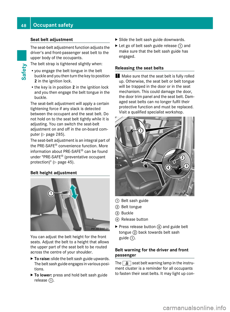
Visit aqualified specialist workshop. :
Belt sash guide
; Belt tongue
= Buckle
? Release button
X Press release button ?and guide belt
tongue ;back towards belt sash
guide :.
Belt warning for the driver and front
passenger The
7 seat belt warning lamp in the instru-
ment cluster is areminder for all occupants
to fasten their seat belts. It may light up con- 48
Occupant safetySafety
Page 104 of 441

Seats
Important safety notes
G
WARNING
The seat scan still be adjusted when there is
no key in the ignition lock. For this reason,
children shoul dnever be left unsupervised in
the vehicle. They could adjust the seats and
becom etrapped. G
WARNING
Only adjus tthe driver's seat when the vehicle
is stationary .You will otherwise be distracted
from the road and traffic condition sand you
could los econtrol of the vehicle as aresult of
the seat moving. This could cause an acci-
dent. G
WARNING
If you adjust the seat height carelessly, you or
others could be trapped and thereby injured.
Children in particula rcould unintentionally
press the buttons to electrically adjust the
seats and becom etrapped.
Take care that:
R while moving th eseats, your hands do not
get under the lever assembly of the seat
adjustmen tsystem.
R children in the vehicle do not slid etheir
hands unde rthe levers. G
WARNING
Make sur ethat nobody can becom etrapped
when adjustin gthe seats.
Observ ethe note sonairbags.
Secur echildren as recommended; see the
"Childre ninthe vehicle" section. G
WARNING
Make sur ethat the bac kofyour head is sup-
ported at eye level by the cen tralarea of the
head restraint. If your head is not supported
correctly by th ehead restraint ,you coul dsuf-
fer asever eneck injury in the event of an accident
.Never driv eifthe head rest raints are
not engaged and set correctly. G
WARNING
As eat belt can only offer its intended degree
of protection when the back rest is almost ver-
tical and the occupan tiss itting upright. Avoid
seat positions that do not allow the seat belt
to be routed correctly. Adjust the backrest so
that it is as upright as possible .Never travel
with the back rest reclined too fa rbackwards.
You could otherwise be seriousl yoreven
fatally injured in th eevent of an accident or
sudden braking.
! To avoid damag etothe seats and the seat
heating, observe the followin ginformation:
R do not spill any liquids on the seats. If
liquid is spilled on the seats, dry them as
soon as possible.
R if the sea tcover sare damp or wet, do not
switc hont he seat heating. The seat
heating should also not be used to dry
the seats.
R clea nthe seat cover sasrecommended;
see "In terior care".
R do not transport heav yloads on the
seats. Do not plac eshar pobjects on the
seat cushions ,e.g. knives, nails or tools.
Th es eats should only be occupied by
passengers, if possible.
R when the seat heatin gisinoperation ,do
not cover the seats with insulating mate-
rials, e.g. blanke ts,c oats, bags, seat cov-
ers, child seats or booster seats.
! Make sure that ther eare no objects in the
footwell or behind th eseats when moving
the seat back .There is arisk that the seats
and/or the objects could be damaged.
i The head restraint scannot be removed
from the fron tseats. The rear-compart-
men thead restraints, however ,can be
removed (Y page 104).
For more information ,contac taqualified
specialist workshop. Seats
101Seats, steering wheel and mirrors Z
Page 105 of 441
i
Further related subjects:
R Luggage compartment enlargement
(folding do wnthe rear bench seat)
(Y page 341) Adjustin
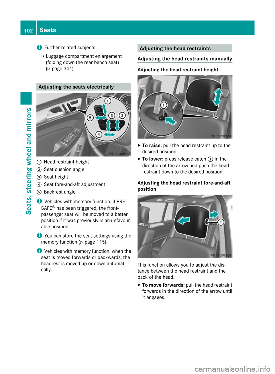
gthe seats electrically :
Hea drestraint height
; Seat cushion angle
= Seat height
? Seat fore-and-aft adjustment
A Backrest angle
i Vehicles with memory function: if PRE-
SAFE ®
has been triggered, the front-
passenger seat will be moved to abetter
position if it was previously in an unfavour-
able position.
i You can store the seat settings using the
memory function (Y page 115).
i Vehicles with memory function: when the
seat is moved forwards or backwards, the
headrest is moved up or down automati-
cally. Adjusting the hea
drestraints
Adjusting the head restraints manually Adjusting the head restraint height
X
To raise: pull the head restrain tuptot he
desired position.
X To lower: press release catch :in the
direction of the arrow and push the head
restraint down to the desired position.
Adjusting th ehead restraint fore-and-aft
position This func
tion allows you to adjust the dis-
tance between the head restraint and the
back of the head.
X To move forwards: pull the head restraint
forwards in the direction of the arrow until
it engages. 102
SeatsSeats, steering wheel and mirrors
Page 106 of 441

There are
anumber of detents.
X To move backwards: press and hold
release button :and push the head
restraint backwards.
X When the head restraint is in the desired
position, release the button and make sure
that the head restraint is engage dinposi-
tion.
Adjusting th ehead restraints electri-
cally X
To adjust the head restraint height: slide
the switch for head restraint adjustment
(Y page 102 )upordown in the direction of
the arrow.
Adjusting th eluxury head restraints Th
e1 st row of seat shas luxury head
restraints.
X To adjust the side bolsters of the head
restraint: push or pull right and/or left-
hand side bolster :into the desired posi-
tion.
X To adjust the fore-and-af tposition of
the head restraint: push or pull the head
restraint in the direction of arrow ;.Rear seat head restraints Adjusting the rear seat head restraint
height
X
Onc ethe head rest raint is fully lowered,
press release catch :.
X To raise: pull the head restraint up to the
desired position.
X To lower: press release catch :and push
the head restraint down until it is in the
desired position.
Adjusting the rear seat hea drestraint
angle Adjust the head restraints so that they are as
close as possible to your head.
You can only adjust the two outer head
restraints.
X
Using both hands, reach back and grasp
the sides of the head restraint.
X Pull the lower edge of the head restraint
forwards or back until it is in the desired
position. Seats
103Seats, steering wheel and mirrors Z
Page 113 of 441
Problems wit
hthe seat ventilation Th
es eat ven tilation has switched off prema-
turely or cannot be switched on. The vehicle's
electrical system voltage is too low because
too many electrical consumer sare switched
on.
X Switch off electrica lconsumers that you do
not need, such as the rea rwindow heating
or interior lighting. Steering wheel
Important safet
ynotes G
WARNING
Do not adjust the steering wheel while driving.
Adjusting the steering wheel while driving, or
drivin gwithout the steering wheel adjustment
featur elocked coul dcause the driver to lose
control of the vehicle.
The electrical steering wheel adjustment fea-
ture can be operated at any time. Therefore,
do not leave children unattended in the vehi-
cle, or with access to an unlocked vehicle. A
child's unsupervised access to avehicle could
result in an accident and/or serious personal
injury. Adjusting the steering whee
lman-
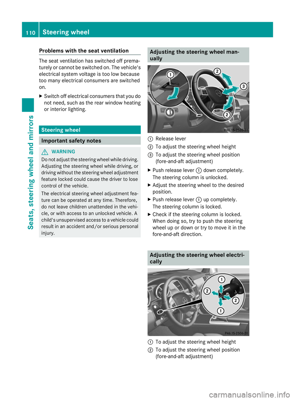
ually :
Release lever
; To adjus tthe steering wheel height
= To adjust the steering wheel position
(fore-and-af tadjustment)
X Push release lever :down completely.
The steerin gcolum nisu nlocked.
X Adjus tthe steering wheel to the desired
position.
X Push release lever :up completely.
The steering column is locked.
X Chec kifthe steering column is locked.
When doing so, tr ytopush the steering
wheel up or down or try to move it in the
fore-and-aft direction. Adjusting the steering wheel electri-
cally :
To adjust the steering wheel height
; To adjust the steering wheel position
(fore-and-aft adjustment) 110
Steering wheelSeats, steerin
gwhee land mirrors
Page 230 of 441
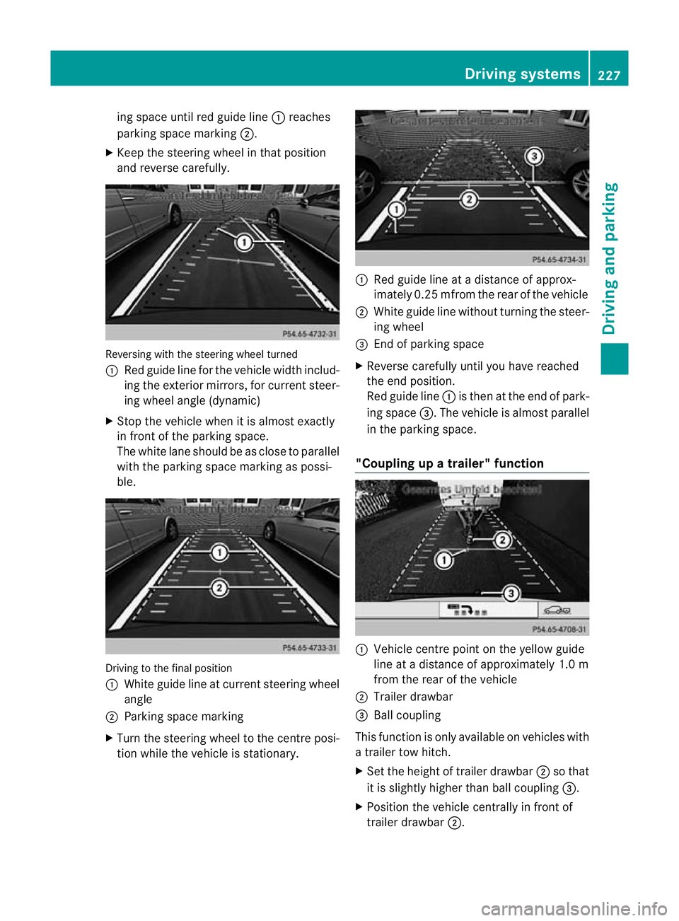
ing space until red guide line
:reaches
parking space mar king ;.
X Keep the steering wheel in that position
and reverse carefully. Reversing with the steerin
gwheel turned
: Red guide line for the vehicle width includ-
ing the exterior mir rors, for current steer-
ing whee langle (dynamic)
X Stop the vehicle whe nitisalmost exactly
in fron tofthe par king space.
The whit elane should be as close to parallel
with the parking space marking as possi-
ble. Drivin
gtothe final position
: Whit eguide line at current steerin gwheel
angle
; Parking space marking
X Turn the steering wheel to the centr eposi-
tion while the vehicle is stationary. :
Red guide line at adistanc eofapprox-
imately 0.2 5mfrom th erear of the vehicle
; White guide line without turning the steer-
ing wheel
= End of park ings pace
X Reverse carefully unti lyou have reached
the end position.
Red guide line :is then at the end of park-
ing space =.The vehicle is almost parallel
in the parkin gspace.
"Coupling up atrailer" function :
Vehicle centre point on the yellow guide
line at adistance of approximately 1.0 m
from the rear of the vehicle
; Trailer drawbar
= Ball coupling
This func tion is only available on vehicles with
at railer to whitch.
X Set the height of trailer drawbar ;so that
it is slightly higher than ball coupling =.
X Position the vehicle centrally in front of
trailer drawbar ;. Drivin
gsystems
227Drivingand pa rking Z
Page 409 of 441
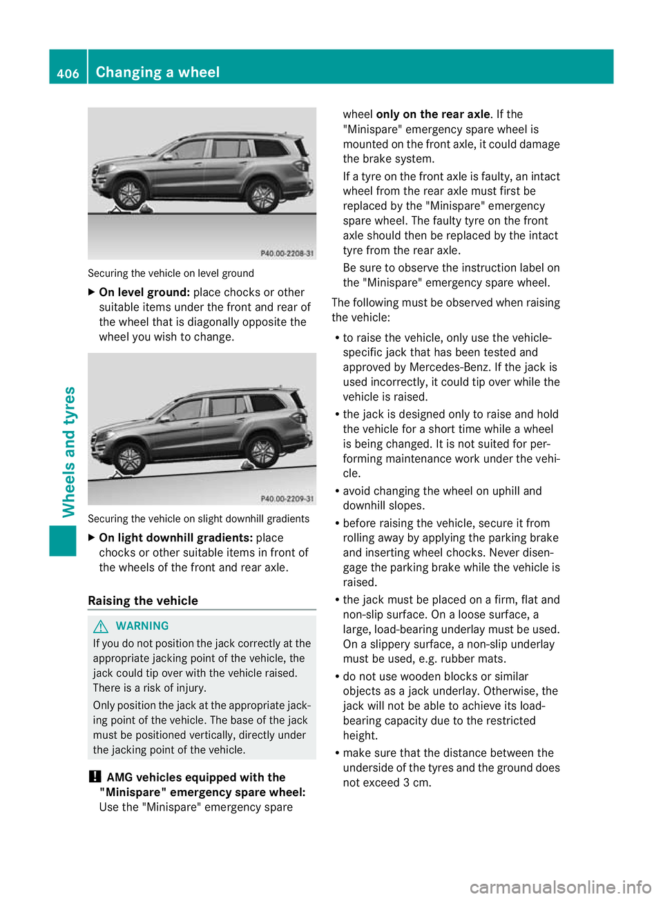
Securing the vehicle on level ground
X
On level ground: place chocks or oth er
su itabl eitem sunder the front and rea rof
the whee lthat is diagonally opposite the
whee lyou wish to change. Securing the vehicle on slight downhill gradients
X On ligh tdownhill gradients: place
chocks or other suitabl eitems in front of
the wheels of the front and rear axle.
Raisin gthe vehicle G
WARNING
If you do not positio nthe jac kcorrectly at the
appropriate jackin gpoint of the vehicle, the
jac kc ould tip over with the vehicle raised.
There is arisk of injury.
Only position the jack at the appropriate jack-
ing point of the vehicle. The base of the jack
must be positioned vertically, directly under
the jackin gpoint of the vehicle.
! AMG vehicles equipped with the
"Minispare" emergency spare wheel:
Use the "Minispare" emergency spare wheel
only on th erear axle.Ift he
"Minispare" emergenc yspare wheel is
mounted on the front axle, it could damage
the brak esystem.
If at yre on the front axle is faulty, an intact
whee lfrom th erear axle must first be
replaced by the "Minispare" emergency
spare wheel. The faulty tyr eonthe front
axl es hould then be replaced by the intact
tyr efrom th erear axle.
Be sure to observ ethe instruction label on
the "Minispare" emergenc yspare wheel.
The following must be observed when raising
the vehicle:
R to raise the vehicle, only use the vehicle-
specifi cjack that has been tested and
approved by Mercedes-Benz .Ifthe jac kis
used incorrectly, it could tip over while the
vehicle is raised.
R the jack is designed only to raise and hold
the vehicle for ashort tim ewhile awheel
is being changed. It is not suited for per-
forming maintenance wor kunder the vehi-
cle.
R avoid changing the wheel on uphil land
downhil lslopes.
R before raising the vehicle, secure it from
rolling away by applying the parkin gbrake
and inserting whee lchocks. Never disen-
gage the parkin gbrake whil ethe vehicle is
raised.
R the jac kmust be placed on afirm ,flat and
non-slip surface. On aloose surface, a
large, load-bearing underlay must be used.
On aslippery surface, anon-slip underlay
must be used, e.g. rubber mats.
R do not use wooden block sorsimilar
objects as ajack underlay .Otherwi se,the
jack wil lnot be able to achiev eits load-
bearing capacity due to the restricted
height.
R mak esure that the distanc ebetween the
underside of the tyr es andthe grou nddoes
not exceed 3cm. 406
Changing
awheelWheels and tyres
Page 434 of 441
Vehicl
edata General notes
Please not ethat for the specified vehicle
data:
R the heights specified may vary as aresult
of:
- tyres
- load
- condition of the suspension
- optiona lequipment
R item sofo ptional equipmen tincrease the
unlade nweight and reduc ethe maximum
payload. The unladen weight is specifie din
accordanc ewith EC directiv eand includes:
- driver (68 kg)
- luggage (7 kg)
- all fluids (fuel tank 90% full)
R vehicle-specific weight information can be
found on the vehicl eidentification plate
(Y page 422).
R only for cer tain countries: you can find vehi-
cle-specific vehicle data in the COC docu-
ment s(CERTIFICATE OF CONFORMITY).
Thes edocument sare delivere dwith your
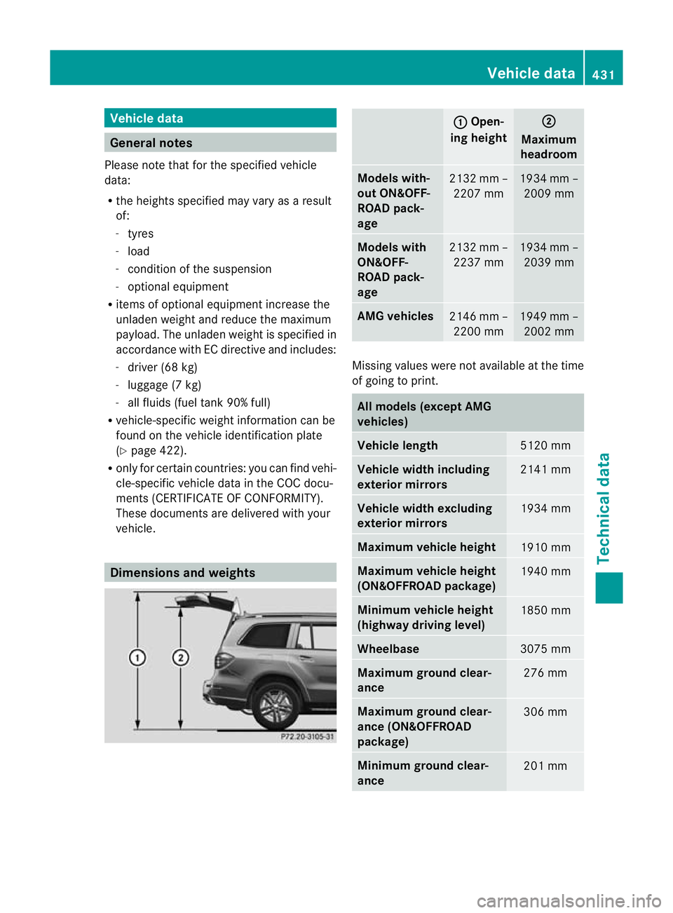
vehicle. Dimensions and weights : Open-
ing height ;
Maximum
headroom Models with-
out ON&OFF-
ROAD pack-
age
213
2mm–
2207 mm 1934 mm –
2009 mm Model
swith
ON&OFF-
ROAD pack-
age 2132 mm –
2237 mm 1934 mm –
2039 mm AMG vehicles
2146 mm –
2200 mm 1949 mm –
2002 mm Missing values were not available at the time
of going to print.
All models (except AMG
vehicles)
Vehicle length
5120 mm
Vehicle width including
exterior mirrors
2141 mm
Vehicle width excluding
exterior mirrors
1934 mm
Maximu
mvehicle height 1910 mm
Maximu
mvehicle height
(ON&OFFROAD package) 1940 mm
Minimum vehicle height
(highway driving level)
1850 mm
Wheelbase
3075 mm
Maximu
mground clear-
ance 27
6mm Maximum gro
undc lear-
ance (ON&OFFROAD
packa ge) 306 mm
Mi
nimum ground clea r-
ance 20
1mm Vehicl
edata
431Technical data Z
Page 435 of 441
All models (except AMG
vehicles)
Unladen weight
Maximum roof load
10
0kg GL 63 AMG
Vehi
clel ength 514
6mm Vehicle width including
exterio rmirrors 2141 mm
Vehicle width excluding
exterior mirrors
1982 mm
Maximum vehicle height
1903 mm
Minimum vehicle height
1850 mm
Wheelbase
3075 mm
Maximum ground clear-
ance
24
9mm Min
imum ground clear-
ance 198 mm
Un
laden weight 2580 kg
Maximum roof load
100 kg
Traile
rtow hitch Mounting dimensions
! If you have atrailer to whitch retrofitted,
changes to the cooling system and drive
train may be necessary, depending on the
vehicle type.
If you have atrailer to whitch retrofitted,
observ ethe anchorage point sonthe chas-
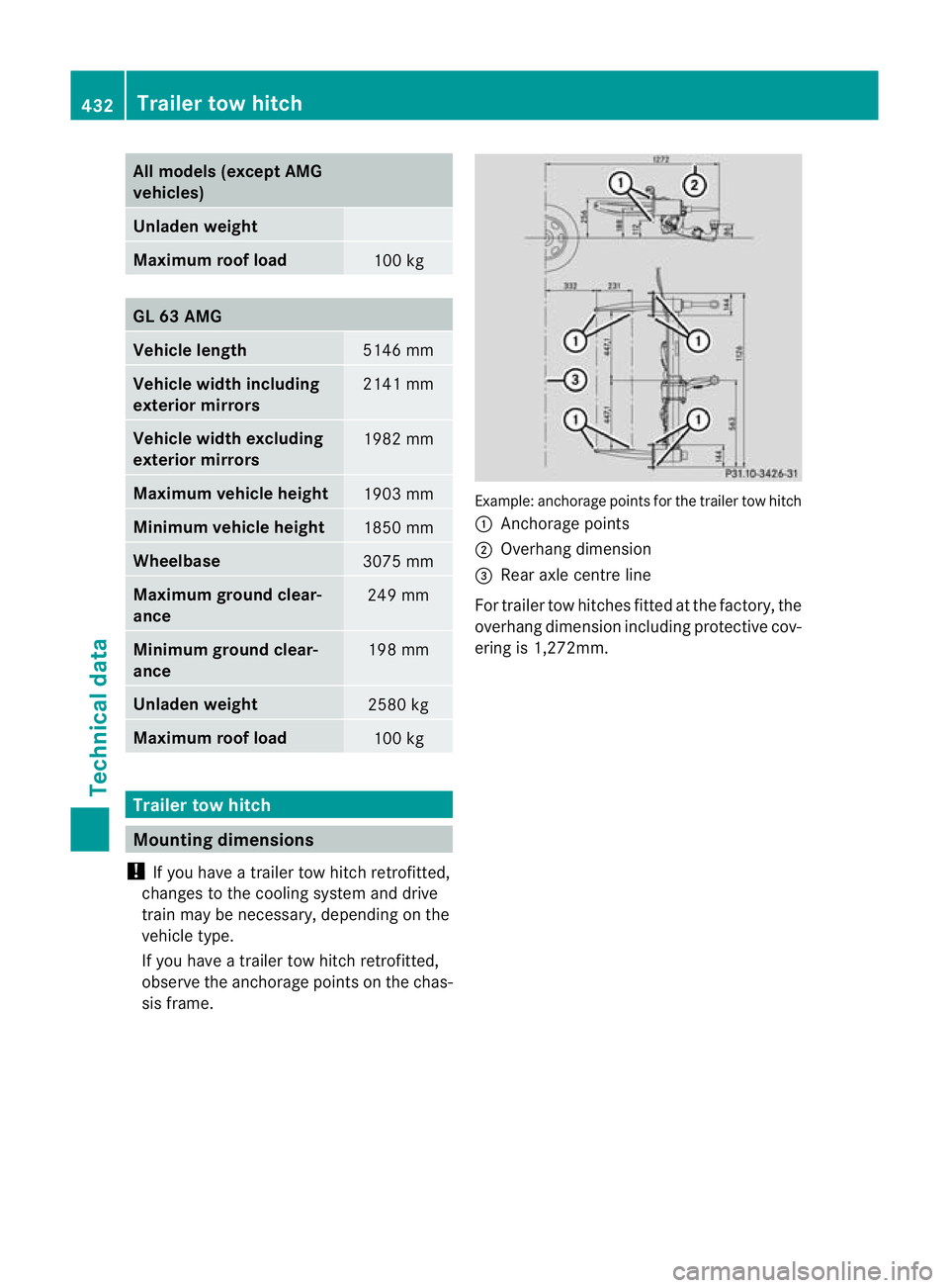
sis frame. Example: anchorage point
sfor the trailer tow hitch
: Anchorage points
; Overhang dimension
= Rear axle centre line
For traile rtow hitches fit tedatt he factory, the
overhang dimension includin gprotective cov-
ering is 1,272mm. 432
Trailer tow hitchTechnical data