width MERCEDES-BENZ GL350 BlueTEC 2011 X164 Owner's Manual
[x] Cancel search | Manufacturer: MERCEDES-BENZ, Model Year: 2011, Model line: GL350 BlueTEC, Model: MERCEDES-BENZ GL350 BlueTEC 2011 X164Pages: 376, PDF Size: 17.39 MB
Page 8 of 376
Central lockingAutomatic locking (on-board
computer) ...................................... 224
SmartKey ......................................... 72
Changing bulbs
Headlamps ..................................... 120
Changing gears .................................. 154
Changing the programming SmartKey ......................................... 75
Checklist
After driving off-road ...................... 175
Before driving off-road ...................175
Child-proof locks
Rear doors ....................................... 64
Special seat belt retractor ...............61
Children
In the vehicle ................................... 59
Restraint systems ............................ 59
Child seat
Automatic recognition .....................48
Automatic recognition/air bag
deactivation, self-test ......................50
ISOFIX (LATCH-type child seat
anchors) ........................................... 62
Special seat belt retractor ...............61
Top Tether ....................................... 62
Troubleshooting ............................... 51
Cigarette lighter ................................ 280
Climate control Activating/deactivating .................136
Activating/deactivating air-
recirculation mode .........................141
Controlling automatically ...............138
Cooling with air dehumidification ..137
Defrosting the windshield ..............140
Demisting the windows .................. 141
Dual-zone automatic climate
control ........................................... 131
Important safety information .........130
Indicator lamp ................................ 138
Multi-zone automatic climate
control ........................................... 132
Problems with "cooling with air
dehumidification" ........................... 138
Problems with the rear window
heating .......................................... 141
Rear control panel .................133, 136
Refrigerant ..................................... 369Setting the air distribution .............140
Setting the airflow .........................140
Setting the air vents ......................143
Setting the temperature ................139
Setting the temperature (rear
compartment) ................................ 139
Switching the MONO function on/
off .................................................. 140
Switching the rear window
heating on/off ............................... 141
Switching the residual heat
function on/off .............................. 142
Clock (on-board computer) ............... 222
Cockpit ................................................. 27
Combination switch .......................... 117
Compass ............................................ 291
Calling up ....................................... 291
Consumption statistics (on-board
computer) .......................................... 227
Convenience closing feature .............. 87
Convenience opening feature ............ 86
Coolant (engine) Checking the level .........................297
Display message ............................ 240
Notes ............................................. 369
Temperature gauge ........................ 218
Cooling
see Climate control
Cornering light (display message) ... 237
Crash-responsive emergency
lighting ............................................... 119
Crossbar Installing ........................................ 274
Setting the span width ...................276
Cross bar ............................................ 273
Cruise control .................................... 179
Cruise control lever .......................179
Display message ............................ 246
Cup holder ......................................... 277
Center console .............................. 277
Rear compartment .........................278
third row of seats ........................... 278
Current fuel consumption (on-
board computer) ............................... 227
Customer Assistance Center (CAC) ............................................... 22
Customer Relations Department ....... 236IndexBA 164.8 USA, CA Edition B 2011; 1; 2, en-USd2sboikeVersion: 3.0.3.52010-04-21T15:08:44+02:00 - Seite 6
Page 57 of 376
RPosition the lap belt as low as possible on
your hips and not across the abdomen. If
the lap belt is positioned across your
abdomen, it could cause serious injuries in
a crash.
R Never wear seat belts over rigid or
breakable objects in or on your clothing,
such as eyeglasses, pens, keys etc., as
these might cause injuries.
R Make sure the seat belt is always routed
snugly. Take special care of this when
wearing loose clothing.
R Never use a seat belt for more than one
person at a time. Do not fasten a seat belt
around a person and another person or
other objects at the same time.
R Seat belts should not be worn twisted. In a
crash, you would not have the full width of
the seat belt to distribute impact forces.
The twisted seat belt against your body
could cause injuries.
R Pregnant women should also always use a
lap-shoulder belt. The lap belt portion
should be positioned as low as possible on
the hips to avoid any possible pressure on
the abdomen.
R Place the seat backrest in a position that is
as upright as possible.
R Check your seat belt during travel to make
sure it is properly positioned.
R Never place your feet on the instrument
panel, dashboard, or on the seat. Always
keep both feet on the floor in front of the
seat.
R When using a seat belt to secure infant
restraints, toddler restraints, or children in
booster seats, always follow the child seat
manufacturer's instructions.GWarning
Do not pass seat belts over sharp edges. They
could tear.
Do not allow the seat belt to get caught in the
door or in the seat adjustment mechanism.
This could damage the seat belt.
Never attempt to make modifications to seat
belts. This could impair the effectiveness of
the seat belts.
Fastening seat beltsGWarning
According to accident statistics, children are
safer when properly restrained on the rear
seats than on the front-passenger seat. Thus,
we strongly recommend that children be
placed in the rear seat whenever possible.
Regardless of seating position, children 12
years old and under must be seated and
properly secured in an appropriately sized
child restraint system or booster seat
recommended for the size and weight of the
child. For additional information, see the
"Children in the vehicle" section.
A child's risk of serious or fatal injuries is
significantly increased if the child restraints
are not properly secured in the vehicle and/
or the child is not properly secured in the child
restraint.
GWarning
Canada only: children 12 years old and under
may ride on the front seat if a BabySmart™
compatible child restraint system is installed
on the front-passenger seat. Use only
Mercedes-Benz approved BabySmart™
compatible child restraint systems. A
BabySmart™ compatible child restraint
system will deactivate the front-passenger
front air bag when installed properly. The
front-passenger front air bag will not be
deactivated if the child restraint systems that
are installed are not BabySmart™ compatible
or if BabySmart™ compatible child restraint
systems are not installed correctly. If the
front-passenger front air bag is deployed in a
collision, the child could be struck by the air
bag. This could lead to serious or fatal injury.
Occupant safety55SafetyBA 164.8 USA, CA Edition B 2011; 1; 2, en-USd2sboikeVersion: 3.0.3.52010-04-21T15:08:44+02:00 - Seite 55Z
Page 190 of 376
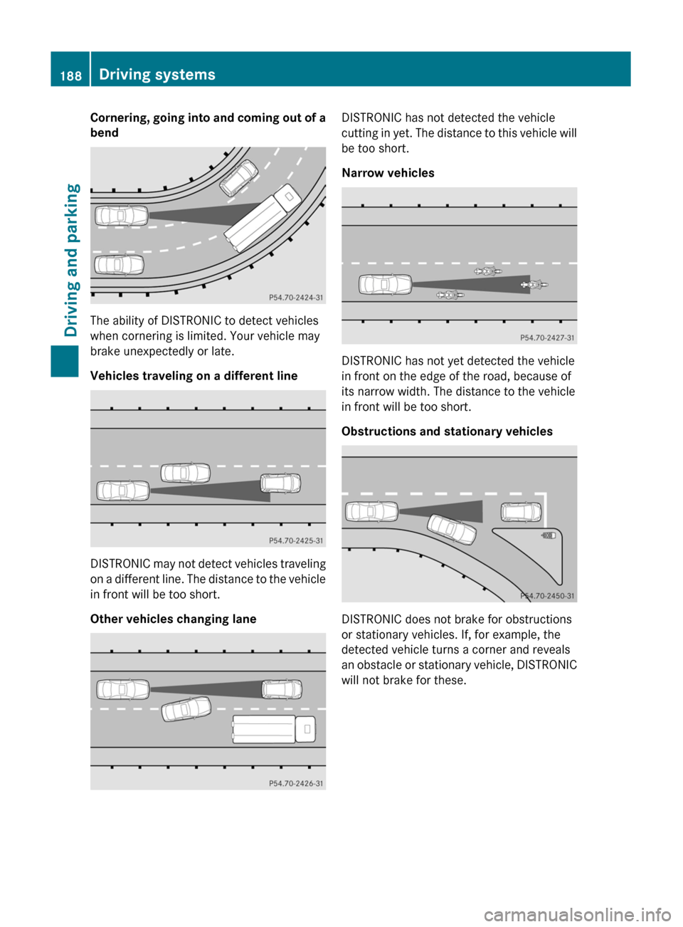
Cornering, going into and coming out of a
bend
The ability of DISTRONIC to detect vehicles
when cornering is limited. Your vehicle may
brake unexpectedly or late.
Vehicles traveling on a different line
DISTRONIC may not detect vehicles traveling
on a different line. The distance to the vehicle
in front will be too short.
Other vehicles changing lane
DISTRONIC has not detected the vehicle
cutting in yet. The distance to this vehicle will
be too short.
Narrow vehicles
DISTRONIC has not yet detected the vehicle
in front on the edge of the road, because of
its narrow width. The distance to the vehicle
in front will be too short.
Obstructions and stationary vehicles
DISTRONIC does not brake for obstructions
or stationary vehicles. If, for example, the
detected vehicle turns a corner and reveals
an obstacle or stationary vehicle, DISTRONIC
will not brake for these.
188Driving systemsDriving and parking
BA 164.8 USA, CA Edition B 2011; 1; 2, en-USd2sboikeVersion: 3.0.3.52010-04-21T15:08:44+02:00 - Seite 188
Page 202 of 376
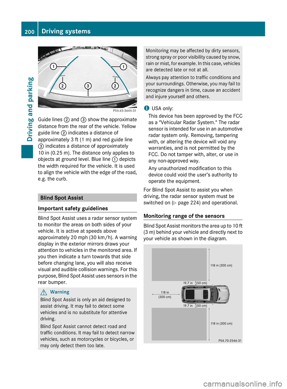
Guide lines ; and = show the approximate
distance from the rear of the vehicle. Yellow
guide line ; indicates a distance of
approximately 3 ft (1 m) and red guide line
= indicates a distance of approximately
10 in (0.25 m). The distance only applies to
objects at ground level. Blue line : depicts
the width required for the vehicle. It is used
to align the vehicle with the edge of the road,
e.g. the curb.
Blind Spot Assist
Important safety guidelines
Blind Spot Assist uses a radar sensor system
to monitor the areas on both sides of your
vehicle. It is active at speeds above
approximately 20 mph (30 km/h). A warning
display in the exterior mirrors draws your
attention to vehicles in the monitored area. If
you then indicate a turn towards that side
before changing lane, you will also receive
visual and audible collision warnings. For this
purpose, Blind Spot Assist uses sensors in the
rear bumper.
GWarning
Blind Spot Assist is only an aid designed to
assist driving. It may fail to detect some
vehicles and is no substitute for attentive
driving.
Blind Spot Assist cannot detect road and
traffic conditions. It may fail to detect narrow
vehicles, such as motorcycles or bicycles, or
may only detect them too late.
Monitoring may be affected by dirty sensors,
strong spray or poor visibility caused by snow,
rain or mist, for example. In this case, vehicles
are detected late or not at all.
Always pay attention to traffic conditions and
your surroundings. Otherwise, you may fail to
recognize dangers in time, cause an accident
and injure yourself and others.
iUSA only:
This device has been approved by the FCC
as a "Vehicular Radar System." The radar
sensor is intended for use in an automotive
radar system only. Removing, tampering
with, or altering the device will void any
warranties, and is not permitted by the
FCC. Do not tamper with, alter, or use in
any non-approved way.
Any unauthorized modification to this
device could void the user’s authority to
operate the equipment.
For Blind Spot Assist to assist you when
driving, the radar sensor system must be
switched on (Y page 224) and operational.
Monitoring range of the sensors
Blind Spot Assist monitors the area up to 10 ft
(3 m) behind your vehicle and directly next to
your vehicle as shown in the diagram.
200Driving systemsDriving and parking
BA 164.8 USA, CA Edition B 2011; 1; 2, en-USd2sboikeVersion: 3.0.3.52010-04-21T15:08:44+02:00 - Seite 200
Page 203 of 376
GWarning
Blind Spot Assist monitors certain areas in the
immediate vicinity of your vehicle. Vehicles
that approach and drive past at high speeds
are not detected. There is no display and no
warning.
If the lanes are very wide, it may not be
possible to monitor the complete width of the
neighboring lane. For this reason, vehicles in
the next lane may not be detected, especially
if they are driving in a staggered formation.
This may be the case if vehicles are driving at
that edge of their lane which is furthest away
from your vehicle.
Always pay attention to traffic conditions and
your surroundings. Otherwise, you may fail to
recognize dangers in time, cause an accident
and injure yourself and others.
If the lanes are narrow, the system may be
unable to distinguish the neighboring lane
from the one beyond it. For this reason, the
system may indicate vehicles in the farther
lane, especially if the vehicles are driving in a
staggered formation in different lanes. In
particular, this may be the case if the vehicles
are driving at that edge of their lane which is
nearest your vehicle.
Due to the nature of the system:
R warnings may be issued unnecessarily
when driving close to crash barriers or
similar solid lane borders.
R the warning may be interrupted when
traveling next to long vehicles for extended
periods.
The two sensors for Blind Spot Assist are
integrated into the sides of the rear bumper.
Make sure that the bumper is free of dirt, ice
or slush around the sensors. For example, the
radar sensors must not be covered by bicycle
racks or overhanging loads. In the event of a
severe impact or damage to the bumpers,
have the function of the radar sensors
checked at a qualified specialist workshop,
e.g. an authorized Mercedes-Benz Center.
Blind Spot Assist may otherwise not work
properly.
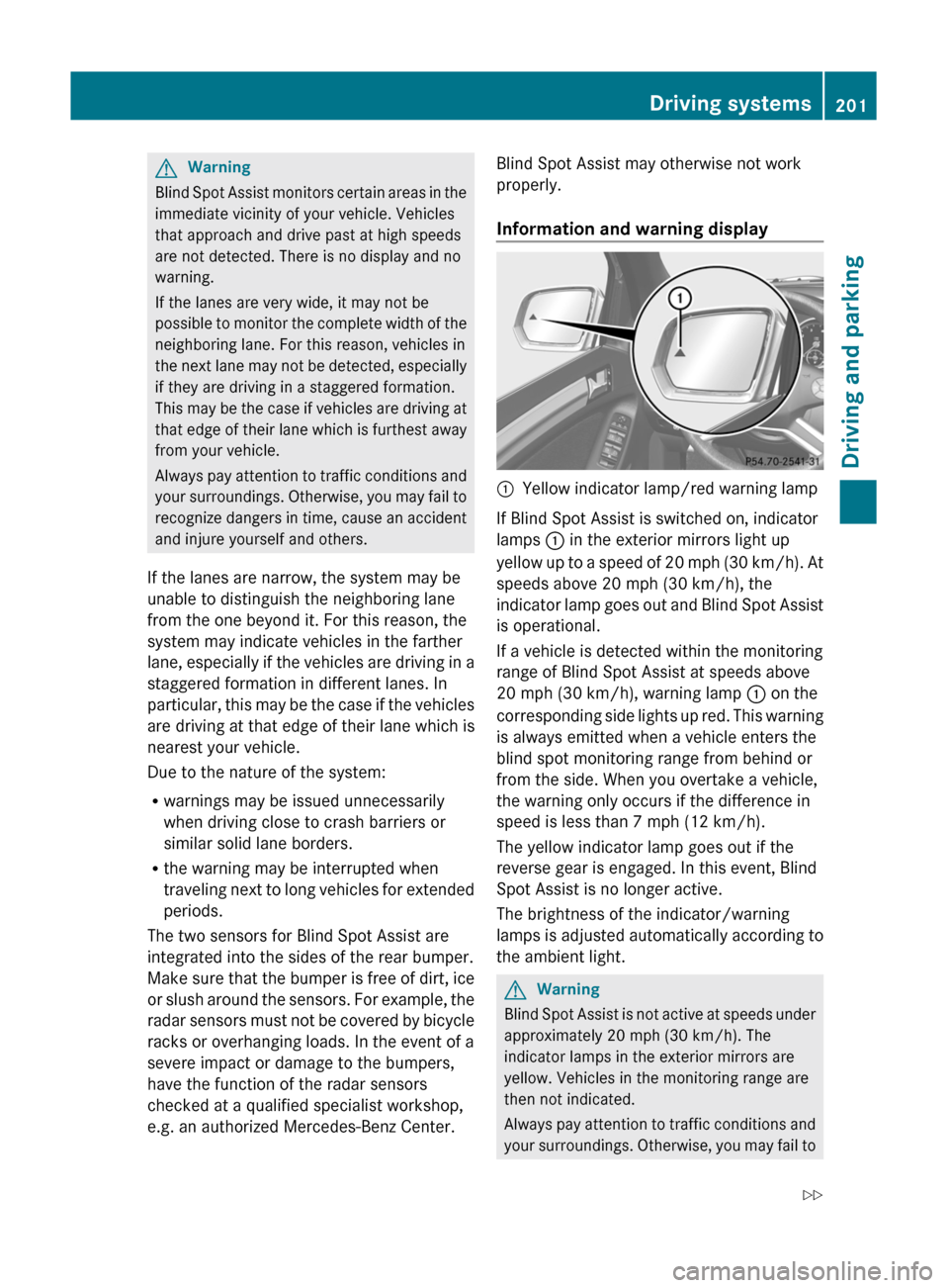
Information and warning display:Yellow indicator lamp/red warning lamp
If Blind Spot Assist is switched on, indicator
lamps : in the exterior mirrors light up
yellow up to a speed of 20 mph (30 km/h). At
speeds above 20 mph (30 km/h), the
indicator lamp goes out and Blind Spot Assist
is operational.
If a vehicle is detected within the monitoring
range of Blind Spot Assist at speeds above
20 mph (30 km/h), warning lamp : on the
corresponding side lights up red. This warning
is always emitted when a vehicle enters the
blind spot monitoring range from behind or
from the side. When you overtake a vehicle,
the warning only occurs if the difference in
speed is less than 7 mph (12 km/h).
The yellow indicator lamp goes out if the
reverse gear is engaged. In this event, Blind
Spot Assist is no longer active.
The brightness of the indicator/warning
lamps is adjusted automatically according to
the ambient light.
GWarning
Blind Spot Assist is not active at speeds under
approximately 20 mph (30 km/h). The
indicator lamps in the exterior mirrors are
yellow. Vehicles in the monitoring range are
then not indicated.
Always pay attention to traffic conditions and
your surroundings. Otherwise, you may fail to
Driving systems201Driving and parkingBA 164.8 USA, CA Edition B 2011; 1; 2, en-USd2sboikeVersion: 3.0.3.52010-04-21T15:08:44+02:00 - Seite 201Z
Page 211 of 376
Message in the multifunction display
Diff. Lock System Overheated -
Wait briefly.
The differential lock system has overheated
and briefly disengaged.XContinue driving.
The differential locks cool off and are soon
available once again.
Towing a trailer
Notes on towing a trailer
Important safety instructions
GWarning!
Failure to use proper equipment and driving
technique can result in a loss of vehicle
control when towing a trailer.
Improper towing or failure to follow the
instructions in this manual can result in
vehicle damage and/or serious personal
injury. Follow the guidelines below carefully
to assure safe trailer operation.
Contact an authorized Mercedes-Benz Center
should you require an explanation of
information contained in this manual.
General information
R Only install an approved trailer coupling on
your vehicle.
Further information on availability and on
installation is available from any authorized
Mercedes-Benz Center.
R The bumpers of your vehicle are not
suitable for installing detachable trailer
couplings.
R Do not install hired trailer couplings or
other detachable trailer couplings on the
bumpers of your vehicle.
R To reduce the risk of damage to the ball
coupling, remove it from the ball coupling
recess when not in use.
Coupling up a trailerGWarning!
While you are coupling or decoupling a trailer,
make sure nobody locks or unlocks the
vehicle and/or opens or closes doors or the
tailgate.
The vehicle’s level could change and you
could endanger yourself and/or others as a
result.
Make sure that you do not operate the ADS
button or the vehicle level control system
when coupling/decoupling the trailer.
Observe the maximum permissible trailer
dimensions (width and length).
Most federal states and all Canadian
provinces require by law:
R safety chains between the towing vehicle
and the trailer. The chains should be cross-
wound under the trailer drawbar. They must
be fastened to the vehicle's trailer
coupling, not to the bumper or the axle.
Allow for enough play in the chains to
facilitate turning tight corners.
R a separate brake system for certain types
of trailer.
R a safety switch for braked trailers. Check
the specific legal requirements applicable
to your federal state.
If the trailer detaches from the towing
vehicle, the safety switch applies the
trailer's brakes.
! Do not connect the trailer's brake system
(if featured) to the hydraulic brake system
of the towing vehicle, as the latter is
equipped with an anti-lock brake system.
Doing so will result in a loss of function of
the brake systems of both the vehicle and
the trailer.
i The vehicle's wiring harness features a
line to the brake indicator lamp.
Towing a trailer209Driving and parkingBA 164.8 USA, CA Edition B 2011; 1; 2, en-USd2sboikeVersion: 3.0.3.52010-04-21T15:08:44+02:00 - Seite 209Z
Page 277 of 376
accessories and/or the objects attached to
them could come loose from the vehicle,
thereby injuring you and other persons and/
or causing damage to property, including
damage to your vehicle.
! Have a second person assist you when
installing the crossbars. Otherwise, the
vehicle could be damaged.
! Objects that are attached to crossbar
system accessories must not limit or
obstruct the movement of the sliding
sunroof. Otherwise, the tilt/sliding sunroof
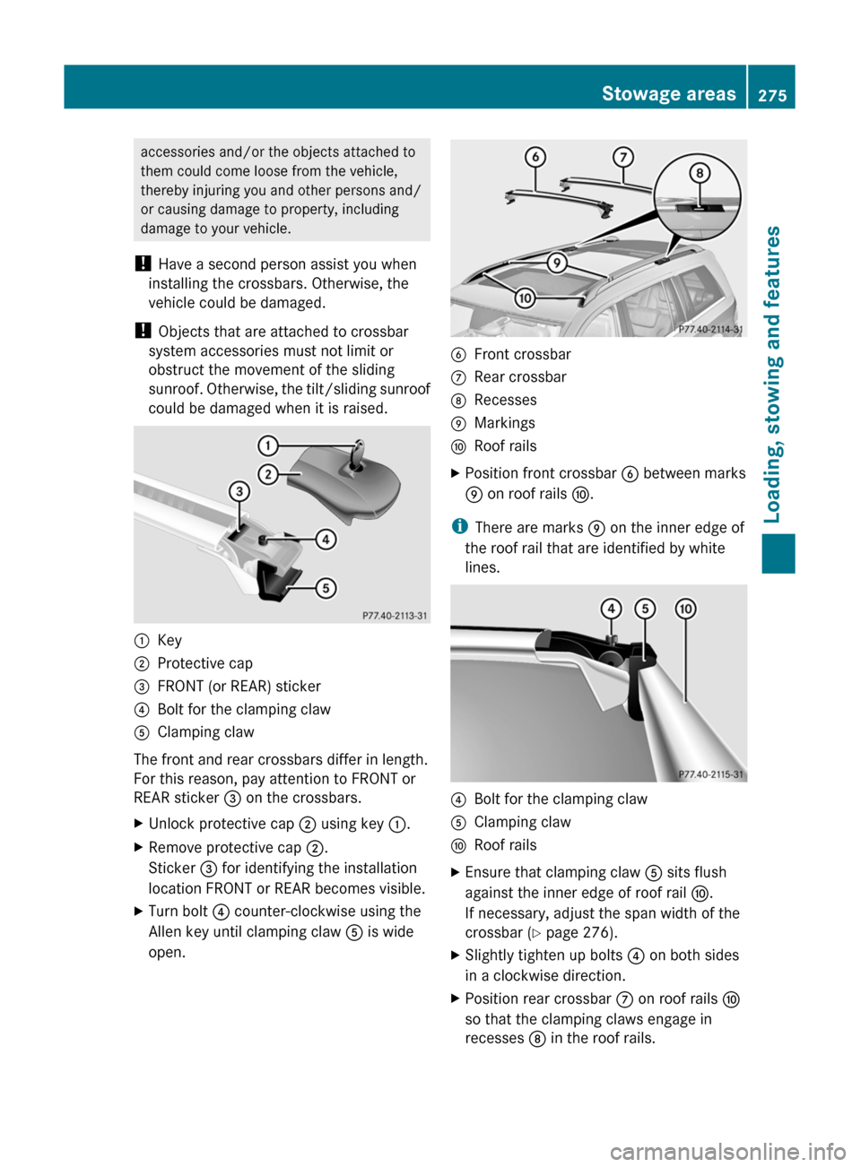
could be damaged when it is raised.:Key;Protective cap=FRONT (or REAR) sticker?Bolt for the clamping clawAClamping claw
The front and rear crossbars differ in length.
For this reason, pay attention to FRONT or
REAR sticker = on the crossbars.
XUnlock protective cap ; using key :.XRemove protective cap ;.
Sticker = for identifying the installation
location FRONT or REAR becomes visible.XTurn bolt ? counter-clockwise using the
Allen key until clamping claw A is wide
open.BFront crossbarCRear crossbarDRecessesEMarkingsFRoof railsXPosition front crossbar B between marks
E on roof rails F.
i
There are marks E on the inner edge of
the roof rail that are identified by white
lines.
?Bolt for the clamping clawAClamping clawFRoof railsXEnsure that clamping claw A sits flush
against the inner edge of roof rail F.
If necessary, adjust the span width of the
crossbar ( Y page 276).XSlightly tighten up bolts ? on both sides
in a clockwise direction.XPosition rear crossbar C on roof rails F
so that the clamping claws engage in
recesses D in the roof rails.Stowage areas275Loading, stowing and featuresBA 164.8 USA, CA Edition B 2011; 1; 2, en-USd2sboikeVersion: 3.0.3.52010-04-21T15:08:44+02:00 - Seite 275Z
Page 278 of 376
XEnsure that clamping claw A sits flush
against the inner edge of roof rail F.
If necessary, adjust the span width of the
crossbar ( Y page 276).XSlightly tighten up bolts ? on both sides
in a clockwise direction.XTighten up bolts ? on the front and rear
crossbars. Observe the tightening torque of
4 lb/ft (6 Nm) .GWarning!
Have the tightening torque checked after
mounting the crossbars. The screws could
come loose if they are not tightened to a
torque of 4 lb-ft (6 Nm).
XAttach and lock protective caps ;.XStow the key and Allen key in the stowage
compartment under the cargo
compartment floor again ( Y page 274).
Setting the span width of the crossbars
GWarning!
Only install the crossbars at the exact
locations designated on the roof rails. The
designated locations for the front crossbars
are between the markings engraved on the
inside of the roof rails. The designated
locations for the rear crossbars are between
the gaps on the roof rails.
Otherwise, the crossbars, mounted
accessories and the objects attached to them
could come loose from the vehicle causing an
accident, thereby injuring you and other
persons and/or causing damage to property,
including damage to your vehicle.
The span width of the crossbars for your
vehicle is set at the factory. The span widths
only fit in the intended positions on the
vehicle.
Only install the crossbars at the marked
positions and observe stickers = FRONT and
REAR.
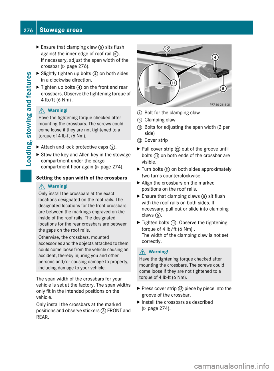
?Bolt for the clamping clawAClamping clawGBolts for adjusting the span width (2 per
side)HCover stripXPull cover strip H out of the groove until
bolts G on both ends of the crossbar are
visible.XTurn bolts G on both sides approximately
two turns counterclockwise.XAlign the crossbars on the marked
positions on the roof rails.XEnsure that clamping claws A sit flush
with the roof rails on both sides. If
necessary, pull out or slide into clamping
claws A.XTighten bolts G. Observe the tightening
torque of 4 lb/ft (6 Nm) .
The width of the clamping claw is not set
correctly.GWarning!
Have the tightening torque checked after
mounting the crossbars. The screws could
come loose if they are not tightened to a
torque of 4 lb-ft (6 Nm).
XPress cover strip H piece by piece into the
groove of the crossbar.XInstall the crossbars as described
( Y page 274).276Stowage areasLoading, stowing and features
BA 164.8 USA, CA Edition B 2011; 1; 2, en-USd2sboikeVersion: 3.0.3.52010-04-21T15:08:44+02:00 - Seite 276
Page 337 of 376
Directives to be observed
R Only mount tires and wheels of the same
type and make.
R Only mount tires of the correct size onto
the wheels.
R After mounting new tires, run them in at
moderate speeds for the first 60 miles
(100 km) as they only reach their full
performance after this distance.
R Do not use tires until they are excessively
worn as the tire traction on wet road
surfaces decreases significantly when the
tread depth is less than 1
/ 8 in (3 mm).
R If the vehicle is heavily laden, check the tire
pressure and adjust it if necessary.
R When parking your vehicle, make sure that
the tires do not get deformed by the curb
or other obstacles. If it is necessary to drive
over curbs, speed humps or similar
elevations, try to do so slowly and at an
obtuse angle. Otherwise, the tires,
particularly the sidewalls, can get
damaged.
Maintenance and care of wheels and
tires
Checking wheels and tires
GWarning
Regularly check the tires for damage.
Damaged tires can cause tire inflation
pressure loss. As a result, you could lose
control of your vehicle.
Worn, old tires can cause accidents. If the tire
tread is worn to minimum tread depth, or if
the tires have sustained damage, replace
them.
R Regularly check the wheels and tires of
your vehicle for damage (e.g. cuts,
punctures, tears, bulges on tires and
deformation or severe corrosion on
wheels), at least once a month, as well as
after driving off-road or on rough roads.
Damaged wheels can cause a loss of tire
pressure.
R Regularly check the tire tread depth and
the condition of the tread across the whole
width of the tire (Y page 335). If necessary,
turn the front wheels to full lock in order to
inspect the inner side of the tire surface.
R All wheels must have a valve cap to protect
the valve against dirt and moisture. Do not
install anything on the valve (such as tire
pressure monitoring systems) other than
the standard valve cap or other valve caps
approved by Mercedes-Benz for your
vehicle.
R Regularly check the pressure of all the tires
including the emergency spare wheel or the
spare wheel, particularly prior to long trips,
and correct the pressure as necessary
( Y page 336).
Service life of tires
The service life of tires depends on the
following factors amongst other things:
R driving style
R tire pressure
R mileage
Replace the tires after six years at the latest,
regardless of wear. This also applies to the
emergency spare wheel/spare wheel.
Tire tread
GWarning
Although the applicable federal motor vehicle
safety laws consider a tire to be worn when
the tread wear indicators (TWI) become
visible at approximately 1
/ 16 in (1.6 mm), we
recommend that you do not allow your tires
to wear down to that level. As tread depth
approaches 1
/ 8 in (3 mm), the adhesion
properties on a wet road are sharply reduced.
Maintenance and care of wheels and tires335Tires and wheelsBA 164.8 USA, CA Edition B 2011; 1; 2, en-USd2sboikeVersion: 3.0.3.52010-04-21T15:08:44+02:00 - Seite 335Z
Page 351 of 376
Quality grades can be found, where
applicable, on the tire sidewall between the
tread shoulder and maximum tire width.
For example:Tread wearTractionTemperature200AAA
All passenger car tires must conform to U.S.
federal safety requirements in addition to
these grades.
Tread wear
The tread wear grade is a comparative rating
based on the wear rate of the tire when tested
under controlled conditions on a specified
U.S. government test track. For example, a
tire graded 150 would wear one and one-half
times as well on the government test track as
a tire graded 100.
The relative performance of tires depends
upon the actual conditions of their use,
however, and may depart significantly from
the norm due to variations in driving habits,
service practices and differences in road
characteristics and climate conditions.
Traction
GWarning
The traction grade assigned to this tire is
based on straight-ahead braking traction
tests, and does not include acceleration,
cornering, hydroplaning, or peak traction
characteristics.
The traction grades, from highest to lowest,
are AA, A, B, and C. These grades represent
the tire's ability to stop on a wet surface as
measured under controlled conditions on
specified government test surfaces of asphalt
and concrete. A tire marked C may have poor
traction performance.
GWarning
If ice has formed on the road, tire traction will
be substantially reduced. Under such weather
conditions, drive, steer and brake with
extreme caution.
The safe speed on a wet, snow covered or icy
road is always lower than on dry road
surfaces.
You should pay special attention to road
conditions when temperatures are around
the freezing point.
Mercedes-Benz recommends a minimum tire
tread depth of 1/6 in (4 mm) for all four winter
tires ( Y page 171) to maintain normal driving
characteristics in winter. Winter tires can
reduce the braking distance on snow covered
surfaces in comparison to summer tires. The
braking distance is still much further than on
surfaces that are not icy or covered with
snow. Take appropriate care when driving.
! Avoid wheelspin. This can lead to damage
to the drive train which is not covered by
the Mercedes-Benz warranty conditions.
Temperature
GWarning
The temperature grade for this tire is
established for a tire that is properly inflated
and not overloaded. Excessive speed,
underinflation, or excessive loading, either
separately or in combination, can cause
excessive heat build-up and possible tire
failure.
The temperature grades are A (the highest),
B, and C, representing the tire's resistance to
the generation of heat and its ability to
dissipate heat when tested under controlled
conditions on a specified indoor laboratory
test wheel. Sustained high temperature can
cause the material of the tire to degenerate
and reduce tire life, and excessive
temperature can lead to sudden tire failure.
The grade C corresponds to a level of
Uniform Tire Quality Grading Standards349Tires and wheelsBA 164.8 USA, CA Edition B 2011; 1; 2, en-USd2sboikeVersion: 3.0.3.52010-04-21T15:08:44+02:00 - Seite 349Z