ECU MERCEDES-BENZ GLA-Class 2015 X156 Manual PDF
[x] Cancel search | Manufacturer: MERCEDES-BENZ, Model Year: 2015, Model line: GLA-Class, Model: MERCEDES-BENZ GLA-Class 2015 X156Pages: 374, PDF Size: 6.85 MB
Page 320 of 374
!
When COLLISION PREVENTION ASSIST
PLUS, DISTRONIC PLUS or the HOLD func- tion is activated, the vehicle brakes auto-
matically in certain situations. To avoid
damage to the vehicle, deactivate these
systems in the following or similar situa-
tions:
R when towing the vehicle
R in the car wash
! Only secure the tow rope or tow bar at the
towing eyes. Otherwise, the vehicle could
be damaged.
! Do not use the towing eyes for recovery
purposes as this could damage the vehicle.
If in doubt, recover the vehicle with a crane.
! When towing, pull away slowly and
smoothly. If the tractive power is too high,
the vehicles could be damaged.
! The vehicle can be towed a maximum of
30 miles (50km). The towing speed of
30 mph (50km/h) must not be exceeded.
If the vehicle has to be towed more than
30 miles (50km), the front axle must be
raised or the entire vehicle raised and
transported.
! Do not tow with sling-type equipment.
This could damage the vehicle.
! If you tow or tow-start another vehicle, its
weight must not exceed the maximum per- missible gross vehicle weight of your vehi-
cle.
If the vehicle can no longer be driven because
of an accident or breakdown, you have the
following options:
R transporting the vehicle
As a rule, you should have the vehicle trans-
ported.
R towing the vehicle with a tow rope or tow
bar
Only tow the vehicle in exceptional cases.
When towing a vehicle, the transmission must be in position N. The battery must be connected and charged.
Otherwise, you:
R cannot turn the SmartKey to position 2in
the ignition lock
R cannot release the electric parking brake
R cannot shift the transmission to position N
i The function of the electric parking brake
and the parking lock is dependent on the
on-board voltage. If the on-board voltage is low or there is a malfunction in the system,
it may not be possible to apply the released parking brake or shift the transmission to
position P.
i Switch off non-essential consumers, e.g.
the radio.
i Disarm the automatic locking feature
before the vehicle is towed (Y page 217).
You could otherwise be locked out when
pushing or towing the vehicle. Installing/removing the towing eye
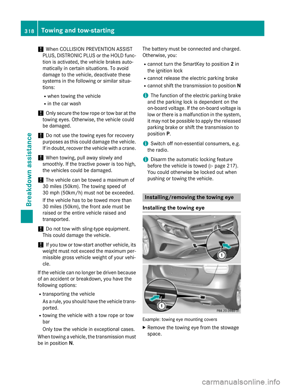
Installing the towing eye Example: towing eye mounting covers
X Remove the towing eye from the stowage
space. 318
Towing and tow-startingBreakdown assistance
Page 322 of 374
X
Shift the automatic transmission to posi-
tion P.
X Release the brake pedal.
X Release the electric parking brake.
X Switch off the automatic locking
(Y page 217).
X Switch on the hazard warning lamps
(Y page 113).
X Turn the SmartKey to position 0in the igni-
tion lock and leave the SmartKey in the
ignition lock.
Observe the important safety notes when
towing your vehicle with the front axle raised (Y page 317). Transporting the vehicle
! You may only secure the vehicle by the
wheels, not by parts of the vehicle such as
axle or steering components. Otherwise,
the vehicle could be damaged.
The towing eye can be used to pull the vehicle
onto a trailer or transporter for transporting
purposes.
X Turn the SmartKey to position 2in the igni-
tion lock.
X Shift the transmission to position N.
X Release the electric parking brake.
As soon as the vehicle has been loaded: X Prevent the vehicle from rolling away by
applying the electric parking brake.
X Shift the transmission to position P.
X Turn the SmartKey to position 0in the igni-
tion lock and remove it.
X Secure the vehicle. Notes on 4MATIC vehicles
! Vehicles with 4MATIC must not be towed
with either the front or the rear axle raised,
as doing so will damage the transmission. Vehicles with 4MATIC may only either be
towed away with both axles on the ground or
be loaded up and transported.
If the vehicle's transmission, front, or rear
axle is damaged, have the vehicle transported on a truck or trailer.
In the event of damage to the electrical
system
If the battery is defective, the automatic
transmission will be locked in position P. To
shift the automatic transmission to position
N, you must provide power to the vehicle's
electrical system in the same way as when
jump-starting (Y page 315).
Have the vehicle transported on a transporter
or trailer. Tow-starting (emergency engine
starting)
! Vehicles with automatic transmission
must not be tow-started. You could other-
wise damage the automatic transmission.
i You can find information on "Jump-start-
ing" under (Y page 315). Fuses
Important safety notes
G
WARNING
If you manipulate or bridge a faulty fuse or if
you replace it with a fuse with a higher amper- age, the electric cables could be overloaded.
This could result in a fire. There is a risk of an
accident and injury.
Always replace faulty fuses with the specified
new fuses having the correct amperage.
! Only use fuses that have been approved
for Mercedes-Benz vehicles and which
have the correct fuse rating for the system concerned. Only use fuses marked with an
"S". Otherwise, components or systems
could be damaged. 320
FusesBreakdown assistance
Page 323 of 374
The fuses in your vehicle serve to close down
faulty circuits. If a fuse blows, all the compo-
nents on the circuit and their functions stop
operating.
Blown fuses must be replaced with fuses of
the same rating, which you can recognize by
the color and value. The fuse ratings are listed in the fuse allocation chart.
If a newly inserted fuse also blows, have the
cause traced and rectified at a qualified spe-
cialist workshop, e.g. an authorized
Mercedes-Benz Center. Before changing a fuse
X Secure the vehicle against rolling away
(Y page 159).
X Switch off all electrical consumers.
X Turn the SmartKey to position 0in the igni-
tion lock and remove it (Y page 143). All
indicator lamps in the instrument cluster
must be off.
The fuses are located in various fuse boxes:
R Fuse box in the engine compartment on the
left-hand side of the vehicle, when viewed
in the direction of travel
R Fuse box in the front-passenger footwell
The fuse allocation chart is on the fuse box in
the front-passenger footwell (Y page 322).Fuse box in the engine compartment
G
WARNING
When the hood is open and the windshield
wipers are set in motion, you can be injured by the wiper linkage. There is a risk of injury.
Always switch off the windshield wipers and
the ignition before opening the hood.
! Make sure that no moisture can enter the
fuse box when the cover is open.
! When closing the cover, make sure that it
is lying correctly on the fuse box. Moisture seeping in or dirt could otherwise impair
the operation of the fuses.
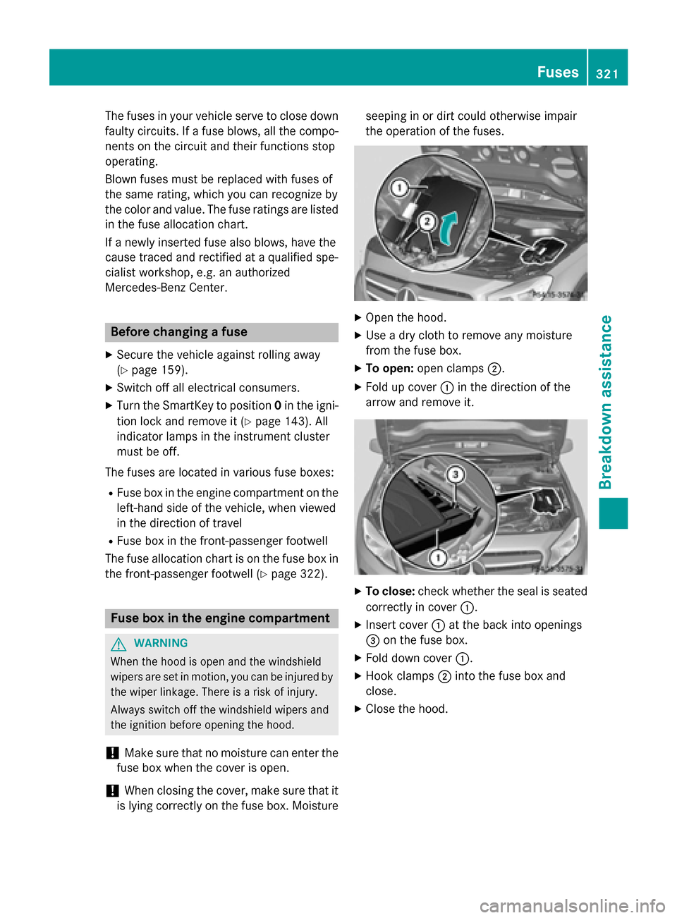
X
Open the hood.
X Use a dry cloth to remove any moisture
from the fuse box.
X To open: open clamps 0044.
X Fold up cover 0043in the direction of the
arrow and remove it. X
To close: check whether the seal is seated
correctly in cover 0043.
X Insert cover 0043at the back into openings
0087 on the fuse box.
X Fold down cover 0043.
X Hook clamps 0044into the fuse box and
close.
X Close the hood. Fuses
321Breakdown assistance Z
Page 333 of 374
Information on air pressure for the tires on
your vehicle can be found:
R on the vehicle's Tire and Loading Informa-
tion placard on the B-pillar
R on the tire pressure label on the fuel filler
flap
R in the "Tire pressure information" section
Checking tire pressures manually To determine and set the correct tire pres-
sure, proceed as follows:
X
Remove the valve cap of the tire that is to
be checked.
X Press the tire pressure gauge securely onto
the valve.
X Read the tire pressure and compare it with
the recommended value on the Tire and
Loading Information placard on the B-pillar on the driver's side of your vehicle.
X If necessary, increase the tire pressure to
the recommended value (Y page 328).
X If the tire pressure is too high, release air by
pressing down the metal pin in the valve
using the tip of a pen, for example. Then,
check the tire pressure again using the tire
pressure gauge.
X Screw the valve cap onto the valve.
X Repeat these steps for the other tires. Tire pressure loss warning system
(Canada only)
General notes While the vehicle is in motion, the tire pres-
sure loss warning system monitors the set
tire pressure using the rotational speed of the wheels. This enables the system to detect
significant pressure loss in a tire. If the speed
of rotation of a wheel changes as a result of a loss of pressure, a corresponding warning
message will appear in the multifunction dis- play. You can recognize the tire pressure loss warn-
ing in the multifunction display in the Serv.
Serv.
menu, by the Run RunFlat
Flat Indicator
Indicator Active
Active
Press 'OK' to Restart
Press 'OK' to Restart message. Further
information on the message display can be
found under "Restarting the tire pressure loss
warning system" (Y page 331).
Important safety notes The tire pressure warning system does not
warn you of an incorrectly set tire pressure.
Observe the notes on the recommended tire
pressure (Y page 328).
The tire pressure loss warning does not
replace the need to regularly check the tire
pressure. An even loss of pressure on several tires at the same time cannot be detected by
the tire pressure loss warning system.
The tire pressure monitor is not able to warn
you of a sudden loss of pressure, e.g. if the
tire is penetrated by a foreign object. In the
event of a sudden loss of pressure, bring the
vehicle to a halt by braking carefully. Avoid
abrupt steering maneuvers.
The function of the tire pressure loss warning system is limited or delayed if:
R snow chains are mounted on your vehicle's
tires.
R road conditions are wintry.
R you are driving on sand or gravel.
R you adopt a very sporty driving style (cor-
nering at high speeds or driving with high
rates of acceleration).
R you are driving with a heavy load (in the
vehicle or on the roof).
Restarting the tire pressure loss warn-
ing system Restart the tire pressure loss warning system
if you have:
R changed the tire pressure
R changed the wheels or tires
R mounted new wheels or tires Tire pressure
331Wheels and tires Z
Page 349 of 374
Tire pressure
This is pressure inside the tire applying an
outward force to each square inch of the tire's
surface. The tire pressure is specified in
pounds per square inch (psi), in kilopascal
(kPa) or in bar. The tire pressure should only
be corrected when the tires are cold. Tire pressure of cold tires
The tires are cold:
R if the vehicle has been parked without
direct sunlight on the tires for at least three
hours and
R if the vehicle has not been driven further
than 1 mile (1.6 km) Tread
The part of the tire that comes into contact
with the road. Bead
The tire bead ensures that the tire sits
securely on the wheel. There are several steel
wires in the bead to prevent the tire from
coming loose from the wheel rim. Sidewall
The part of the tire between the tread and the
bead. Weight of optional extras
The combined weight of those optional extras
that weigh more than the replaced standard
part and more than 2.3 kg (5 lbs). These
optional extras, such as high-performance
brakes, level control, a roof rack or a high-
performance battery, are not included in the
curb weight and the weight of the accesso-
ries. TIN (Tire Identification Number)
This is a unique identifier which can be used
by a tire manufacturer to identify tires, for
example for a product recall, and thus identify the purchasers. The TIN is made up of the
manufacturer's identity code, tire size, tire
type code and the manufacturing date. Load bearing index
The load bearing index (also load index) is a
code that contains the maximum load bearing
capacity of a tire. Traction
Traction is the result of friction between the
tires and the road surface. Treadwear indicators
Narrow bars (tread wear bars) that are dis-
tributed over the tire tread. If the tire tread is level with the bars, the wear limit of 00CDin
(1.6 mm) has been reached. Occupant distribution
The distribution of occupants in a vehicle at
their designated seating positions. Total load limit
Nominal load and luggage load plus
68 kilograms (150 lb) multiplied by the num-
ber of seats in the vehicle. Changing a wheel
Flat tire
You can find information on what to do in the
event of a flat tire in the "Flat tire" section
(Y page 306). Information on driving with
MOExtended tires in the event of a flat tire can Changing a
wheel
347Wheels an d tires Z
Page 351 of 374
X
Remove the SmartKey from the ignition
lock.
X If included in the vehicle equipment,
remove the tire-change tool kit from the
vehicle.
X Secure the vehicle to prevent it from rolling
away.
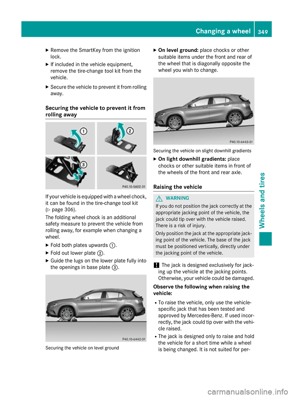
Securing the vehicle to prevent it from
rolling away If your vehicle is equipped with a wheel chock,
it can be found in the tire-change tool kit
(Y page 306).
The folding wheel chock is an additional
safety measure to prevent the vehicle from
rolling away, for example when changing a
wheel.
X Fold both plates upwards 0043.
X Fold out lower plate 0044.
X Guide the lugs on the lower plate fully into
the openings in base plate 0087.Securing the vehicle on level ground X
On level ground: place chocks or other
suitable items under the front and rear of
the wheel that is diagonally opposite the
wheel you wish to change. Securing the vehicle on slight downhill gradients
X On light downhill gradients: place
chocks or other suitable items in front of
the wheels of the front and rear axle.
Raising the vehicle G
WARNING
If you do not position the jack correctly at the appropriate jacking point of the vehicle, the
jack could tip over with the vehicle raised.
There is a risk of injury.
Only position the jack at the appropriate jack-
ing point of the vehicle. The base of the jack
must be positioned vertically, directly under
the jacking point of the vehicle.
! The jack is designed exclusively for jack-
ing up the vehicle at the jacking points.
Otherwise, your vehicle could be damaged.
Observe the following when raising the
vehicle:
R To raise the vehicle, only use the vehicle-
specific jack that has been tested and
approved by Mercedes-Benz. If used incor-
rectly, the jack could tip over with the vehi- cle raised.
R The jack is designed only to raise and hold
the vehicle for a short time while a wheel
is being changed. It is not suited for per- Changing a wheel
349Wheels andtires Z
Page 352 of 374
forming maintenance work under the vehi-
cle.
R Avoid changing the wheel on uphill and
downhill slopes.
R Before raising the vehicle, secure it from
rolling away by applying the parking brake
and inserting wheel chocks. Never disen-
gage the parking brake while the vehicle is
raised.
R The jack must be placed on a firm, flat and
non-slip surface. On a loose surface, a
large, flat, load-bearing underlay must be
used. On a slippery surface, a non-slip
underlay must be used, e.g. rubber mats.
R Do not use wooden blocks or similar
objects as a jack underlay. Otherwise, the
jack will not be able to achieve its load-
bearing capacity due to the restricted
height.
R Make sure that the distance between the
underside of the tires and the ground does not exceed 1.2 in (3 cm).
R Never place your hands and feet under the
raised vehicle.
R Do not lie under the vehicle.
R Do not start the engine when the vehicle is
raised.
R Never open or close a door or the tailgate
when the vehicle is raised.
R Make sure that no persons are present in
the vehicle when the vehicle is raised. X
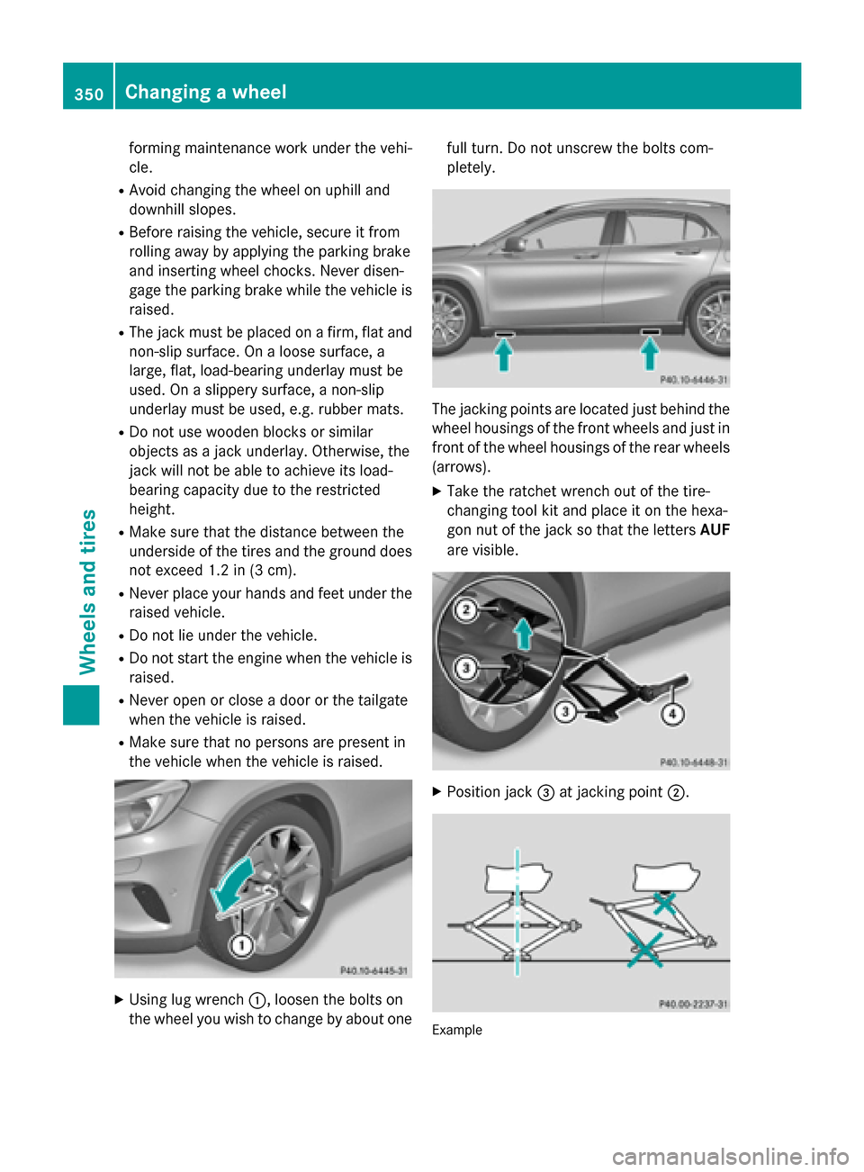
Using lug wrench 0043, loosen the bolts on
the wheel you wish to change by about one full turn. Do not unscrew the bolts com-
pletely.
The jacking points are located just behind the
wheel housings of the front wheels and just in front of the wheel housings of the rear wheels(arrows).
X Take the ratchet wrench out of the tire-
changing tool kit and place it on the hexa-
gon nut of the jack so that the letters AUF
are visible. X
Position jack 0087at jacking point 0044. Example350
Changing a wheelWheels and tires
Page 353 of 374
X
Make sure the foot of the jack is directly
beneath the jacking point.
X Turn ratchet wrench 0085until jack 0087sits
completely on jacking point 0044and the
base of the jack lies evenly on the ground.
X Turn ratchet wrench 0085until the tire is
raised a maximum of 1.2 in (3 cm) from the ground.
Removing a wheel !
Do not place wheel bolts in sand or on a
dirty surface. The bolt and wheel hub
threads could otherwise be damaged when you screw them in.
X Unscrew the wheel bolts.
X Remove the wheel.
Mounting a new wheel G
WARNING
Oiled or greased wheel bolts or damaged
wheel bolts/hub threads can cause the wheel bolts to come loose. As a result, you could
lose a wheel while driving. There is a risk of
accident.
Never oil or grease wheel bolts. In the event of damage to the threads, contact a qualified
specialist workshop immediately. Have the
damaged wheel bolts or hub threads
replaced/renewed. Do not continue driving. G
WARNING
If you tighten the wheel bolts or wheel nuts
when the vehicle is raised, the jack could tip
over. There is a risk of injury.
Only tighten the wheel bolts or wheel nuts
when the vehicle is on the ground.
Always pay attention to the instructions and
safety notes in the "Changing a wheel" sec-
tion (Y page 348).
Only use wheel bolts that have been designed for the wheel and the vehicle. For safety rea-
sons, Mercedes-Benz recommends that you
only use wheel bolts which have been approved for Mercedes-Benz vehicles and the
respective wheel.
! To prevent damage to the paintwork, hold
the wheel securely against the wheel hub
while screwing in the first wheel bolt. X
Clean the wheel and wheel hub contact
surfaces.
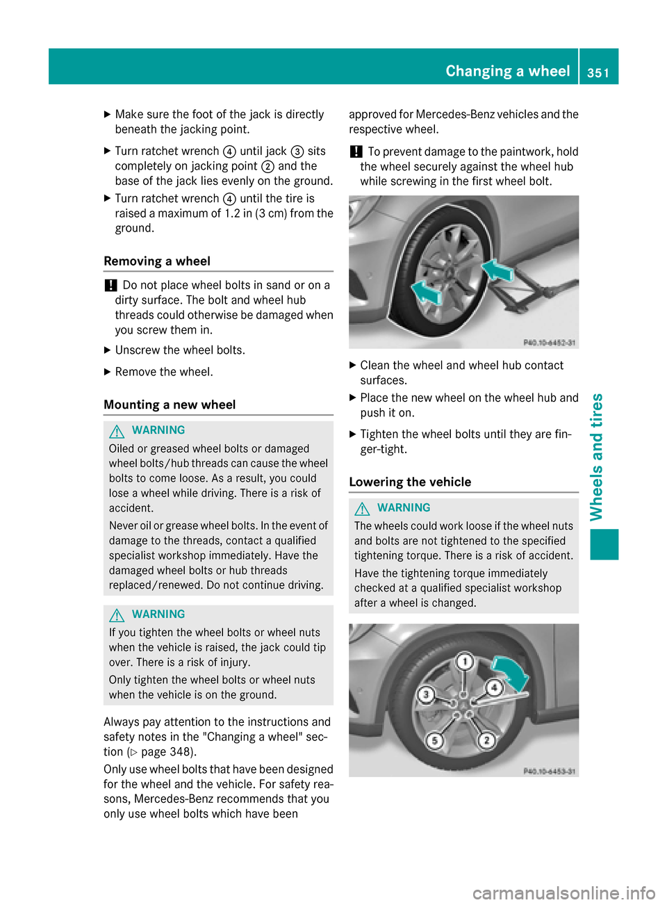
X Place the new wheel on the wheel hub and
push it on.
X Tighten the wheel bolts until they are fin-
ger-tight.
Lowering the vehicle G
WARNING
The wheels could work loose if the wheel nuts and bolts are not tightened to the specified
tightening torque. There is a risk of accident.
Have the tightening torque immediately
checked at a qualified specialist workshop
after a wheel is changed. Changing a wheel
351Wheels and tires Z