ECU MERCEDES-BENZ GLC COUPE 2016 Service Manual
[x] Cancel search | Manufacturer: MERCEDES-BENZ, Model Year: 2016, Model line: GLC COUPE, Model: MERCEDES-BENZ GLC COUPE 2016Pages: 389, PDF Size: 7.34 MB
Page 225 of 389
Coupling up a trailer
X Apply the electric parking brake manually.
X Shift the transmission to position P.
X Position the trailer on a level surface behind
the vehicle.
X Couple up the trailer.
X Establish the electrical connection between
the vehicle and the trailer.
X Check that the trailer lighting system is work-
ing.
X Push the combination switch upwards and
downwards and check whether the corre-
sponding turn signal indicator on the trailer is
flashing.
A connected trailer is only detected when the
electrical connection is established correctly
and the lighting system is working properly. The
function of other systems also depends on this, for example:
R ESP ®
R PARKTRONIC
R Active Parking Assist
R Active Blind Spot Assist
R Active Lane Keeping Assist Uncoupling a trailer
G
WARNING
If you uncouple a trailer with an engaged over- run brake, you could trap your hand between
the vehicle and the trailer drawbar. This poses a risk of injury.
Do not uncouple a trailer with an engaged
overrun brake. G
WARNING
Vehicles with level control:
If you disconnect the trailer cable, the vehicle is lowered. This can cause you or others to
become trapped between the vehicle body
and tyres, or underneath the vehicle. This
poses a risk of injury.
Make sure that no-one is in the immediate
vicinity of the wheel arch or underneath the
vehicle when disconnecting the trailer cable. !
Do not disconnect a trailer with an engaged
overrun brake. Otherwise, your vehicle could
be damaged by the rebounding of the overrun
brake.
! Remove the adapter cable before folding in
the ball coupling. You could otherwise dam-
age the rear bumper and the adapter cable.
X Apply the electric parking brake manually.
X Shift the transmission to position P.
X Switch off the engine.
X Secure the vehicle and trailer against rolling
away.
X Remove the trailer cable and uncouple the
trailer. Trailer power supply
! Accessories with a maximum power con-
sumption of 180 W can be connected to the
permanent power supply.
The trailer battery may not be charged from
the power supply.
When it leaves the factory, your vehicle's trailer
socket is equipped with a permanent power
supply and a power supply that is switched on
via the ignition lock.
The permanent power supply is supplied via
trailer socket pin 9.
The power supply that is switched on via the
ignition lock is supplied via trailer socket pin 10.
The trailer's permanent power supply is
switched off in the event of low on-board voltage
and after six hours at the latest.
You can find more information about installing
the trailer electrics at a qualified specialist work- shop.
To activate the switched power supply:
X Turn the key to position 2in the ignition lock
(Y page 144).
or
X Press the Start/Stop button twice on vehicles
with KEYLESS-GO or the KEYLESS-GO start
function (Y page 144).222
Towing a trailerDriving and parking
Page 226 of 389
To deactivate the switched power supply:
X Turn the key to position 0in the ignition lock
(Y page 144).
or
X Press the Start/Stop button once on vehicles
with KEYLESS-GO or the KEYLESS-GO start
function (Y page 144). Failure check for LEDs
If LED lamps are fitted in the trailer, a malfunc-
tion message may appear in the multifunction
display even if there is no fault. The reason for
the error message may be that the current has
fallen below the minimum of 50 mA.
To ensure reliable operation of the failure indi-
cator, each LED chain in the trailer lighting must
be guaranteed a minimum current of 50 mA. Trailer with 7-pin connector
General notes Trailer with 7-pin connector:
you can connect
to the 13-pin socket on the ball coupling using
an adapter or, if necessary, an adapter cable.
Both can be obtained at a qualified specialist
workshop. Fitting the adapter !
Make sure that there is sufficient cable play
so that the cable cannot become detached
when cornering.
! Remove the adapter cable before folding in
the ball coupling. You could otherwise dam-
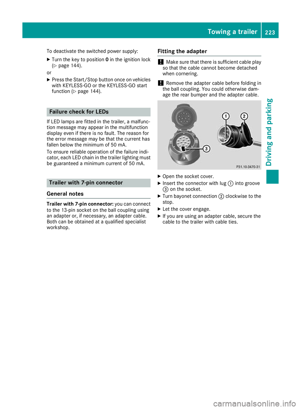
age the rear bumper and the adapter cable. X
Open the socket cover.
X Insert the connector with lug :into groove
= on the socket.
X Turn bayonet connection ;clockwise to the
stop.
X Let the cover engage.
X If you are using an adapter cable, secure the
cable to the trailer with cable ties. Towing a trailer
223Driving and parking Z
Page 227 of 389
Problems with trailer towing
Problem
Possible causes/consequences and
M
MSolutions The ball coupling has
been swivelled in but
does not reach the
securely locked position. R
The indicator lamp in the switch flashes.
R The Trailer coupling Check lock Trailer coupling Check lock message appears on the
multifunction display.
X Initiate a new swivelling procedure.
If the ball coupling does not reach the securely locked position as a
result: X Start the engine.
or
X Pull and hold the switch during the whole swivelling procedure.
If the unlocked ball coupling does not reach the securely locked posi- tion even after several attempts:
X Make sure that there is sufficient ground clearance before continu-
ing the journey.
X Consult a qualified specialist workshop.
As long as the message Trailer Trailercoupling
coupling Check
Checklock
lockis shown on
the multifunction display, no trailer should be attached. Unlocking using the
switch on the tailgate:
The ball coupling does
not swivel out even
though:
R the vehicle is station-
ary
R no trailer cable is con-
nected
R the switch was briefly
pulled The on-board voltage is too low.
X Start the engine.
If the ball coupling still does not unlock:
X Consult a qualified specialist workshop. 224
Towing a trailerDriving and parking
Page 228 of 389

Problem
Possible causes/consequences and
M
MSolutions Unlocking using the
switch on the driver's
door:
The ball coupling does
not swivel out even
though:
R the vehicle is station-
ary
R no trailer cable is con-
nected The on-board voltage is too low.
X Engage parking position P.
X Switch on the power supply.
or X Start the engine.
If the ball coupling still does not unlock: X Consult a qualified specialist workshop. The ball coupling does
not swivel out or in. The
indicator lamp in the
switch is flashing perma-
nently. The Trailer Trailer
coupling Check lock
coupling Check lock
message appears on the
multifunction display. There is a malfunction in the release electronics.
X When the ball coupling is swivelled in: pull and hold the switch
on the tailgate until the ball coupling vertically engages in a securely locked position and then engages again under the bumper.
X When the ball coupling is swivelled out: pull and hold the switch
on the tailgate until the ball coupling engages under the bumper.
If the ball coupling still does not unlock: X Consult a qualified specialist workshop. Bicycle rack
General notes
Trailer tow hitch (example with additional
guide pin)
Depending on the bicycle rack's design, you can transport up to four bicycles on it:
R When attached by clamping onto the ball cou-
pling :, the maximum payload is 75 kg. You
can transport up to three bicycles.
R When attached to the ball coupling :and
also the guide pin ;, the maximum payload is
100 kg. You can transport up to four bicycles.
The payload is calculated from the weight of the
bicycle rack and the load of the bicycle rack. To transport bicycles with a total weight
between 75 kg and 100 kg, use only bicycle
racks with additional support on the guide
pin
;. Important safety notes
G
WARNING
The bicycle rack can detach from the vehicle if
you
R exceed the permissible payload of the
trailer tow hitch
R use the bicycle rack incorrectly
R attach the bicycle rack to the ball coupling
beneath the ball head
There is a risk of an accident.
For your safety and that of other road users,
observe the following:
R Always observe the permissible payload of
the trailer tow hitch.
R Use the bicycle rack only to transport bicy-
cles. Bicycle rack
225Driving and parking
Z
Page 229 of 389
R
Always attach the bicycle rack correctly by
clamping onto the ball head and, if possible,
to the guide pin on the ball coupling as well.
R To transport four bicycles, always use bicy-
cle racks with additional support on the ball
coupling's guide pin.
R Use only bicycle racks approved by
Mercedes-Benz.
R Always comply with the bicycle rack's oper-
ating manual.
! Using unsuitable bicycle racks or using
them incorrectly can cause damage to and
fractures in the trailer tow hitch.
Use only bicycle racks approved by
Mercedes-Benz. Bicycle racks cause your vehicle's driving char-
acteristics to change. The vehicle
R is heavier
R is restricted in its acceleration and gradient-
climbing capability
R has an increased braking distance
This can impair the vehicle's handling charac-
teristics. Adapt your driving style accordingly.
Maintain a safe distance and drive carefully.
When using bicycle racks, set the tyre pressure on the rear axle of the vehicle for the maximum
load. Further information on tyre pressure can
be found on the tyre pressure table
(Y page 359). Loading instructions
The greater the distance between the load's centre of gravity and the ball head, the higher the load exerted on the trailer tow hitch.
Therefore, observe the following notes:
R Attach heavy bicycles as close as possible to the vehicle.
R Always distribute the load on the bicycle rack as symmetrically as possible to the vehicle longi-
tudinal axis.
Before loading the bicycle rack, Mercedes-Benz advises you to remove all add-on parts from the
bicycles, e.g. bicycle baskets, child seats or batteries. This will allow you to improve the aerody-
namic resistance and the bicycle rack's centre of gravity.
Always secure bicycles against slipping and check that they are firmly seated at regular intervals.
Do not use tarpaulins or other covers. This could impair the driving characteristics and rear visibility. The aerodynamic resistance would also rise, and so would the load exerted on the trailer tow hitchas a result. 226
Bicycle rackDriving an
d parking
Page 236 of 389
Displaying the range and current fuel
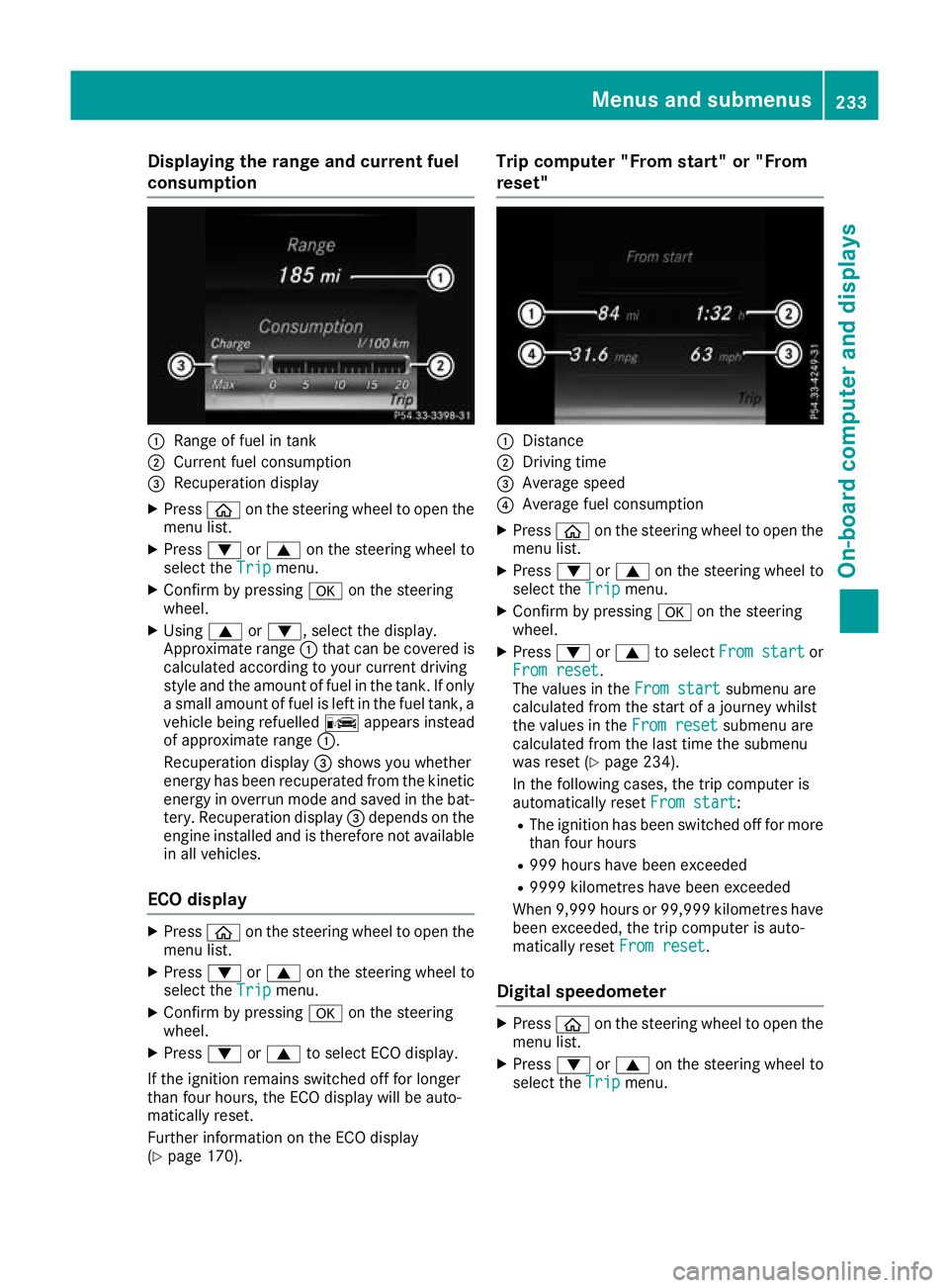
consumption :
Range of fuel in tank
; Current fuel consumption
= Recuperation display
X Press òon the steering wheel to open the
menu list.
X Press :or9 on the steering wheel to
select the Trip
Tripmenu.
X Confirm by pressing aon the steering
wheel.
X Using 9or:, select the display.
Approximate range :that can be covered is
calculated according to your current driving
style and the amount of fuel in the tank. If only a small amount of fuel is left in the fuel tank, a
vehicle being refuelled Cappears instead
of approximate range :.
Recuperation display =shows you whether
energy has been recuperated from the kinetic energy in overrun mode and saved in the bat-
tery. Recuperation display =depends on the
engine installed and is therefore not available in all vehicles.
ECO display X
Press òon the steering wheel to open the
menu list.
X Press :or9 on the steering wheel to
select the Trip
Trip menu.
X Confirm by pressing aon the steering
wheel.
X Press :or9 to select ECO display.
If the ignition remains switched off for longer
than four hours, the ECO display will be auto-
matically reset.
Further information on the ECO display
(Y page 170). Trip computer "From start" or "From
reset"
:
Distance
; Driving time
= Average speed
? Average fuel consumption
X Press òon the steering wheel to open the
menu list.
X Press :or9 on the steering wheel to
select the Trip
Trip menu.
X Confirm by pressing aon the steering
wheel.
X Press :or9 to select From start From start or
From reset
From reset.
The values in the From start From startsubmenu are
calculated from the start of a journey whilst
the values in the From reset From resetsubmenu are
calculated from the last time the submenu
was reset (Y page 234).
In the following cases, the trip computer is
automatically reset From start From start:
R The ignition has been switched off for more
than four hours
R 999 hours have been exceeded
R 9999 kilometres have been exceeded
When 9,999 hour sor 99,999 kilometres have
been exceeded, the trip computer is auto-
matically reset From reset
From reset.
Digital speedometer X
Press òon the steering wheel to open the
menu list.
X Press :or9 on the steering wheel to
select the Trip
Tripmenu. Menus and submenus
233On-board computer and displays Z
Page 256 of 389
Display messages
Possible causes/consequences and
M
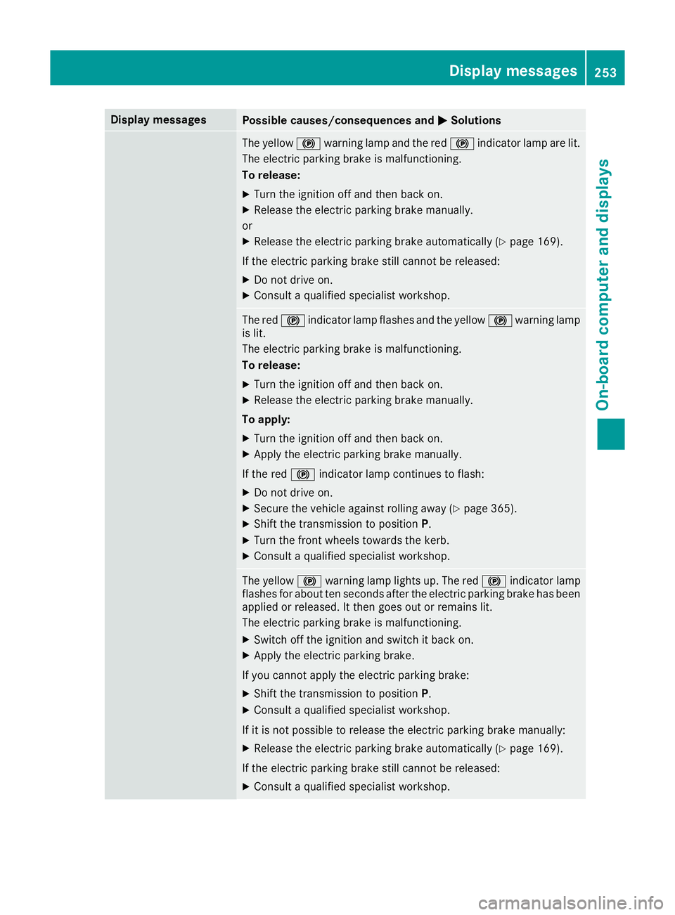
MSolutions The yellow
!warning lamp and the red !indicator lamp are lit.
The electric parking brake is malfunctioning.
To release:
X Turn the ignition off and then back on.
X Release the electric parking brake manually.
or
X Release the electric parking brake automatically (Y page 169).
If the electric parking brake still cannot be released:
X Do not drive on.
X Consult a qualified specialist workshop. The red
!indicator lamp flashes and the yellow !warning lamp
is lit.
The electric parking brake is malfunctioning.
To release:
X Turn the ignition off and then back on.
X Release the electric parking brake manually.
To apply: X Turn the ignition off and then back on.
X Apply the electric parking brake manually.
If the red !indicator lamp continues to flash:
X Do not drive on.
X Secure the vehicle against rolling away (Y page 365).
X Shift the transmission to position P.
X Turn the front wheels towards the kerb.
X Consult a qualified specialist workshop. The yellow
!warning lamp lights up. The red !indicator lamp
flashes for about ten seconds after the electric parking brake has been applied or released. It then goes out or remains lit.
The electric parking brake is malfunctioning.
X Switch off the ignition and switch it back on.
X Apply the electric parking brake.
If you cannot apply the electric parking brake:
X Shift the transmission to position P.
X Consult a qualified specialist workshop.
If it is not possible to release the electric parking brake manually: X Release the electric parking brake automatically (Y page 169).
If the electric parking brake still cannot be released:
X Consult a qualified specialist workshop. Display
messages
253On-board computer and displays Z
Page 257 of 389
Display messages
Possible causes/consequences and
M
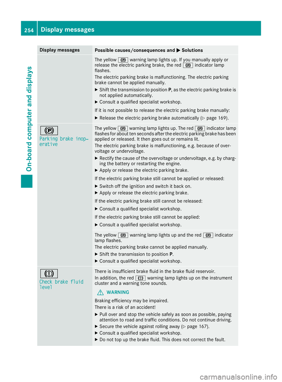
MSolutions The yellow
!warning lamp lights up. If you manually apply or
release the electric parking brake, the red !indicator lamp
flashes.
The electric parking brake is malfunctioning. The electric parking
brake cannot be applied manually.
X Shift the transmission to position P, as the electric parking brake is
not applied automatically.
X Consult a qualified specialist workshop.
If it is not possible to release the electric parking brake manually:
X Release the electric parking brake automatically (Y page 169).!
Parking brake inop‐ Parking brake inop‐
erative erative The yellow
!warning lamp lights up. The red !indicator lamp
flashes for about ten seconds after the electric parking brake has been applied or released. It then goes out or remains lit.
The electric parking brake is malfunctioning, e.g. because of over-
voltage or undervoltage.
X Rectify the cause of the overvoltage or undervoltage, e.g. by charg-
ing the battery or restarting the engine.
X Apply or release the electric parking brake.
If the electric parking brake still cannot be applied or released: X Switch off the ignition and switch it back on.
X Apply or release the electric parking brake.
If the electric parking brake still cannot be released: X Consult a qualified specialist workshop.
If the electric parking brake still cannot be applied:
X Consult a qualified specialist workshop. The yellow
!warning lamp lights up and the red !indicator
lamp flashes.
The electric parking brake cannot be applied manually.
X Shift the transmission to position P.
X Consult a qualified specialist workshop. J
Check brake fluid Check brake fluid
level level There is insufficient brake fluid in the brake fluid reservoir.
In addition, the red Jwarning lamp lights up on the instrument
cluster and a warning tone sounds.
G WARNING
Braking efficiency may be impaired.
There is a risk of an accident!
X Pull over and stop the vehicle safely as soon as possible, paying
attention to road and traffic conditions. Do not continue driving.
X Secure the vehicle against rolling away (Y page 167).
X Consult a qualified specialist workshop.
X Do not top up the brake fluid. This does not correct the fault. 254
Display
messagesOn-board computer and displays
Page 258 of 389
Display messages
Possible causes/consequences and
M
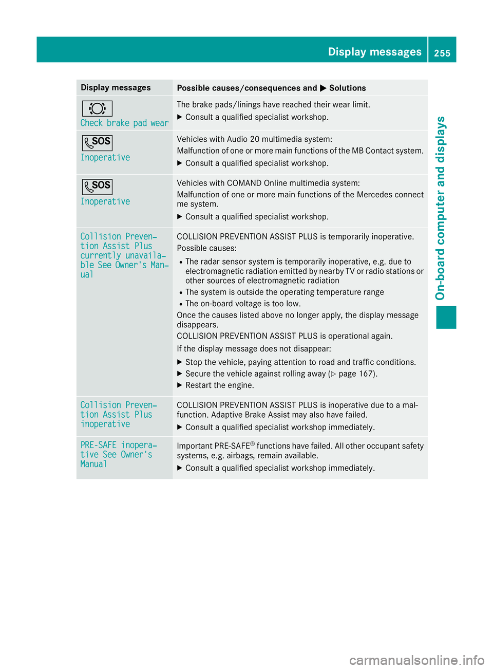
MSolutions #
Check Check
brake
brakepad
padwear
wear The brake pads/linings have reached their wear limit.
X Consult a qualified specialist workshop. G
Inoperative Inoperative Vehicles with Audio 20 multimedia system:
Malfunction of one or more main functions of the MB Contact system.
X Consult a qualified specialist workshop. G
Inoperative Inoperative Vehicles with COMAND Online multimedia system:
Malfunction of one or more main functions of the Mercedes connect
me system.
X Consult a qualified specialist workshop. Collision Preven‐ Collision Preven‐
tion Assist Plus tion Assist Plus
currently unavaila‐ currently unavaila‐
ble ble
See
SeeOwner's
Owner's Man‐
Man‐
ual
ual COLLISION PREVENTION ASSIST PLUS is temporarily inoperative.
Possible causes:
R The radar sensor system is temporarily inoperative, e.g. due to
electromagnetic radiation emitted by nearby TV or radio stations or other sources of electromagnetic radiation
R The system is outside the operating temperature range
R The on-board voltage is too low.
Once the causes listed above no longer apply, the display message
disappears.
COLLISION PREVENTION ASSIST PLUS is operational again.
If the display message does not disappear:
X Stop the vehicle, paying attention to road and traffic conditions.
X Secure the vehicle against rolling away (Y page 167).
X Restart the engine. Collision Preven‐ Collision Preven‐
tion Assist Plus tion Assist Plus
inoperative inoperative COLLISION PREVENTION ASSIST PLUS is inoperative due to a mal-
function. Adaptive Brake Assist may also have failed.
X Consult a qualified specialist workshop immediately. PRE-SAFE inopera‐ PRE-SAFE inopera‐
tive See Owner's tive See Owner's
Manual Manual
Important PRE-SAFE
®
functions have failed. All other occupant safety
systems, e.g. airbags, remain available.
X Consult a qualified specialist workshop immediately. Display
messages
255On-board computer and displays Z
Page 259 of 389
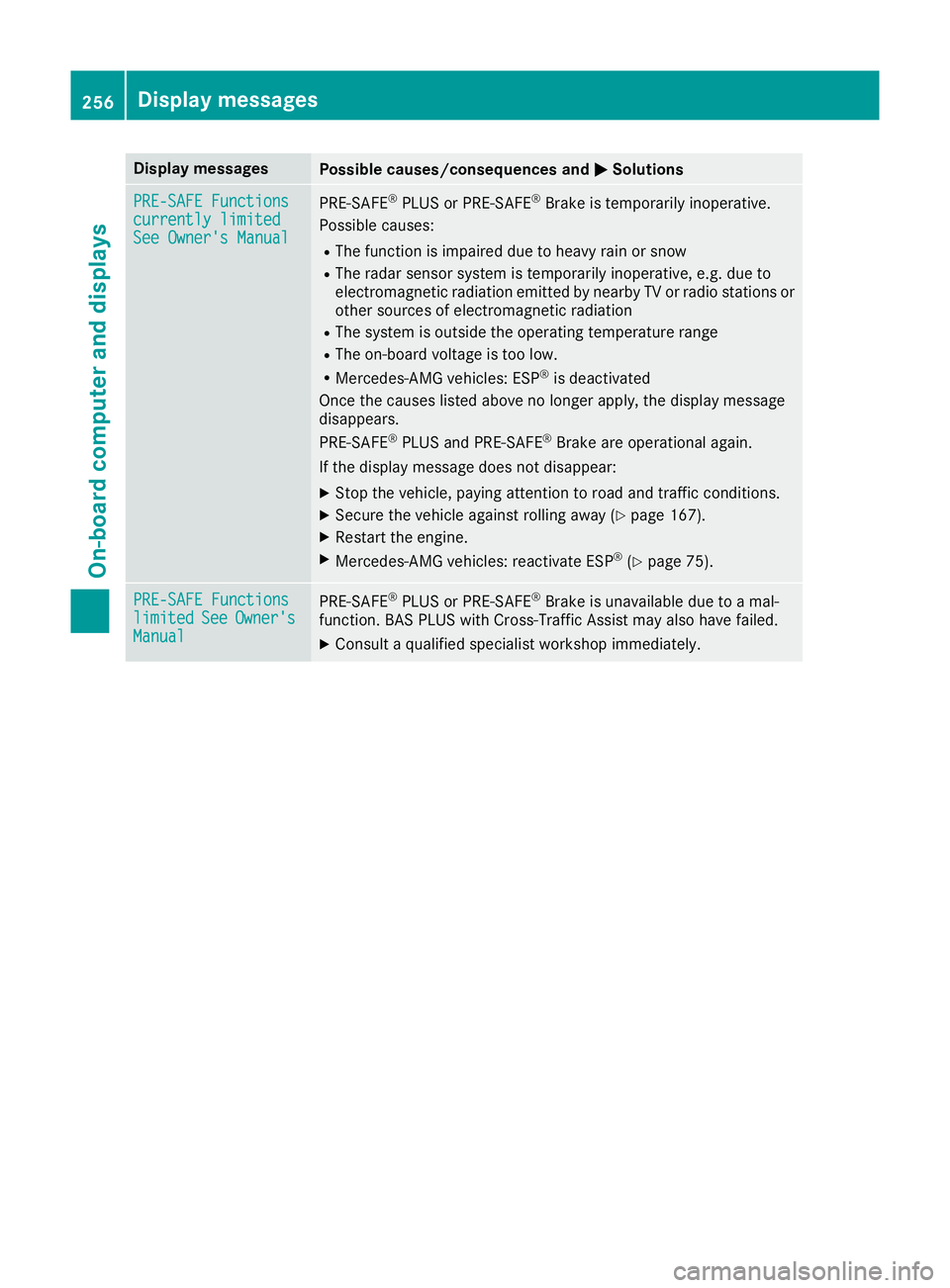
Display messages
Possible causes/consequences and
M
MSolutions PRE-SAFE Functions
PRE-SAFE Functions
currently limited currently limited
See Owner's Manual See Owner's Manual
PRE
‑SAFE ®
PLUS or PRE‑ SAFE®
Brake is temporarily inoperative.
Possible causes:
R The function is impaired due to heavy rain or snow
R The radar sensor system is temporarily inoperative, e.g. due to
electromagnetic radiation emitted by nearby TV or radio stations or
other sources of electromagnetic radiation
R The system is outside the operating temperature range
R The on-board voltage is too low.
R Mercedes-AMG vehicles: ESP ®
is deactivated
Once the causes listed above no longer apply, the display message
disappears.
PRE ‑SAFE ®
PLUS and PRE ‑SAFE®
Brake are operational again.
If the display message does not disappear:
X Stop the vehicle, paying attention to road and traffic conditions.
X Secure the vehicle against rolling away (Y page 167).
X Restart the engine.
X Mercedes-AMG vehicles: reactivate ESP ®
(Y page 75). PRE-SAFE Functions PRE-SAFE Functions
limited limited
See
See Owner's
Owner's
Manual
Manual PRE
‑SAFE ®
PLUS or PRE‑ SAFE®
Brake is unavailable due to a mal-
function. BAS PLUS with Cross-Traffic Assist may also have failed.
X Consult a qualified specialist workshop immediately. 256
Display
messagesOn-board computer and displays