tow bar MERCEDES-BENZ GLC SUV 2017 X253 User Guide
[x] Cancel search | Manufacturer: MERCEDES-BENZ, Model Year: 2017, Model line: GLC SUV, Model: MERCEDES-BENZ GLC SUV 2017 X253Pages: 374, PDF Size: 6.23 MB
Page 208 of 374

When overtaking, pay particular attention to the
extended length of your vehicle/trailer combi-
nation.
Due to the length of the vehicle/trailer combi-
nation, you require additional road space when
overtaking before you can change back to the
original lane.
If the automatic transmission repeatedly shifts
between gears on uphill or downhill gradients,
shift to a lower gear.
Driving in a lower gear and at a reduced speed
decreases the risk of engine damage.
If the coolant temperature increases signifi-
cantly when climate control is switched on,
switch climate control off.
Coolant heat can also be dissipated by opening
the windows and switching the ventilation
blower and the interior temperature to the high-
est level.
Decoupling a trailer
GWARNING
If you uncouple a trailer with the overrun
brake engaged, you could trap your hand
between the vehicle and the trailer drawbar.
There is a risk of injury.
Do not uncouple a trailer if the overrun brake
is engaged.
GWARNING
Vehicles with level control:
The vehicle is lowered as soon as you discon-
nect the trailer cable. This could result in your
limbs or those of other people that are
between the vehicle body and tires or under-
neath the vehicle being trapped. There is a
risk of injury.
Make sure that nobody is in the immediate
vicinity of the wheel housings or under the
vehicle when you disconnect the trailer cable.
!Do not disconnect a trailer with an engaged
overrun brake. Otherwise, your vehicle could
be damaged by the rebounding of the overrun
brake.
XApply the vehicle's parking brake manually.
XShift the transmission to position j.
XClose all doors and the tailgate.
XSwitch off the engine.
XSecure the vehicle and trailer against rolling
away.
XRemove the trailer cable.
XRemove the safety chains, if there are any.
XUncouple the trailer.
Removing the ball coupling
XObserve the manufacturer's installation
instructions.
XPress the protective cap into the ball coupling
recess.
XMake sure that the protective cap is firmly in
place.
Observe the loading guidelines (
Ypage 278)
and the safety notes regarding stowage spaces
(
Ypage 278).
Information on cleaning and care of the trailer
tow hitch (
Ypage 316).
Trailer power supply
!
Accessories with a maximum power con-
sumption of 180 W can be connected to the
permanent power supply.
You must not charge a trailer battery using the
power supply.
The trailer socket of your vehicle is equipped at
the factory with a permanent power supply.
The permanent power supply is supplied via
trailer socket pin 4.
The trailer's permanent power supply is
switched off in the event of low vehicle supply
voltage and after six hours at the latest.
A qualified specialist workshop can provide
more information about installing the trailer
electrics.
Permissible trailer loads and trailer
drawbar noseweights
Weight specifications
The gross trailer weight is calculated as the
weight of the trailer plus the weight of the load
and the trailer's equipment.
206Towing a trailer
Driving and parking
Page 209 of 374
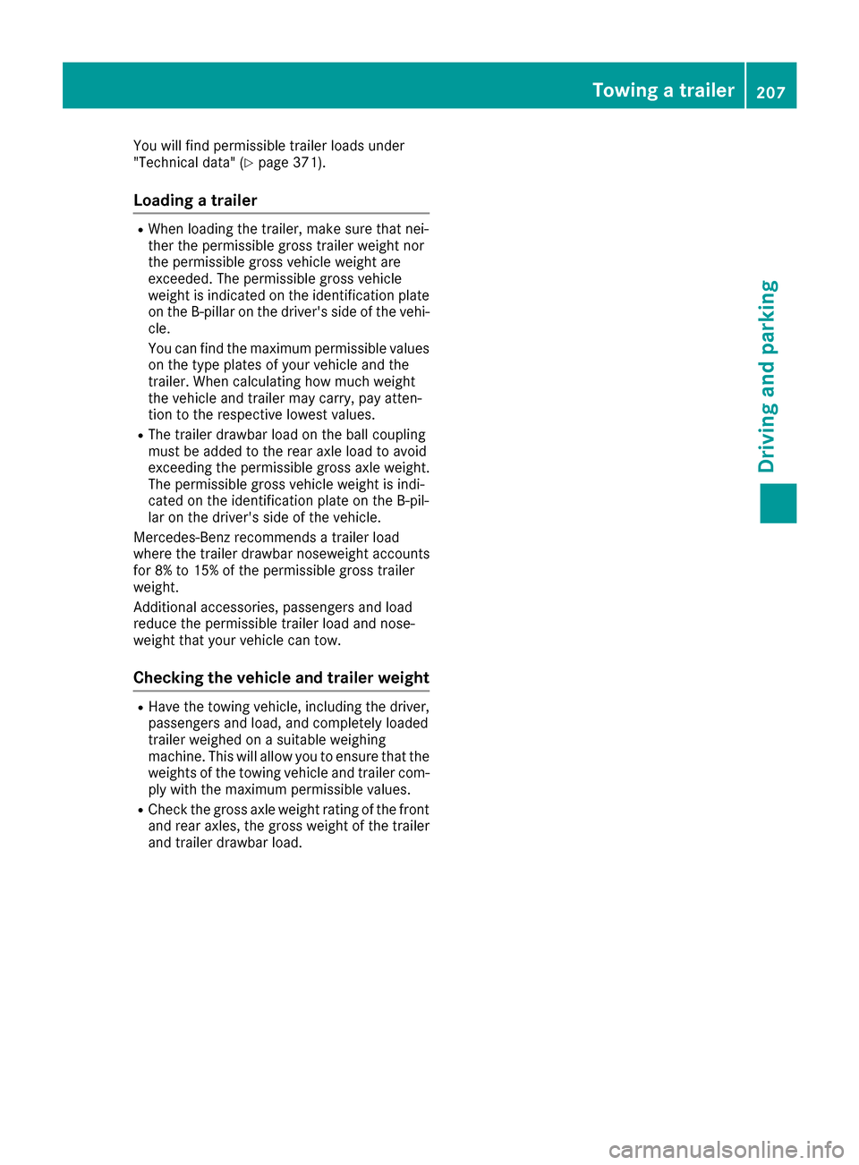
You will find permissible trailer loads under
"Technical data" (Ypage 371).
Loading a trailer
RWhen loading the trailer, make sure that nei-
ther the permissible gross trailer weight nor
the permissible gross vehicle weight are
exceeded. The permissible gross vehicle
weight is indicated on the identification plate
on the B-pillar on the driver's side of the vehi-
cle.
You can find the maximum permissible valueson the type plates of your vehicle and the
trailer. When calculating how much weight
the vehicle and trailer may carry, pay atten-
tion to the respective lowest values.
RThe trailer drawbar load on the ball coupling
must be added to the rear axle load to avoid
exceeding the permissible gross axle weight.
The permissible gross vehicle weight is indi-
cated on the identification plate on the B-pil-
lar on the driver's side of the vehicle.
Mercedes-Benz recommends a trailer load
where the trailer drawbar noseweight accounts
for 8% to 15% of the permissible gross trailer
weight.
Additional accessories, passengers and load
reduce the permissible trailer load and nose-
weight that your vehicle can tow.
Checking the vehicle and trailer weight
RHave the towing vehicle, including the driver,
passengers and load, and completely loaded
trailer weighed on a suitable weighing
machine. This will allow you to ensure that the
weights of the towing vehicle and trailer com-
ply with the maximum permissible values.
RCheck the gross axle weight rating of the front
and rear axles, the gross weight of the trailer
and trailer drawbar load.
Towing a trailer207
Driving and parking
Z
Page 289 of 374

an accident. There is a risk of injury, particu-
larly in the event of sharp braking or sudden
changes of direction.
RAlways stow objects in such a way that theycannot be tossed about in these or similar
situations.
RAlways make sure that objects do not pro-
trude out of the stowage spaces, luggage
nets or stowage nets.
REnsure that closable stowage spaces are
shut before beginning your journey.
RAlways stow and secure heavy, hard, poin-
ted, sharp-edged, fragile or large objects in
the cargo compartment.
Observe the following notes:
RObserve the loading guidelines (Ypage 278).
RTo avoid damaging the side trim panels in the
cargo compartment, maintain a sufficient dis-
tance from the side trim panels in the cargo
compartment when removing and inserting
the cargo compartment floor.
Installing the parcel net
XOpen cargo compartment floor ;
(Ypage 288), raise by approximately 45° and
remove to the rear.
XPlace cargo compartment floor ;on a clean
surface.
XStretch parcel net :over cargo compart-
ment floor ;as shown.
Make sure that:
Rparcel net :is aligned with the center of
cargo compartment floor ;
Rrubber band=is below mountings ?
RtabAis facing forward
XSlide cargo compartment floor ;horizon-
tally into the cargo compartment until mount-
ings ?are positioned in guides Eon both
sides.
XRaise cargo compartment floor ;by approx-
imately 45° so that mountings ?engage
audibly.
Make sure that:
Rrubber band Cis below clasp B. The rubber
band must not block the clasp.
Rrubber band =is below base D.
XFold cargo compartment floor ;down and
press down until it engages.
Coat hooks on the tailgate
:Coat hook
Cargo compartment plug-in module
(telescope bars)
General notes
The cargo compartment plug-in module allows
you to use your cargo compartment for a variety
of purposes.
Stowage areas287
Stowage and features
Z
Page 325 of 374

!Do not operate the tire inflation compressor
for longer than ten minutes at a time without
a break. It may otherwise overheat.
The tire inflation compressor can be operated
again once it has cooled down.
Comply with the manufacturer’s safety instruc-
tions on the sticker on the tire inflation com-
pressor.
Using the TIREFIT kit
XDo not remove any foreign objects which have
penetrated the tire, e.g. screws or nails.
XRemove the tire sealant bottle, the accompa-
nying TIREFIT sticker and the tire inflation
compressor from the stowage well under-
neath the cargo compartment floor
(
Ypage 320).
XAffix part :of the TIREFIT sticker to the
instrument cluster within the driver's field of
vision.
XAffix part ;of the TIREFIT sticker near the
valve on the wheel with the defective tire.
XPull connector ?with cable and hose Aout
of the tire inflation compressor housing.
XPush connector on hose Ainto flange Bon
tire sealant bottle :until the connector
engages.
XPlace tire sealant bottle :head down into
recess ;of the tire inflation compressor.
XRemove the cap from valve Con the faulty
tire.
XScrew filler hose Donto valve C.
XInsert plug ?into cigarette lighter socket
(Ypage 292) or into another 12 V socket in
your vehicle (Ypage 293).
XTurn the SmartKey to position 1in the igni-
tion lock (Ypage 132).
XPress on and off switch =on the tire inflation
compressor.
The tire inflation compressor is switched on.
The tire is inflated.
First, tire sealant is pumped into the tire. The
pressure may briefly rise to approximately
500 kPa (5 bar/73 psi).
Do not switch off the tire inflation com-
pressor during this phase.
XLet the tire inflation compressor run for a
maximum of ten minutes. The tire should then
have attained a pressure of at least 200 kPa
(2.0 bar/29 psi).
If a pressure of 200 kPa (2.0 bar/29 psi) has
been attained after five minutes, see "Tire pres-
sure reached" (
Ypage 324).
If a tire pressure of 200 kPa (2.0 bar/29 psi) has
not been attained after five minutes, see "Tire
pressure not reached" (
Ypage 324).
If tire sealant has escaped, clean it off affected
areas as quickly as possible. Use plain water if
possible.
Flat tire323
Breakdown assistance
Z
Page 326 of 374

If your clothes are soiled with tire sealant, have
them cleaned with perchloroethylene at a dry
cleaner as soon as possible.
Tire pressure not reached
If a tire pressure of 200 kPa (2.0 bar/29 psi) has
not been attained after ten minutes:
XSwitch off the tire inflation compressor.
XUnscrew the filler hose from the valve of the
faulty tire.
Tire sealant may escape when the filler hose is
unscrewed.
XVery slowly drive forwards or reverse approx-imately 30 ft (10 m).
XPump up the tire again.
After a maximum of ten minutes, the tire pres-
sure must be at least 200 kPa (2.0 bar/
29 psi).
GWARNING
If the required tire pressure is not reached
after the specified time, the tire is too badly
damaged. The tire sealant cannot repair the
tire in this instance. Damaged tires and a tire
pressure that is too low can significantly
impair the vehicle's braking and driving char-
acteristics. There is a risk of accident.
Do not continue driving. Contact a qualified
specialist workshop.
Tire pressure reached
GWARNING
A tire temporarily sealed with tire sealant
impairs the driving characteristics and is not
suitable for higher speeds. There is a risk of
accident.
You should therefore adapt your driving style
accordingly and drive carefully. Do not exceed the specified maximum speed with a tire that
has been repaired using tire sealant.
The maximum permissible speed for a tire
sealed with tire sealant is 50 mph (80 km/h).
The upper part of the TIREFIT sticker must be
affixed to the instrument cluster in the driver's
field of vision. If a tire pressure of 200 kPa (2.0 bar/29 psi) has
been attained after ten minutes:
XSwitch off the tire inflation compressor.
XUnscrew the filler hose from the valve of the
faulty tire.
Tire sealant may escape when the filler hose is
unscrewed.
XStow the tire sealant bottle and the tire infla-
tion compressor.
XPull away immediately
.
XStop after driving for approximately ten
minutes and check the tire pressure with the
tire inflation compressor.
The tire pressure must now be at least
130 kPa (1.3 bar/19 psi).
GWARNING
If the required tire pressure is not reached
after driving for a short period, the tire is too
badly damaged. The tire sealant cannot repair
the tire in this instance. Damaged tires and a
tire pressure that is too low can significantly
impair the vehicle's braking and driving char-
acteristics. There is a risk of accident.
Do not continue driving. Contact a qualified
specialist workshop.
In cases such as the one mentioned above, con- tact an authorized Mercedes-Benz Center. Or
call 1-800-FOR-MERCedes (in the USA) or
1-800-387-0100 (in Canada).
XCorrect the tire pressure if it is still at least
130 kPa (1.3 bar/19 psi). See the Tire and
Loading Information placard on the B-pillar on
the driver's side or the tire pressure table in
the fuel filler flap for values.
XTo increase the tire pressure: switch on the
tire inflation compressor.
324Flat tire
Breakdown assistance
Page 332 of 374

XSlide coverAof positive terminal :in the direction of the arrow.
XConnect positive terminal :on your vehicle to positive terminal ;of donor battery Busing the
jumper cable, Always begin with positive terminal :on your own vehicle first.
XStart the engine of the donor vehicle and run it at idling speed.
XConnect negative terminal =of donor battery Cto ground point ?of your vehicle using the
jumper cable, connecting the jumper cable to battery of other vehicle Bfirst.
XStart the engine.
XBefore disconnecting the jumper cables, let the engine run for several minutes.
XFirst, remove the jumper cables from ground point ?and negative terminal =, then from pos-
itive clamp :and positive terminal ;. Begin each time at the contacts on your own vehicle first.
XClose coverAof positive terminal :after removing jumper cables.
XHave the battery checked at a qualified specialist workshop.
Jump-starting is not considered to be a normal operating condition.
iJumper cables and further information regarding jump-starting can be obtained at any qualified
specialist workshop.
Towing and tow-starting
Important safety notes
GWARNING
Functions relevant to safety are restricted or
no longer available if:
Rthe engine is not running.
Rthe brake system or the power steering is
malfunctioning.
Rthere is a malfunction in the voltage supply or the vehicle's electrical system.
If your vehicle is being towed, much more
force may be necessary to steer or brake.
There is a risk of an accident.
In such cases, use a tow bar. Before towing,
make sure that the steering moves freely.
GWARNING
You can no longer steer the vehicle if the
steering wheel lock has been engaged. There
is a risk of an accident.
Always switch off the ignition when towing the
vehicle with a tow cable or a tow bar.
GWARNING
When towing or tow-starting another vehicle
and its weight is greater than the permissible
gross weight of your vehicle, the:
Rthe towing eye could detach itself
Rthe vehicle/trailer combination could roll-
over.
There is a risk of an accident.
When towing or tow-starting another vehicle,
its weight should not be greater than the per- missible gross weight of your vehicle.
Details on the permissible gross vehicle weight
of your vehicle can be found on the vehicle iden-
tification plate (
Ypage 363).
!When Active Brake Assist, Distance Pilot
DISTRONIC or the HOLD function is activated,
the vehicle brakes automatically in certain
situations.
To avoid damage to the vehicle, deactivate
these systems in the following or similar sit-
uations:
Rwhen towing the vehicle
Rin the car wash
!Make sure that the electric parking brake is
released. If the electric parking brake is faulty,
visit a qualified specialist workshop.
!Only secure the tow rope or tow bar at the
towing eyes, or the trailer tow hitch, if availa-
ble. You could otherwise damage the vehicle.
330Towing and tow-starting
Breakdown assistance
Page 334 of 374

XRemove thetowin geye from th eretainer
(Ypage 320).
XMercedes-AM Gvehicles: useasuitable
object, e.g. ascrewdriver, to pry off cover :
on th efron tbumper from underneath. Tak e
th ecover from th eopening ,but do no t
remove it .
Press th emar kon cover :on th erear
bumper inward and remove .
XAll other vehicles:press themar kon
cover :inward and remove .
XScrew in thetowin geye clockwise as far as it
will go and tighten it .
Vehicles wit h atrailer to whitch do no thav e a
bracke tfor th escrew-in towin geye at th eback.
Connect th etowbar to th etrailer to whitch
(
Ypage 204).
Removing the towing eye
XUnscrew and remove th etowin geye.
XAttac hcover :to th ebumper and press until
it engages.
Towing a vehicle with both axles on
the ground
The automatic transmission automatically shifts
to position jwhen you open th edriver' sor
front-passenger door or when you remove th e
SmartKey from th eignition lock. It is essential to
observ eth efollowin gsteps to ensur ethat th e
automatic transmission remain sin position i
during towing.
XMak esur ethat th evehicl eis stationary.
XTurn th eSmartKey to position 2in th eigni-
tion lock.
XDepress and hold th ebrak epedal .
XShift th eautomatic transmission to position
i.
XLeav eth eSmartKey in position 2in th eigni-
tion lock.
XReleas eth ebrak epedal .
XReleas eth eelectric parking brake.
XSwitc hon th ehazard warning lamp s
(Ypage 113).
In order to signal achang eof direction when
towin gth evehicl ewit hth ehazard warning
lamp sswitched on ,use th ecombination switch
as usual. In this case, only th eindicator lamp sfor th
edirection of travel flash. Afte rresetting
th ecombination switch ,th ehazard warning
lamp start sflashin gagain .
Transporting the vehicle
General notes
!When th evehicl eis loade dfor transport, th e
fron tand rear axles mus tbe stationary and on
th esam etransportation vehicle. Positioning
ove rth econnection poin tof th etranspor t
vehicl eis no tpermitted. The driv etrain may
otherwise be damaged.
!You may only secure th evehicl eby th e
wheels, no tby part sof th evehicl esuc has
axl eor steering components. Otherwise, th e
vehicl ecould be damaged.
The towin geye or trailer to whitch can be used
to pull th evehicl eonto atrailer or transporte rif
you wish to transpor tit.
XTurn th eSmartKey to position 2in th eigni-
tion lock.
XShift th eautomatic transmission to position
i.
As soon as th evehicle ha sbeen loaded:
XPreven tth evehicl efrom rollin gaway by
applyin gth eelectric parking brake.
XShift th eautomatic transmission to position
j.
XTurn th eSmartKey to position uin th eigni-
tion loc kand remove it .
XSecureth evehicle.
332Towing and tow-starting
Breakdown assistance
Page 362 of 374

Lowering the vehicle
GWARNING
The wheels could work loose if the wheel nuts and bolts are not tightened to the specified
tightening torque. There is a risk of accident.
Have the tightening torque immediately
checked at a qualified specialist workshop
after a wheel is changed.
XPlace the ratchet wrench onto the hexagon
nut of the jack so that the letters ABare visi-
ble.
XTurn the ratchet wrench until the vehicle is
once again standing firmly on the ground.
XPlace the jack to one side.
XTighten the wheel bolts evenly in a crosswise pattern in the sequence indicated (: toA).
The specified tightening torque is 96 lb-ft
(130 Nm) .
XTurn the jack back to its initial position.
XStow the jack and the rest of the tire-change
tool kit in the cargo compartment again.
XCheck the tire pressure of the newly mounted
wheel and adjust it if necessary.
Observe the recommended tire pressure
(
Ypage 339).
When you are driving with the collapsible spare wheel mounted, the tire pressure loss warning
system or the tire pressure monitor cannot func-
tion reliably. Only restart the tire pressure loss
warning system or tire pressure monitor when
the defective wheel has been replaced with a
new wheel.
Vehicles with a tire pressure control sys-
tem: all installed wheels must be equipped with
functioning sensors.
Wheel/tire combination
You can ask for information regarding permitted wheel/tire combinations at an authorized
Mercedes-Benz Center.
!For safety reasons, Mercedes-Benz recom-
mends that you only use tires and wheels
which have been approved by Mercedes-Benz
specifically for your vehicle.
These tires have been specially adapted for
use with the control systems, such as ABS or
ESP
®, and are marked as follows:
RMO = Mercedes-Benz Original
RMOE = Mercedes-Benz Original Extended
(tires featuring run-flat characteristics)
RMO1 = Mercedes-Benz Original (only cer-
tain AMG tires)
Mercedes-Benz Original Extended tires may
only be used on wheels that have been spe-
cifically approved by Mercedes-Benz.
Only use tires, wheels or accessories tested
and approved by Mercedes-Benz. Certain
characteristics, e.g. handling, vehicle noise
emissions or fuel consumption, may other-
wise be adversely affected. In addition, when
driving with a load, tire dimension variations
could cause the tires to come into contact
with the bodywork and axle components. This
could result in damage to the tires or the vehi- cle.
Mercedes-Benz accepts no liability for dam-
age resulting from the use of tires, wheels or
accessories other than those tested and
approved.
Information on tires, wheels and approved
combinations can be obtained from any quali-
fied specialist workshop.
!Retreaded tires are neither tested nor rec-
ommended by Mercedes-Benz, since previ-
ous damage cannot always be detected on
retreaded tires. As a result, Mercedes-Benz
cannot guarantee vehicle safety if retreaded
tires are mounted. Do not mount used tires if
you have no information about their previous
usage.
The recommended pressures for various oper-
ating conditions can be found:
Ron the Tire and Loading Information placard
on the B-pillar on the driver's side
Rin the tire pressure table in the fuel filler flap
360Wheel/tire combination
Wheels and tires
Page 373 of 374
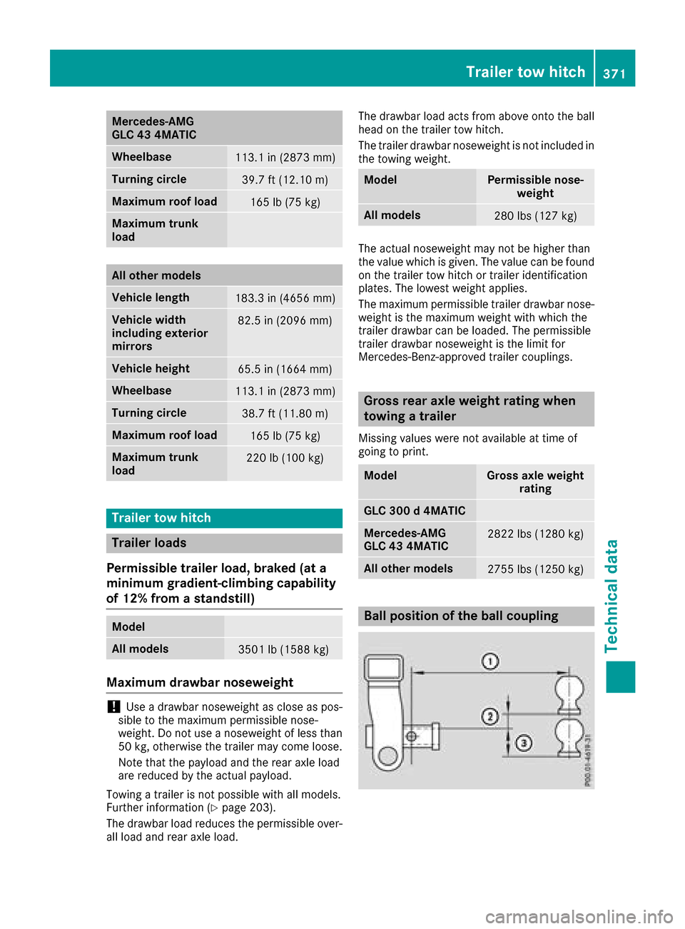
Mercedes-AMG
GLC 43 4MATIC
Wheelbase113.1 in (2873 mm)
Turning circle39.7 ft (12.10m)
Maximum roof load165 lb (75 kg)
Maximum trunk
load
All other models
Vehicle length183.3 in (4656 mm)
Vehicle width
including exterior
mirrors82.5 in (2096 mm)
Vehicle height65.5 in (1664 mm)
Wheelbase113.1 in (2873 mm)
Turning circle38.7 ft (11.80m)
Maximum roof load165 lb (75 kg)
Maximum trunk
load220 lb (100 kg)
Trailer tow hitch
Trailer loads
Permissible trailer load, braked (at a
minimum gradient-climbing capability
of 12% from a standstill)
Model
All models3501 lb (1588 kg)
Maximum drawbar noseweight
!Use a drawbar noseweight as close as pos-
sible to the maximum permissible nose-
weight. Do not use a noseweight of less than
50 kg, otherwise the trailer may come loose.
Note that the payload and the rear axle load
are reduced by the actual payload.
Towing a trailer is not possible with all models.
Further information (
Ypage 203).
The drawbar load reduces the permissible over-
all load and rear axle load. The drawbar load acts from above onto the ball
head on the trailer tow hitch.
The trailer drawbar noseweight is not included in
the towing weight.
ModelPermissible nose-
weight
All models280 lbs (127 kg)
The actual noseweight may not be higher than
the value which is given. The value can be found
on the trailer tow hitch or trailer identification
plates. The lowest weight applies.
The maximum permissible trailer drawbar nose-
weight is the maximum weight with which the
trailer drawbar can be loaded. The permissible
trailer drawbar noseweight is the limit for
Mercedes-Benz-approved trailer couplings.
Gross rear axle weight rating when
towing a trailer
Missing values were not available at time of
going to print.
ModelGross axle weight rating
GLC 300 d 4MATIC
Mercedes-AMG
GLC 43 4MATIC2822 lbs (1280 kg)
All other models2755 lbs (1250 kg)
Ball position of the ball coupling
Trailer tow hitch371
Technical data
Z