emergency towing MERCEDES-BENZ GLE 2016 Owners Manual
[x] Cancel search | Manufacturer: MERCEDES-BENZ, Model Year: 2016, Model line: GLE, Model: MERCEDES-BENZ GLE 2016Pages: 450, PDF Size: 12.92 MB
Page 6 of 450
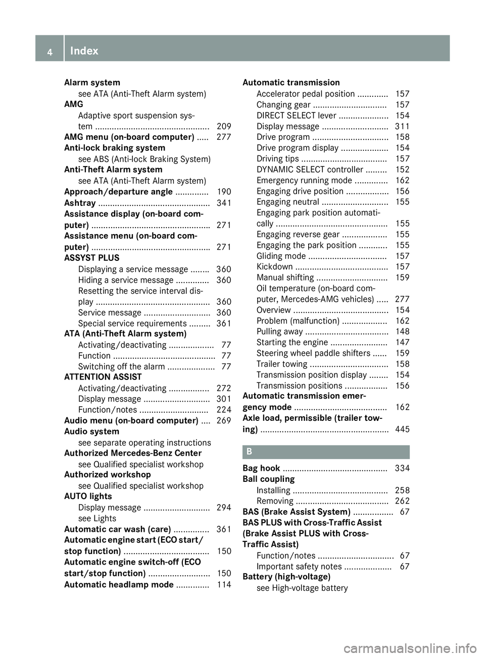
Alarm system
see ATA (Anti-Theft Alarm system)
AMG
Adaptive sport suspension sys-
tem ................................................ 209
AMG menu (on-board computer) .... .2 77
Anti-lock braking system
see ABS (Anti-lock Braking System)
Anti-Theft Alarm system
see ATA (Anti-Theft Alarm system)
Approach/departure angle .............. 190
Ashtray ............................................... 341
Assistance display (on-board com-
puter) ................................................. .2 71
Assistance menu (on-board com-
puter) ................................................. .2 71
ASSYST PLUS
Displaying a service message ....... .3 60
Hiding a service message .............. 360
Resetting the service interval dis-
play ................................................ 360
Service message ............................ 360
Special service requirements ......... 361
ATA (Anti-Theft Alarm system)
Activating/deactivating ................... 77
Function .......................................... .7 7
Switching off the alarm .................... 77
ATTENTION ASSIST
Activating/deactivating ................. 272
Display message ............................ 301
Function/notes ............................. 224
Audio menu (on-board computer) .... 269
Audio system
see separate operating instructions
Authorized Mercedes-Benz Center
see Qualified specialist workshop
Authorized workshop
see Qualified specialist workshop
AUTO lights
Display message ............................ 294
see Lights
Automatic car wash (care) ............... 361
Automatic engine start (ECO start/
stop function) .................................... 150
Automatic engine switch-off (ECO
start/stop function) .......................... 150
Automatic headlamp mode .............. 114 Automatic transmission
Accelerato r pedal position ............. 157
C hanging gear ............................... 157
DIRECT SELECT lever ..................... 154
Display message ............................ 311
Drive program ................................ 158
Drive program display .................... 154
Driving tips .................................... 157
DYNAMIC SELECT controller ......... 152
Emergency running mode .............. 162
Engaging drive position .................. 156
Engaging neutral ............................ 155
Engaging park position automati-
cally ............................................... 155
Engaging reverse gear ................... 155
Engaging the park position ............ 155
Gliding mode ................................. 157
Kickdown ....................................... 157
Manual shifting .............................. 159
Oil temperature (on-board com-
puter, Mercedes-AMG vehicles) ..... 277
Overview ........................................ 154
Problem (malfunction) ................... 162
Pulling away ................................... 148
Starting the engine ........................ 147
Steering wheel paddle shifters ...... 159
Trailer towing ................................. 158
Transmission position display ........ 154
Transmission positions .................. 156
Automatic transmission emer-
gency mode ....................................... 162
Axle load, permissible (trailer tow-
ing) ...................................................... 445
B
Bag hook ............................................ 334
Ball coupling
Installing ........................................ 258
Removing ....................................... 262
BAS (Brake Assist System) ................. 67
BAS PLUS with Cross-Traffic Assist
(Brake Assist PLUS with Cross-
Traffic Assist)
Function/notes ................................ 67
Important safety notes .................... 67
Battery (high-voltage)
see High-voltage battery4
Index
Page 11 of 450
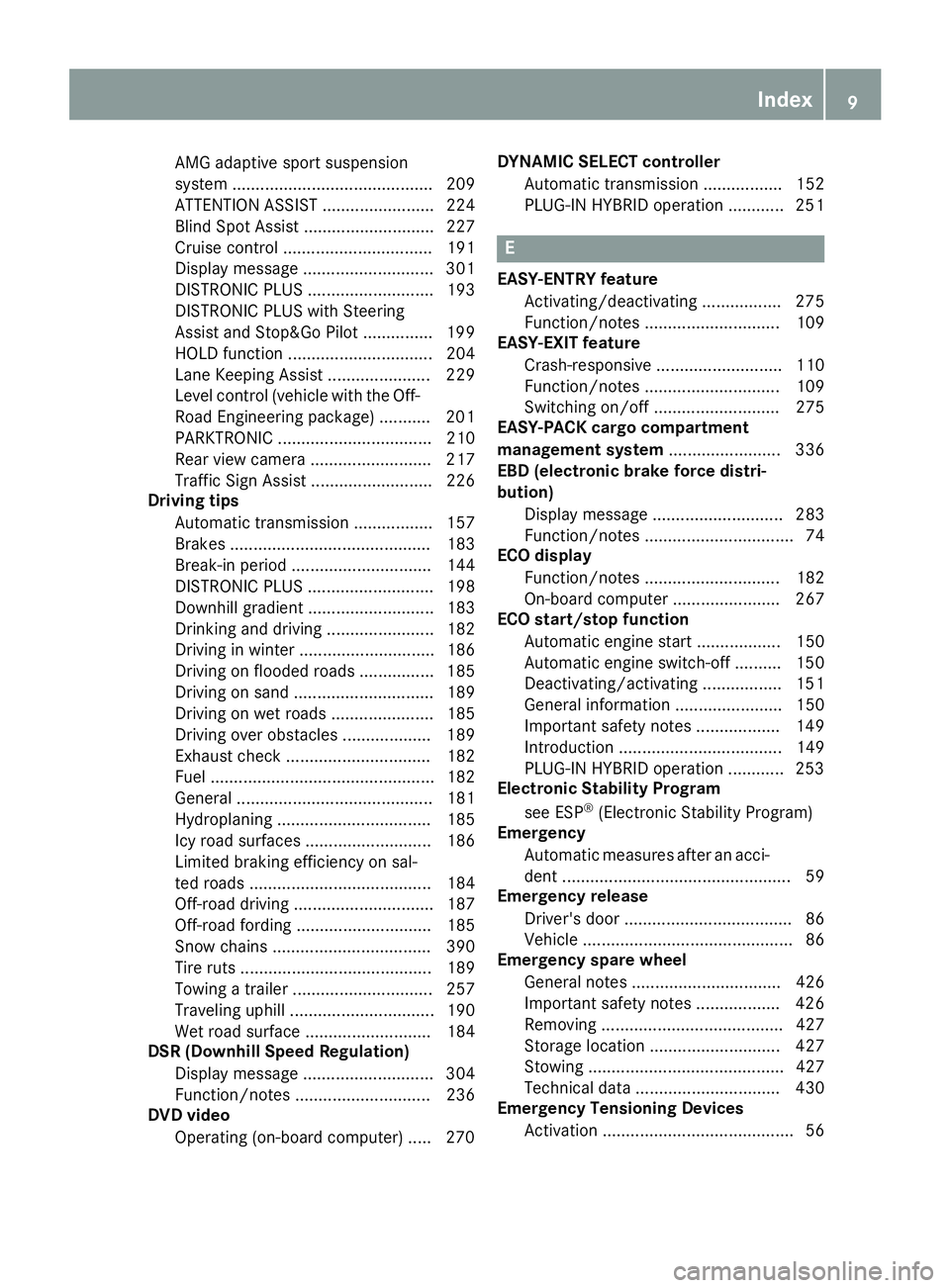
AMG adaptive sport suspension
system ........................................... 209
ATTENTION ASSIST ........................ 224
Blind Spot Assist ............................ 227
Cruise control ................................ 191
Display message ............................ 301
DISTRONIC PLUS ........................... 193
DISTRONIC PLUS with Steering
Assist and Stop&Go Pilot ............... 199
HOLD function ............................... 204
Lane Keeping Assist ...................... 229
Level control (vehicle with the Off-
Road Engineering package) ........... 201
PARKTRONIC ................................. 210
Rear view camera .......................... 217
Traffic Sign Assist .......................... 226
Driving tips
Automatic transmission ................. 157
Brakes ........................................... 183
Break-in period .............................. 144
DISTRONIC PLUS ........................... 198
Downhill gradient ........................... 183
Drinking and driving ....................... 182
Driving in winter ............................. 186
Driving on flooded roads ................ 185
Driving on sand .............................. 189
Driving on wet roads ...................... 185
Driving over obstacles ................... 189
Exhaust check ............................... 182
Fuel ................................................ 182
General .......................................... 181
Hydroplaning ................................. 185
Icy road surfaces ........................... 186
Limited braking efficiency on sal-
ted roads ....................................... 184
Off-road driving .............................. 187
Off-road fording ............................. 185
Snow chains .................................. 390
Tire ruts ......................................... 189
Towing a trailer .............................. 257
Traveling uphill ............................... 190
Wet road surface ........................... 184
DSR (Downhill Speed Regulation)
Display message ............................ 304
Function/notes ............................. 236
DVD video
Operating (on-board computer) ..... 270 DYNAMIC SELECT controller
Automatic transmission ................. 152
PLUG-IN HYBRID operation ............ 251
E EASY-ENTRY feature
Activating/deactivating ................. 275
Function/notes ............................. 109
EASY-EXIT feature
Crash-responsive ........................... 110
Function/notes ............................. 109
Switching on/off ........................... 275
EASY-PACK cargo compartment
management system ........................ 336
EBD (electronic brake force distri-
bution)
Display message ............................ 283
Function/notes ................................ 74
ECO display
Function/notes ............................. 182
On-board computer ....................... 267
ECO start/stop function
Automatic engine start .................. 150
Automatic engine switch-off .......... 150
Deactivating/activating ................. 151
General information ....................... 150
Important safety notes .................. 149
Introduction ................................... 149
PLUG-IN HYBRID operation ............ 253
Electronic Stability Program
see ESP ®
(Electronic Stability Program)
Emergency
Automatic measures after an acci-
dent ................................................. 59
Emergency release
Driver's door .................................... 86
Vehicle ............................................. 86
Emergency spare wheel
General notes ................................ 426
Important safety notes .................. 426
Removing ....................................... 427
Storage location ............................ 427
Stowing .......................................... 427
Technical data ............................... 430
Emergency Tensioning Devices
Activation ......................................... 56 Index 9
Page 23 of 450
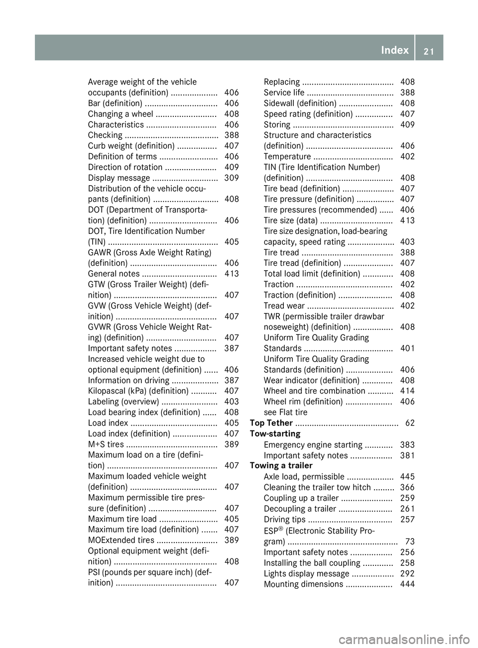
Average weight of the vehicle
occupants (definition) .................... 406
Bar (definition) ............................... 406
Changing a wheel .......................... 408
Characteristics .............................. 406
Checking ........................................ 388
Curb weight (definition) ................. 407
Definition of terms ......................... 406
Direction of rotation ...................... 409
Display message ............................ 309
Distribution of the vehicle occu-
pants (definition) ............................ 408
DOT (Department of Transporta-
tion) (definition) ............................. 406
DOT, Tire Identification Number
(TIN) ............................................... 405
GAWR (Gross Axle Weight Rating)
(definition) ..................................... 406
General notes ................................ 413
GTW (Gross Trailer Weight) (defi-
nition) ............................................ 407
GVW (Gross Vehicle Weight) (def-
inition) ........................................... 407
GVWR (Gross Vehicle Weight Rat-
ing) (definition) .............................. 407
Important safety notes .................. 387
Increased vehicle weight due to
optional equipment (definition) ...... 406
Information on driving .................... 387
Kilopascal (kPa) (definition) ........... 407
Labeling (overview) ........................ 403
Load bearing index (definition) ...... 408
Load index ..................................... 405
Load index (definition) ................... 407
M+S tires ....................................... 389
Maximum load on a tire (defini-
tion) ............................................... 407
Maximum loaded vehicle weight
(definition) ..................................... 407
Maximum permissible tire pres-
sure (definition) ............................. 407
Maximum tire load ......................... 405
Maximum tire load (definition) ....... 407
MOExtended tires .......................... 389
Optional equipment weight (defi-
nition) ............................................ 408
PSI (pounds per sq uare inch) (def-
i
nition) ........................................... 407 Replacing ....................................... 408
Service life ..................................... 388
Sidewall (definition) ....................... 408
Speed rating (definition) ................ 407
Storing ........................................... 409
Structure and characteristics
(definition) ..................................... 406
Temperature .................................. 402
TIN (Tire Identification Number)
(definition) ..................................... 408
Tire bead (definition) ...................... 407
Tire pressure (definition) ................ 407
Tire pressures (recommended) ...... 406
Tire size (data) ............................... 413
Tire size designation, load-bearing
capacity, speed rating .................... 403
Tire tread ....................................... 388
Tire tread (definition) ..................... 407
Total load limit (definition) ............. 408
Traction ......................................... 402
Traction (definition) ....................... 408
Tread wear ..................................... 402
TWR (permissible trailer drawbar
noseweight) (definition) ................. 408
Uniform Tire Quality Grading
Standards ...................................... 401
Uniform Tire Quality Grading
Standards (definition) .................... 406
Wear indicator (definition) ............. 408
Wheel and tire combination ........... 414
Wheel rim (definition) .................... 406
see Flat tire
Top Tether ............................................ 62
Tow-starting
Emergency engine starting ............ 383
Important safety notes .................. 381
Towing a trailer
Axle load, permissible .................... 445
Cleaning the trailer tow hitch ......... 366
Coupling up a trailer ...................... 259
Decoupling a trailer ....................... 261
Driving tips .................................... 257
ESP ®
(Electronic Stability Pro-
gram) ............................................... 73
Important safety notes .................. 256
Installing the ball coupling ............. 258
Lights display message .................. 292
Mo u nting dimensions .................... 444 Index 21
Page 24 of 450
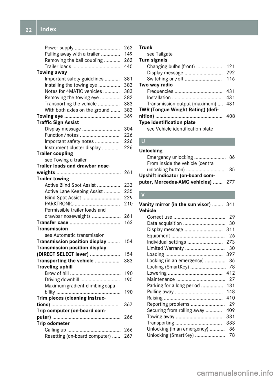
Power supply ................................. 262
Pulling away with a trailer .............. 149
Removing the ball coupling ............ 262
Trailer loads ................................... 445
Towing away
Important safety guidelines ........... 381
Installing the towing eye ............... .3 82
Notes for 4MATIC vehicles ............ 383
Removing the towing eye .............. .3 82
Transporting the vehicle ................ 383
With both axles on the ground ....... 382
Towing eye ......................................... 369
Traffic Sign Assist
Display message ............................ 304
Function/notes ............................ .2 26
Important safety notes .................. 226
Instrument cluster display ............. 226
Trailer coupling
see Towing a trailer
Trailer loads and drawbar nose-
weights ............................................... 261
Trailer towing
Active Blind Spot Assist ................. 233
Active Lane Keeping Assist ............ 235
Blind Spot Assist ............................ 229
PARKTRONIC ................................. 210
Permissible trailer loads and
drawbar noseweights ..................... 261
Transfer case ..................................... 162
Transmission
see Automatic transmission
Transmission position display ......... 154
Transmission position display
(DIRECT SELECT lever) ..................... .1 54
Transporting the vehicle .................. 383
Traveling uphill
Brow of hill ..................................... 190
Driving downhill ............................ .1 90
Maximum gradient-climbing capa-
bility ............................................... 190
Trim pieces (cleaning instruc-
tions) ................................................. .3 67
Trip computer (on-board com-
puter) ................................................. .2 66
Trip odometer
Calling up ....................................... 266
Resetting (on-board computer) ...... 267 Trunk
see Tailgate
Turn signals
Changing bul bs (front) ................... 121
Di spl ay message ............................ 292
Switching on/off ........................... 116
Two-way radio
Frequencies ................................... 431
Installation ..................................... 431
Transmission output (maximum) .... 431
TWR (Tongue Weight Rating) (defi-
nition) ................................................. 408
Type identification plate
see Vehicle identification plate
U Unlocking
Emergency unlocking ....................... 86
From inside the vehicle (central
unlocking button) ............................ .8 5
Upshift indicator (on-board com-
puter, Mercedes-AMG vehicles) ...... .2 77
V
Vanity mirror (in the sun visor) ....... .3 41
Vehicle
Correct use ...................................... 29
Data acquisition ............................... 30
Display message ............................ 311
Equipment ....................................... 26
Individual settings .......................... 273
Limited Warranty ............................ .3 0
Loading .......................................... 397
Locking (in an emergency) ............... 86
Locking (SmartKey) .......................... 78
Lowering ........................................ 412
Maintenance .................................... 27
Parking for a long period ................ 181
Pulling away ................................... 148
Raising ........................................... 410
Reporting problems ......................... 29
Securing from rolling away ............ 409
Towing away .................................. 381
Transporting .................................. 383
Unlocking (in an emergency) ........... 86
Unlocking (SmartKey) ...................... 7822
Index
Page 349 of 450
lished between the Customer Assistance Center
and the vehicle occupants. R
If the vehicle occupants respond, the
Mercedes-Benz Customer Assistance Center
attempts to get more information on the
emergency. R
If there is no response from the vehicle occu-
pants, an ambulance is immediately sent to
the vehicle.
If no voice connection can be established to the
Mercedes-Benz Customer Assistance Center,
the system has been unable to initiate an emer-
gency call.
This can occur, for example, if the relevant
mobile phone network is not available. The indi-
cator lamp in the SOS button flashes continu-
ously.
The Call Failed message appears in the mul-
tifunction display and must be confirmed.
In this case, summon assistance by other
means.
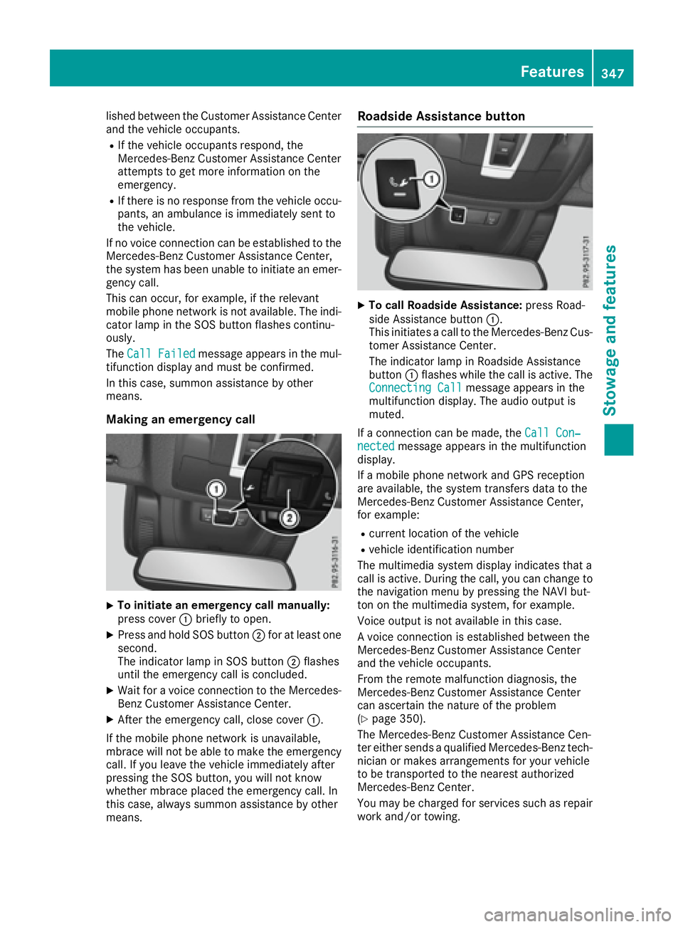
Making an emergency call
X
To initiate an emergency call manually:
press cover �C briefly to open.X
Press and hold SOS button �D for at least one
second.
The indicator lamp in SOS button �D flashes
until the emergency call is concluded. X
Wait for a voice connection to the Mercedes-
Benz Customer Assistance Center. X
After the emergency call, close cover �C .
If the mobile phone network is unavailable,
mbrace will not be able to make the emergency
call. If you leave the vehicle immediately after
pressing the SOS button, you will not know
whether mbrace placed the emergency call. In
this case, always summon assistance by other
means. Roadside Assistance button X
To call Roadside Assistance: press Road-
side Assistance button �C .
This initiates a call to the Mercedes-Benz Cus-
tomer Assistance Center.
The indicator lamp in Roadside Assistance
button �C flashes while the call is active. The
Connecting Call message appears in the
multifunction display. The audio output is
muted.
If a connection can be made, the Call Con‐
nected message appears in the multifunction
display.
If a mobile phone network and GPS reception
are available, the system transfers data to the
Mercedes-Benz Customer Assistance Center,
for example: R
current location of the vehicle R
vehicle identification number
The multimedia system display indicates that a
call is active. During the call, you can change to
the navigation menu by pressing the NAVI but-
ton on the multimedia system, for example.
Voice output is not available in this case.
A voice connection is established between the
Mercedes-Benz Customer Assistance Center
and the vehicle occupants.
From the remote malfunction diagnosis, the
Mercedes-Benz Customer Assistance Center
can ascertain the nature of the problem
( Y
page 350).
The Mercedes-Benz Customer Assistance Cen-
ter either sends a qualified Mercedes-Benz tech-
nician or makes arrangements for your vehicle
to be transported to the nearest authorized
Mercedes-Benz Center.
You may be charged for services such as repair
work and/or towing. Features 347
Stowage and features Z
Page 385 of 450
In order to ensure that the automatic transmis-
sion stays in position N when towing the vehicle,
you must observe the following points: X
Make sure that the vehicle is stationary. X
Turn the SmartKey to position 2 in the ignition
lock. X
Depress and hold the brake pedal. X
Shift the automatic transmission to position
N . X
Leave the SmartKey in position 2 in the igni-
tion lock. X
Release the brake pedal. X
Release the electric parking brake. X
Switch on the hazard warning lamps
( Y
page 116).
In order to signal a change of direction when
towing the vehicle with the hazard warning
lamps switched on, use the combination switch
as usual. In this case, only the indicator lamps
for the direction of travel flash. After resetting
the combination switch, the hazard warning
lamp starts flashing again.
Transporting the vehicle
PLUG-IN HYBRID vehicles Transportation of the vehicle should only be car-
ried out by professional recovery companies.
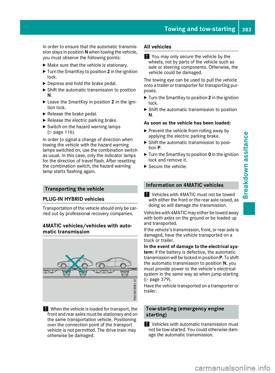
4MATIC vehicles/vehicles with auto-
matic transmission
! When the vehicle is loaded for transport, the
front and rear axles must be stationary and on
the same transportation vehicle. Positioning
over the connection point of the transport
vehicle is not permitted. The drive train may
otherwise be damaged. All vehicles
! You may only secure the vehicle by the
wheels, not by parts of the vehicle such as
axle or steering components. Otherwise, the
vehicle could be damaged.
The towing eye can be used to pull the vehicle
onto a trailer or transporter for transporting pur-
poses. X
Turn the SmartKey to position 2 in the ignition
lock. X
Shift the automatic transmission to position
N .
As soon as the vehicle has been loaded: X
Prevent the vehicle from rolling away by
applying the electric parking brake. X
Shift the automatic transmission to posi-
tion P . X
Turn the SmartKey to position 0 in the ignition
lock and remove it. X
Secure the vehicle.
Information on 4MATIC vehicles
! Vehicles with 4MATIC must not be towed
with either the front or the rear axle raised, as
doing so will damage the transmission.
Vehicles with 4MATIC may either be towed away
with both axles on the ground or be loaded up
and transported.
If the vehicle's transmission, front, or rear axle is
damaged, have the vehicle transported on a
truck or trailer.
In the event of damage to the electrical sys-
tem: if the battery is defective, the automatic
transmission will be locked in position P . To shift
the automatic transmission to position N , you
must provide power to the vehicle's electrical
system in the same way as when jump-starting
( Y
page 379).
Have the vehicle transported on a transporter or
trailer.
Tow-starting (emergency engine
starting)
! Vehicles with automatic transmission must
not be tow-started. You could otherwise dam-
age the automatic transmission.Towing and tow-starting 383
Breakdown assitance Z
Page 429 of 450
Removing/stowing the emergency
spare wheel
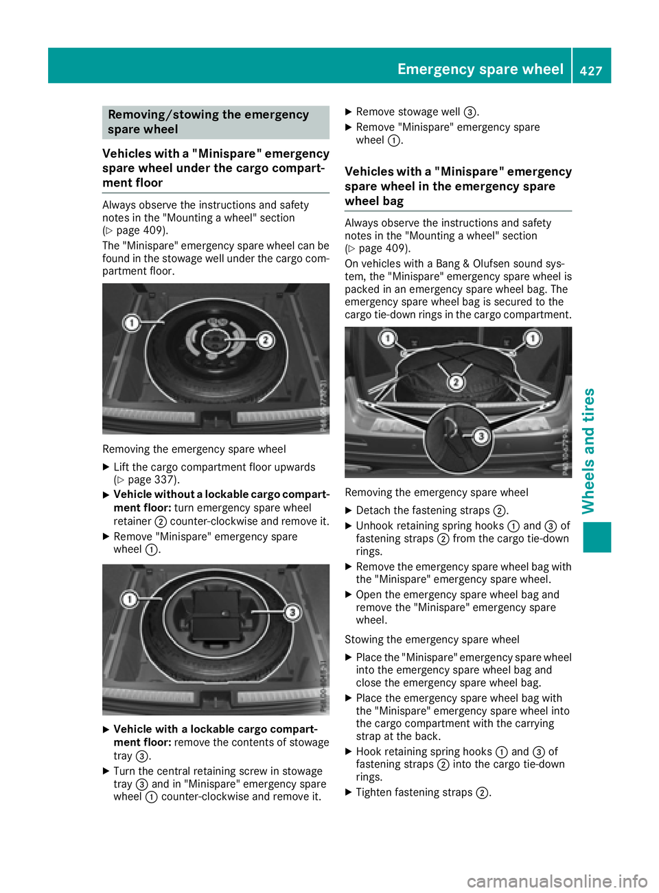
Vehicles with a "Minispare" emergency
spare wheel under the cargo compart-
ment floor Always observe the instructions and safety
notes in the "Mounting a wheel" section
( Y
page 409).
The "Minispare" emergency spare wheel can be
found in the stowage well under the cargo com-
partment floor.
Removing the emergency spare wheel X
Lift the cargo compartment floor upwards
( Y
page 337). X
Vehicle without a lockable cargo compart-
ment floor: turn emergency spare wheel
retainer �D counter-clockwise and remove it.X
Remove "Minispare" emergency spare
wheel �C .
X
Vehicle with a lockable cargo compart-
ment floor: remove the contents of stowage
tray �
Page 430 of 450
Mercedes-AMG vehicles with a collaps-
ible spare wheel under the cargo com-
partment floor
! Only place the collapsible spare wheel in the
vehicle when it is dry. Otherwise, moisture
may get into the vehicle.
Always observe the instructions and safety
notes in the "Mounting a wheel" section
( Y
page 409).
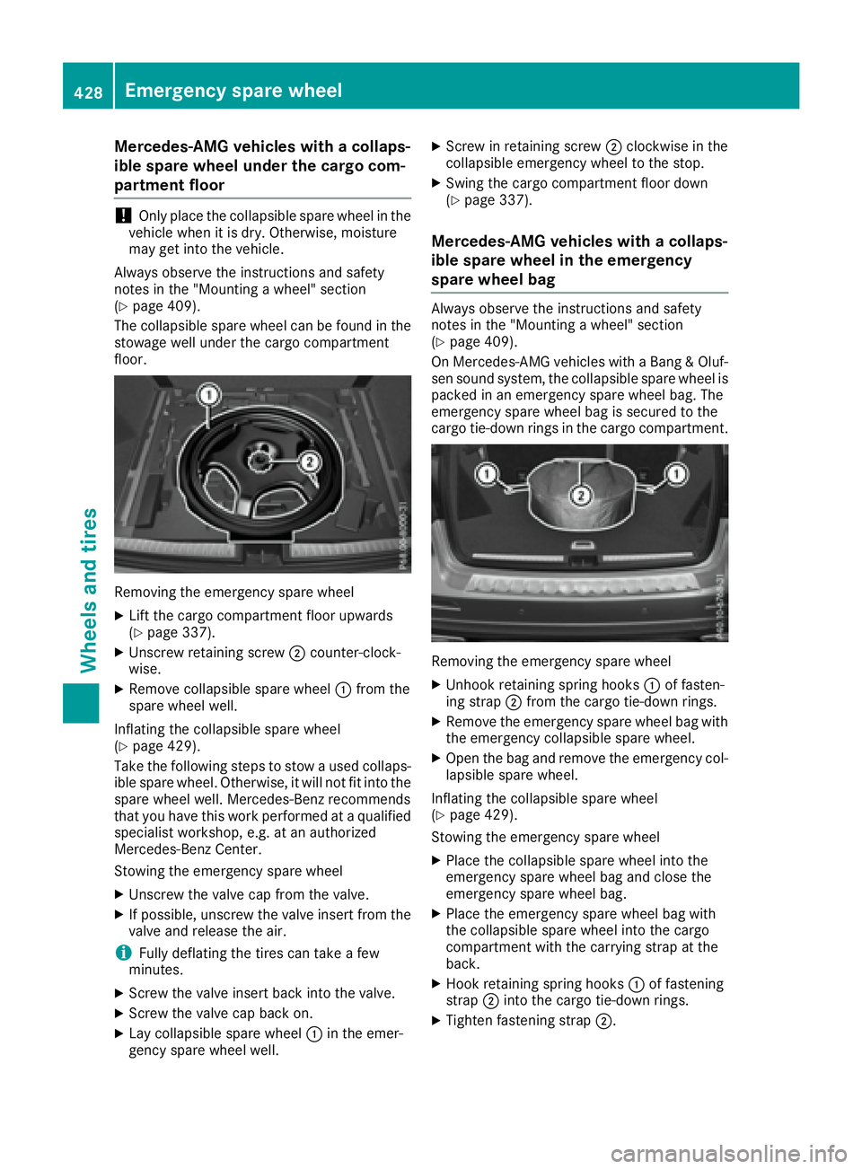
The collapsible spare wheel can be found in the
stowage well under the cargo compartment
floor.
Removing the emergency spare wheel X
Lift the cargo compartment floor upwards
( Y
page 337).X
Unscrew retaining screw �D counter-clock-
wise. X
Remove collapsible spare wheel �C from the
spare wheel well.
Inflating the collapsible spare wheel
( Y
page 429).
Take the following steps to stow a used collaps-
ible spare wheel. Otherwise, it will not fit into the
spare wheel well. Mercedes-Benz recommends
that you have this work performed at a qualified
specialist workshop, e.g. at an authorized
Mercedes-Benz Center.
Stowing the emergency spare wheel X
Unscrew the valve cap from the valve. X
If possible, unscrew the valve insert from the
valve and release the air.
i Fully deflating the tires can take a few
minutes. X
Screw the valve insert back into the valve. X
Screw the valve cap back on. X
Lay collapsible spare wheel �C in the emer-
gency spare wheel well. X
Screw in retaining screw �D clockwise in the
collapsible emergency wheel to the stop. X
Swing the cargo compartment floor down
( Y
page 337).
Mercedes-AMG vehicles with a collaps-
ible spare wheel in the emergency
spare wheel bag Always observe the instructions and safety
notes in the "Mounting a wheel" section
( Y
page 409).
On Mercedes-AMG vehicles with a Bang & Oluf-
sen sound system, the collapsible spare wheel is
packed in an emergency spare wheel bag. The
emergency spare wheel bag is secured to the
cargo tie-down rings in the cargo compartment.
Removing the emergency spare wheel X
Unhook retaining spring hooks �C of fasten-
ing strap �D from the cargo tie-down rings. X
Remove the emergency spare wheel bag with
the emergency collapsible spare wheel. X
Open the bag and remove the emergency col-
lapsible spare wheel.
Inflating the collapsible spare wheel
( Y
page 429).
Stowing the emergency spare wheel X
Place the collapsible spare wheel into the
emergency spare wheel bag and close the
emergency spare wheel bag. X
Place the emergency spare wheel bag with
the collapsible spare wheel into the cargo
compartment with the carrying strap at the
back. X
Hook retaining spring hooks �C of fastening
strap �D into the cargo tie-down rings. X
Tighten fastening strap �D .428
Emergency spare wheel
Wheels and tires