phone MERCEDES-BENZ GLE 2018 Owner's Guide
[x] Cancel search | Manufacturer: MERCEDES-BENZ, Model Year: 2018, Model line: GLE, Model: MERCEDES-BENZ GLE 2018Pages: 398, PDF Size: 9.25 MB
Page 319 of 398
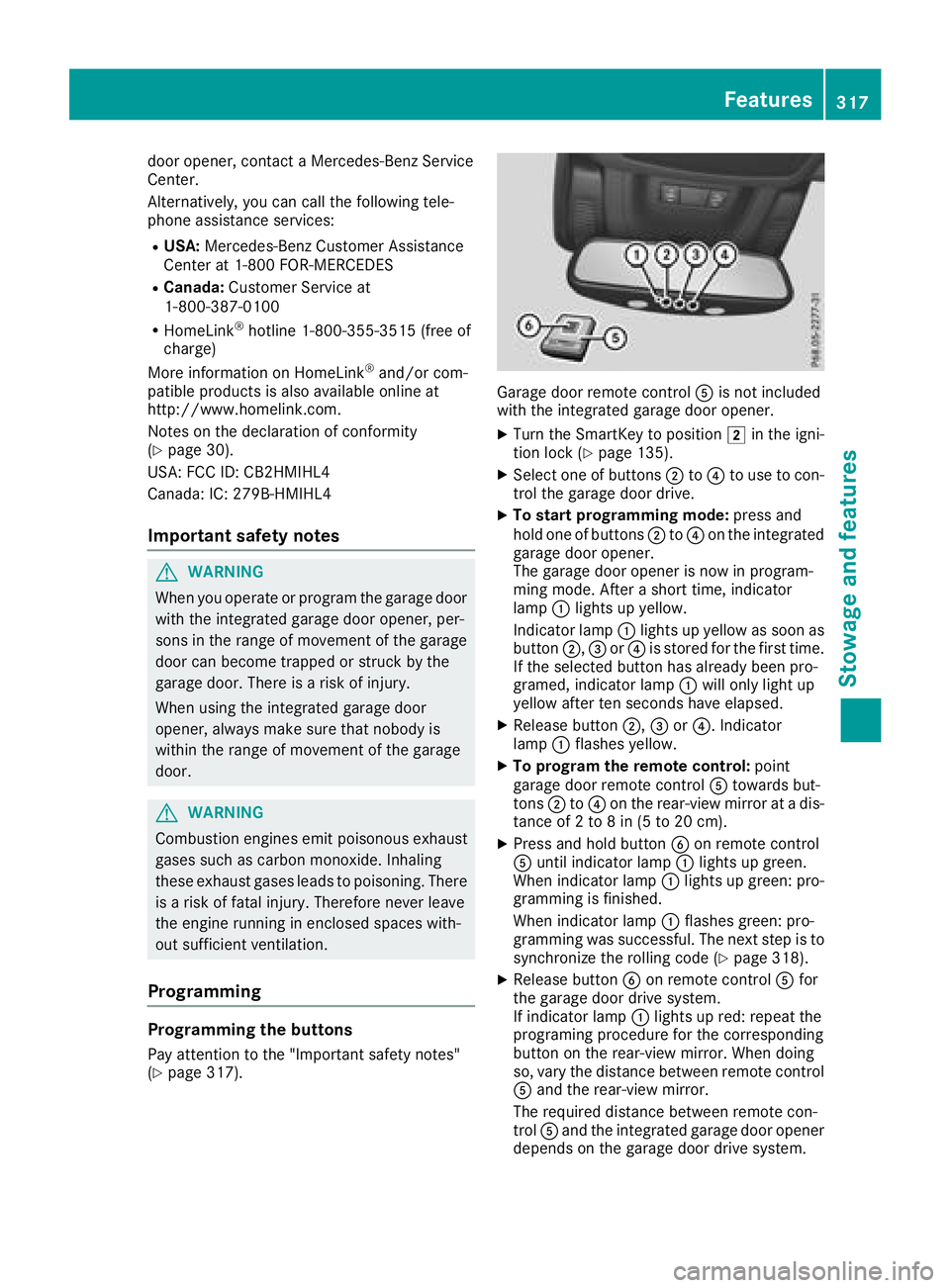
door opener, contact a Mercedes-Benz Service
Center.
Alternatively, you can call the following tele-
phone assistance services: R
USA: Mercedes-Benz Customer Assistance
Center at 1-800 FOR-MERCEDES R
Canada: Customer Service at
1-800-387-0100 R
HomeLink ®
hotline 1-800-355-3515 (free of
charge)
More information on HomeLink ®
and/or com-
patible products is also available online at
http://www.homelink.co m.
Notes on the declaration of conformity
( Y
page 30).
USA: FCC ID: CB2HMIHL4
Canada: IC: 279B-HMIHL4
Important safety notes
G WARNING
When you operate or program the garage door
with the integrated garage door opener, per-
sons in the range of movement of the garage
door can become trapped or struck by the
garage door. There is a risk of injury.
When using the integrated garage door
opener, always make sure that nobody is
within the range of movement of the garage
door.
G WARNING
Combustion engines emit poisonous exhaust
gases such as carbon monoxide. Inhaling
these exhaust gases leads to poisoning. There
is a risk of fatal injury. Therefore never leave
the engine running in enclosed spaces with-
out sufficient ventilation.
Programming
Programming the buttons
Pay attention to the "Important safety notes"
( Y
page 317). Garage door remote control
Page 362 of 398
sudden loss of pressure, bring the vehicle to a
halt by braking carefully. Avoid abrupt steering
movements.
The tire pressure monitor has a yellow warning
lamp in the instrument cluster for indicating
pressure loss or a malfunction. Whether the
warning lamp flashes or lights up indicates
whether a tire pressure is too low or the tire
pressure monitor is malfunctioning: R
if the warning lamp is lit continuously, the tire
pressure on one or more tires is significantly
too low. The tire pressure monitor is not mal-
functioning. R
if the warning lamp flashes for approximately
a minute and then remains lit constantly, the
tire pressure monitor is malfunctioning.
In addition to the warning lamp, a message
appears in the multifunction display. Observe
the information on display messages
( Y
page 268).
It may take up to ten minutes for a malfunction
of the tire pressure monitor to be indicated. A
malfunction will be indicated by the tire pres-
sure warning lamp flashing for approximately
one minute and then remaining lit. When the
malfunction has been rectified, the tire pressure
warning lamp goes out after a few minutes of
driving.
The tire pressure values indicated by the on-
board computer may differ from those meas-
ured at a gas station with a pressure gage. The
tire pressures shown by the on-board computer
refer to those measured at sea level. At high
altitudes, the tire pressure values indicated by a
pressure gage are higher than those shown by
the on-board computer. In this case, do not
reduce the tire pressures.
The operation of the tire pressure monitor can
be affected by interference from radio transmit-
ting equipment (e.g. radio headphones, two-way
radios) that may be being operated in or near the
vehicle.
Checking the tire pressure electroni-
cally X
Make sure that the SmartKey is in position H
( Y
page 135) in the ignition lock.X
Press the Y or e button on the steering
wheel to select the Serv. menu. X
Press the c or d button to select
Tire Pressure . X
Press v .
The current tire pressure of each tire is shown
in the multifunction display.
If the vehicle has been parked for longer than
20 minutes, the Tire pressure will be
displayed after driving a few minutes
message appears.
After a teach-in process, the tire pressure mon-
itor automatically detects new wheels or new
sensors. As long as a clear allocation of the tire
pressure value to the individual wheels is not
possible, the Tire Pressure Monitor Active
display message is shown instead of the tire
pressure display. The tire pressures are already
being monitored.
If an emergency spare wheel is mounted, the
system may continue to show the tire pressure
of the wheel that has been removed for a few
minutes. If this occurs, note that the value dis-
played for the position where the spare wheel is
mounted is not the same as the current tire
pressure of the emergency spare wheel.
Tire pressure monitor warning mes-
sages If the tire pressure monitor detects a pressure
loss in one or more tires, a warning message is
shown in the multifunction display. The yellow
tire pressure warning lamp then lights up. R
If the Please Correct Tire Pressure
message appears in the multifunction display,
the tire pressure in at least one tire is too low.
The tire pressure must be corrected when the
opportunity arises. R
If the Check Tires message appears in the
multifunction display, the tire pressure in at
least one tire has dropped significantly. The
tires must be checked. R
If the Warning Tire Malfunction message
appears in the multifunction display, the tire
pressure in at least one tire has dropped sud-
denly. The tires must be checked.
Be sure to observe the instructions and safety
notes in the display messages in the "Tires" sec-
tion ( Y
page 268).
If the wheel positions on the vehicle are rotated,
the tire pressures may be displayed for the
wrong positions for a short time. This is rectified
after a few minutes of driving, and the tire pres-
sures are displayed for the correct positions.360
Tire pressure
Wheels and tires
Page 383 of 398
Information regarding technical data Plug-i n hybrid: be sur e to read th e separat e
Operator's Manual. Otherwise, you may no t rec -
ognize dangers.
i The dat a state d her e specifically refers to a
vehicl e wit h standard equipment. Consult an
authorize d Mercedes-Ben z Cente r for th e
dat a for all vehicl e variants and trim levels.
Vehicle electronics
Installing two-way radios and mobile
phones (RF transmitters)
G WARNIN G
The electromagneti c radiation from two-way
radios can interfere wit h th e vehicl e electron -
ics if two-way radios are manipulated or ret -
rofitte d incorrectly. This could jeopardiz e th e
operating safet y of th e vehicle. Ther e is a ris k
of an accident.
You should hav e all wor k on electrical and
electronic component s carried out at a quali-
fie d specialist workshop.
G WARNIN G
If you incorrectl y operate two-way radios in
th e vehicle, th e electromagneti c radiation
may interfere wit h th e vehicl e electronics , for
exampl e if:R
th e two-way radi o is no t connecte d to an
exterio r antennaR
th e exterio r antenna is no t correctl y moun -
te d or is no t low-reflection
This could jeopardiz e th e operating safet y of
th e vehicle. Ther e is a ris k of an accident.
Hav e th e low-reflection exterio r antenna
installed at a qualified specialist workshop.
Always connec t two-way radios to th e low-
reflection exterio r antenna when operating in
th e vehicle.
! The operating permit may be invalidated if
th e instruction s for installation and use of
two-way radios are no t observed. In particular, th e followin g condition s must be
complied with: R
only approve d wavebands may be used R
observ e th e maximum permissible output
in these wavebands R
only approve d antenna position s may be
used
Excessiv e levels of electromagneti c radiation
may caus e damag e to your healt h and th e healt h
of others. Using an exterio r antenna takes int o
accoun t curren t scientific discussion s relating
to th e possible healt h hazards that may result
from electromagneti c fields.
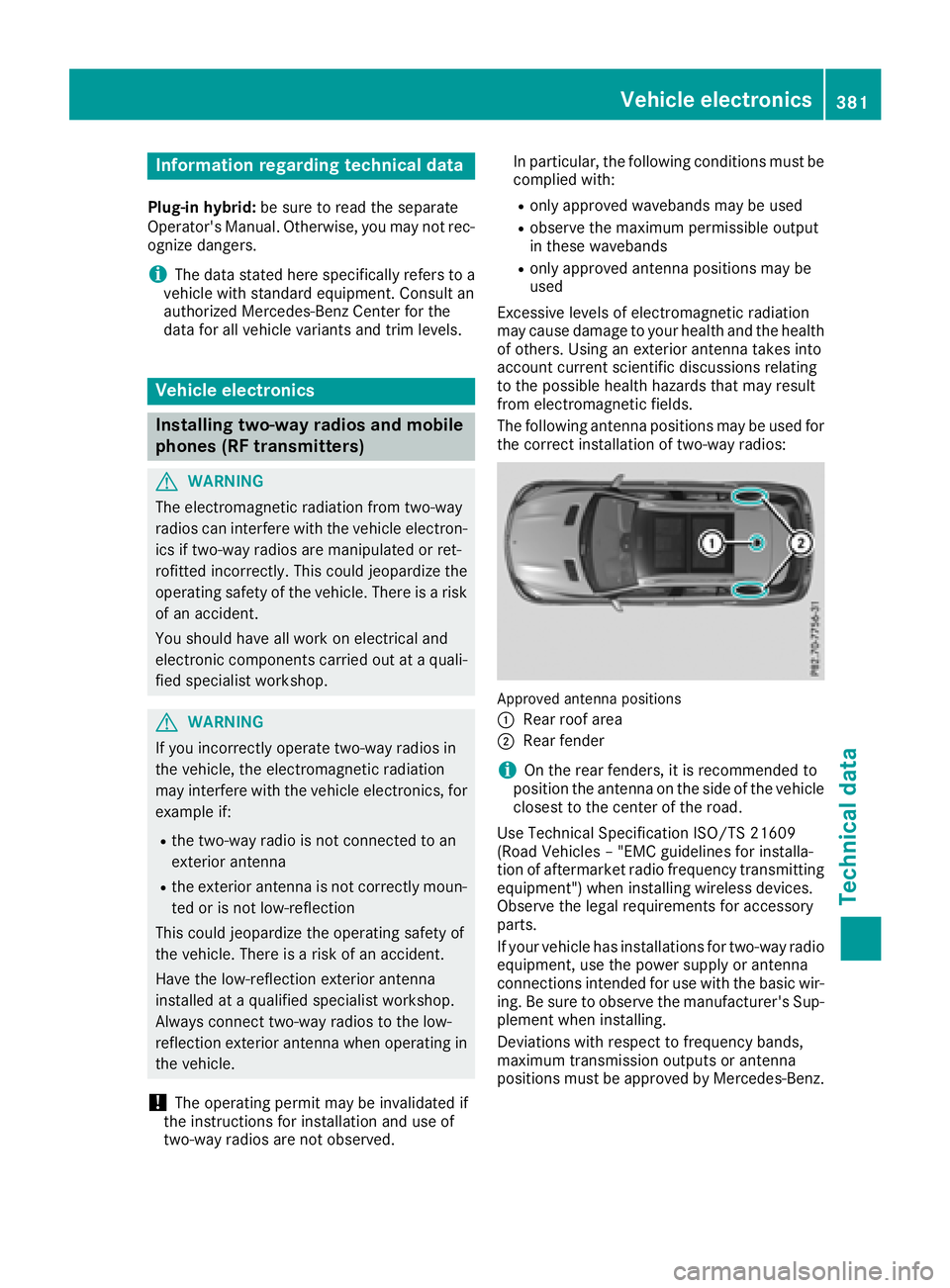
The fo llowin g a
ntenna position s may be used for
th e correc t installation of two-way radios:
Approved antenna position s
C
Rear roo f areaD
Rear fender
i On th e rear fenders, it is recommended to
position th e antenna on th e side of th e vehicl e
closes t to th e center of th e road .
Use Technical Specification ISO/TS 2160 9
(Road Vehicles – "EM C guidelines for installa-
tion of aftermarket radi o frequency transmitting
equipment") when installin g wireless devices.
Observ e th e legal requirements for accessory
parts.
If your vehicl e has installation s for two-way radi o
equipment, use th e power suppl y or antenna
connection s intended for use wit h th e basic wir-
ing . Be sur e to observ e th e manufacturer' s Sup -
plemen t when installing.
Deviation s wit h respec t to frequency bands,
maximum transmission output s or antenna
position s must be approve d by Mercedes-Benz.Vehicle electronics 381
Technical data Z
Page 384 of 398
The maximum transmission output (PEAK) at the
base of the antenna must not exceed the fol-
lowing values:
Frequency band Maximum
transmission
output
Short wave
3 - 54 MHz 100 W
4 m waveband
74 - 88 MHz 30 W
2 m waveband
144 - 174 MHz 50 W
Trunked radio system/
Tetra
380 - 460 MHz 10 W
70 cm waveband
400 - 460 MHz 35 W
Mobile communications
(2G/3G/4G) 10 W
The following can be used in the vehicle without
restrictions: R
Two-way radios with a maximum transmission
output of up to 100 mW R
Two-way radios with transmitter frequencies
in the 380 - 410 MHz waveband and a maxi-
mum transmission output of up to 2 W
(trunked radio/Tetra) R
Mobile phones (2G/3G/4G)
There are no restrictions when positioning the
antenna on the outside of the vehicle for the
following wavebands: R
Trunked radio system/Tetra R
70 cm waveband R
2G/3G/4G Identification plates
Vehicle identification plate with vehi-
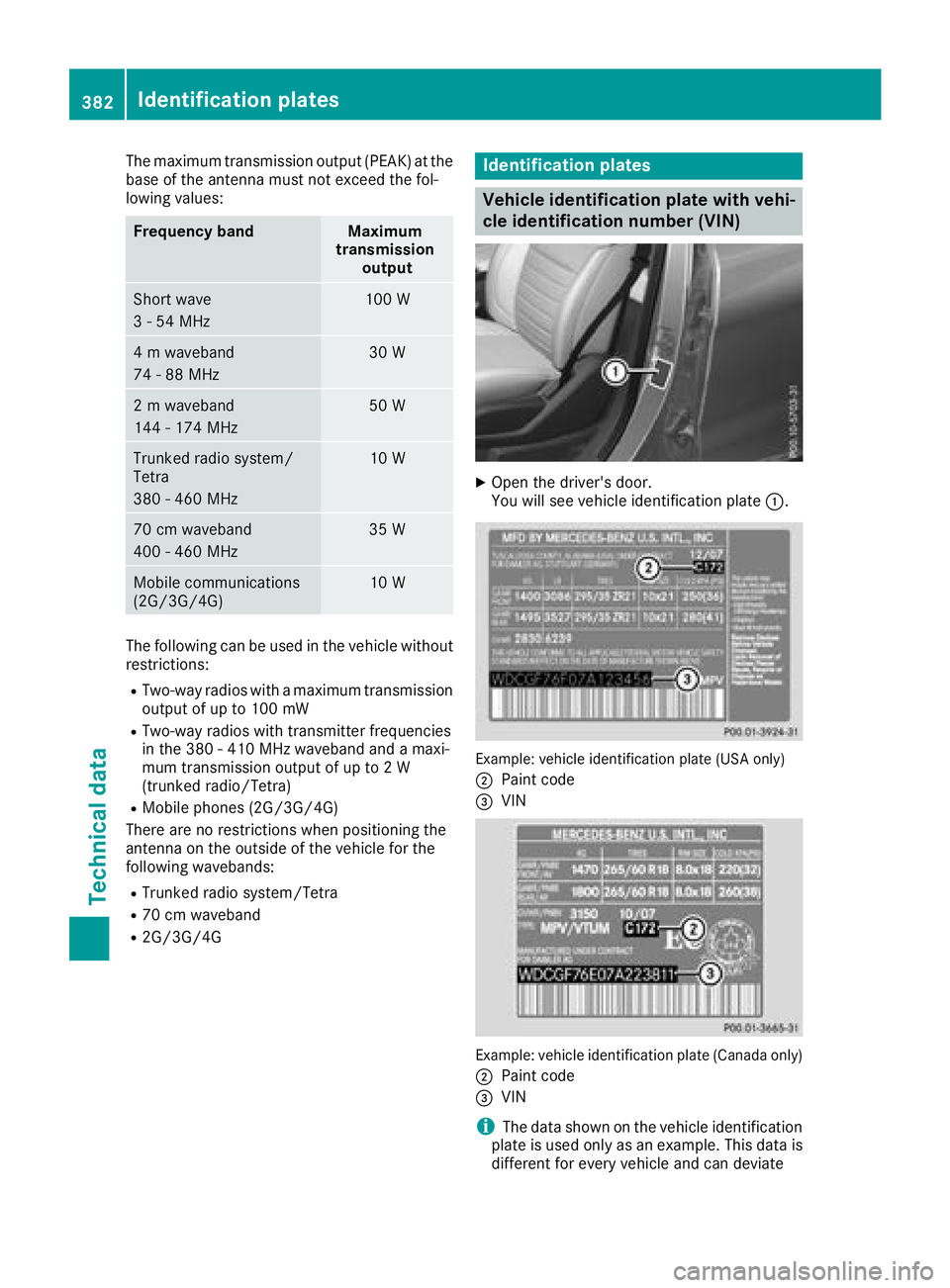
cle identification number (VIN) X
Open the driver's door.
You will see vehicle identification plate C .
Example: vehicle identification plate (USA only)
D
Paint code