load capacity MERCEDES-BENZ GLE 2018 Owners Manual
[x] Cancel search | Manufacturer: MERCEDES-BENZ, Model Year: 2018, Model line: GLE, Model: MERCEDES-BENZ GLE 2018Pages: 398, PDF Size: 9.25 MB
Page 24 of 398

Distribution of the vehicle occu-
pants (definition) ............................ 371
DOT (Department of Transporta-
tion) (definition) ............................. 369
DOT, Tire Identification Number
(TIN) ............................................... 368
GAWR (Gross Axle Weight Rating)
(definition) .................................... .3 69
GTW (Gross Trailer Weight) (defi-
nition) ............................................ 370
GVW (Gross Vehicle Weight) (def-
inition) .......................................... .3 70
GVWR (Gross Vehicle Weight Rat-
ing) (definition) .............................. 370
Important safety notes .................. 351
Increased vehicle weight due to
optional equipment (definition) ...... 369
Information on driving .................... 351
Kilopascal (kPa) (definition) ........... 370
Labeling (overview) ........................ 366
Load bearing index (definition) ...... 371
Load index ..................................... 368
Load index (definition) ................... 370
M+S tires ....................................... 353
Maximum load on a tire (defini-
tion) ............................................... 370
Maximum loaded vehicle weight
(definition) ..................................... 370
Maximum permissible tire pres-
sure (definition) ............................. 370
Maximum tire load ......................... 368
Maximum tire load (definition) ....... 370
MOExtended tires .......................... 353
Optional equipment weight (defi-
nition) ............................................ 371
PSI (pounds per square inch) (def-
inition) ........................................... 370
Replacing ....................................... 371
Service life ..................................... 352
Sidewall (definition) ....................... 371
Snow chains .................................. 353
Speed rating (definition) ................ 370
Storing ........................................... 372
Structure and characteristics
(definition) ..................................... 369
Summer tires in winter .................. 353
Temp erature .................................. 365 T
IN (Tire Identification Number)
(definition) ..................................... 371
Tire bead (definition) ...................... 370
Tire pressure (definition) ................ 370
Tire pressures (recommended) ...... 369
Tire size (data) ............................... 376
Tire size designation, load-bearing
capacity, speed rating .................... 366
Tire tread ....................................... 352
Tire tread (definition) ..................... 370
Total load limit (definition) ............. 371
Traction ......................................... 365
Traction (definition) ....................... 371
Tread wear ..................................... 365
TWR (permissible trailer drawbar
noseweight) (definition) ................. 371
Uniform Tire Quality Grading
Standards ...................................... 364
Uniform Tire Quality Grading
Standards (definition) .................... 369
Wear indicator (definition) ............. 371
Wheel and tire combination ........... 376
Wheel rim (definition) .................... 369
see Flat tire
Top Tether ............................................ 62
Tow-starting
Emergency engine starting ............ 348
Important safety notes .................. 345
Towing a trailer
Axle load, permissible .................... 394
Cleaning the trailer tow hitch ......... 331
Coupling up a trailer ...................... 222
Decoupling a trailer ....................... 224
Driving tips .................................... 220
Important safety notes .................. 219
Installing the ball coupling ............. 221
Lights display message .................. 255
Mounting dimensions .................... 394
Parking Assist PARKTRONIC .......... 187
Power supply ................................. 225
Pulling away with a trailer .............. 138
Removing the ball coupling ............ 224
Trailer loads ................................... 394
Towing away
Important safety guidelines ........... 345
Insta l ling the towing eye ................ 346
Notes for 4MATIC vehicles ............ 348
Removing the towing eye ............... 34622
Index
Page 365 of 398

able cargo and luggage load capacity is
650 lbs (1400 - 750 (5 x 150) = 650 lbs). X
Step 5: Determine the combined weight of
luggage and cargo being loaded on the vehi- cle. That weight may not safely exceed the
available cargo and luggage load capacity cal-
culated in step 4.
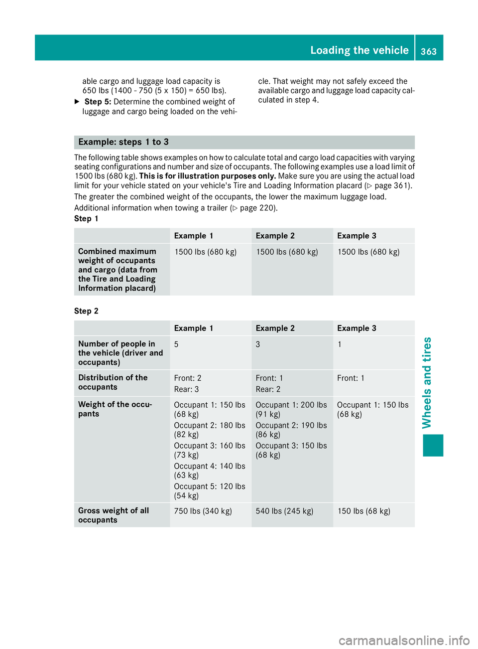
Example: steps 1 to 3 The following table shows examples on how to calculate total and cargo load capacities with varying
seating configurations and number and size of occupants. The following examples use a load limit of
1500 lbs (680 kg). This is for illustration purposes only. Make sure you are using the actual load
limit for your vehicle stated on your vehicle's Tire and Loading Information placard ( Y
page 361).
The greater the combined weight of the occupants, the lower the maximum luggage load.
Additional information when towing a trailer ( Y
page 220).
Step 1
Example 1 Example 2 Example 3
Combined maximum
weight of occupants
and cargo (data from
the Tire and Loading
Information placard) 1500 lbs (680 kg) 1500 lbs (680 kg) 1500 lbs (680 kg)
Step 2
Example 1 Example 2 Example 3
Number of people in
the vehicle (driver and
occupants) 5 3 1
Distribution of the
occupants Front: 2
Rear: 3 Front: 1
Rear: 2 Front: 1
Weight of the occu-
pants Occupant 1: 150 lbs
(68 kg)
Occupant 2: 180 lbs
(82 kg)
Occupant 3: 160 lbs
(73 kg)
Occupant 4: 140 lbs
(63 kg)
Occupant 5: 120 lbs
(54 kg) Occupant 1: 200 lbs
(91 kg)
Occupant 2: 190 lbs
(86 kg)
Occupant 3: 150 lbs
(68 kg) Occupant 1: 150 lbs
(68 kg)
Gross weight of all
occupants 750 lbs (340 kg) 540 lbs (245 kg) 150 lbs (68 kg)Loading the vehicle 363
Wheels and tires Z
Page 372 of 398

Speed rating The speed rating is part of the tire identification.
It specifies the speed range for which the tire is
approved.
GTW (Gross Trailer Weight) The GTW is the weight of a trailer including the
weight of the load, luggage, accessories etc. on
the trailer.
GVW (Gross Vehicle Weight) The gross vehicle weight includes the weight of
the vehicle including fuel, tools, the spare wheel,
accessories installed, occupants, luggage and
the drawbar noseweight, if applicable. The gross
vehicle weight must not exceed the gross vehi-
cle weight rating GVWR as specified on the vehi-
cle identification plate on the B-pillar on the
driver's side.
GVWR (Gross Vehicle Weight Rating) The GVWR is the maximum permissible gross
weight of a fully loaded vehicle (the weight of the
vehicle including all accessories, occupants,
fuel, luggage and the drawbar noseweight, if
applicable). The gross vehicle weight rating is
specified on the vehicle identification plate on
the B-pillar on the driver's side.
Maximum loaded vehicle weight The maximum weight is the sum of: R
the curb weight of the vehicle R
the weight of the accessories R
the load limit R
the weight of the factory installed optional
equipment
Kilopascal (kPa)
Metric unit for tire pressure. 6.9 kPa corre-
sponds to 1 psi. Another unit for tire pressure is
bar. 100 kilopascals (kPa) are the equivalent of
1 bar.
Load index
In addition to the load-bearing index, the load
index may also be imprinted on the sidewall of
the tire. This specifies the load-bearing capacity
more precisely.
Curb weight
The weight of a vehicle with standard equipment
including the maximum capacity of fuel, oil and
coolant. It also includes the air-conditioning sys- tem and optional equipment if these are instal-
led in the vehicle, but does not include passen-
gers or luggage.
Maximum load rating The maximum tire load is the maximum permis-
sible weight in kilograms or lbs for which a tire is
approved.
Maximum permissible tire pressure Maximum permissible tire pressure for one tire.
Maximum load on one tire Maximum load on one tire. This is calculated by
dividing the maximum axle load of one axle by
two.
PSI (pounds per square inch) A standard unit of measure for tire pressure.
Aspect ratio Relationship between tire height and tire width
in percent.
Tire pressure This is pressure inside the tire applying an out-
ward force to each square inch of the tire's sur-
face. The tire pressure is specified in pounds per
square inch (psi), in kilopascal (kPa) or in bar.
The tire pressure should only be corrected when
the tires are cold.
Cold tire pressure The tires are cold: R
if the vehicle has been parked with the tires
out of direct sunlight for at least three hours
and R
if the vehicle has not been driven further than
1 mile (1.6 km)
Tread
The part of the tire that comes into contact with
the road.
Bead
The tire bead ensures that the tire sits securely
on the wheel. There are several steel wires in the
bead to prevent the tire from coming loose from
the wheel rim.370
All about wheels and tires
Wheels and tires
Page 375 of 398

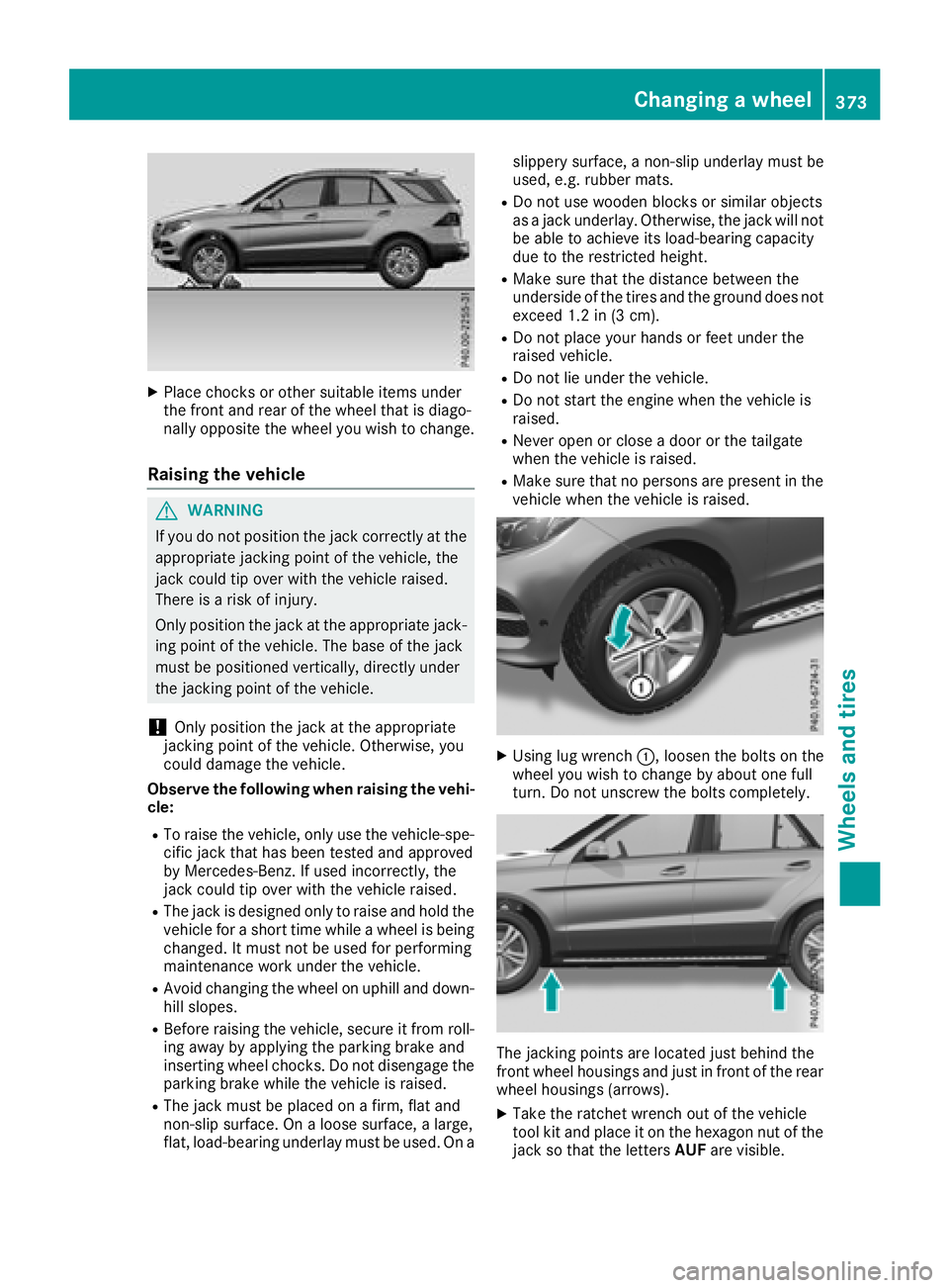
X
Place chocks or other suitable items under
the front and rear of the wheel that is diago-
nally opposite the wheel you wish to change.
Raising the vehicle
G WARNING
If you do not position the jack correctly at the
appropriate jacking point of the vehicle, the
jack could tip over with the vehicle raised.
There is a risk of injury.
Only position the jack at the appropriate jack-
ing point of the vehicle. The base of the jack
must be positioned vertically, directly under
the jacking point of the vehicle.
! Only position the jack at the appropriate
jacking point of the vehicle. Otherwise, you
could damage the vehicle.
Observe the following when raising the vehi-
cle: R
To raise the vehicle, only use the vehicle-spe-
cific jack that has been tested and approved
by Mercedes-Benz. If used incorrectly, the
jack could tip over with the vehicle raised. R
The jack is designed only to raise and hold the
vehicle for a short time while a wheel is being
changed. It must not be used for performing
maintenance work under the vehicle. R
Avoid changing the wheel on uphill and down-
hill slopes. R
Before raising the vehicle, secure it from roll-
ing away by applying the parking brake and
inserting wheel chocks. Do not disengage the
parking brake while the vehicle is raised. R
The jack must be placed on a firm, flat and
non-slip surface. On a loose surface, a large,
flat, load-bearing underlay must be used. On a slippery surface, a non-slip underlay must be
used, e.g. rubber mats. R
Do not use wooden blocks or similar objects
as a jack underlay. Otherwise, the jack will not
be able to achieve its load-bearing capacity
due to the restricted height. R
Make sure that the distance between the
underside of the tires and the ground does not
exceed 1.2 in (3 cm). R
Do not place your hands or feet under the
raised vehicle. R
Do not lie under the vehicle. R
Do not start the engine when the vehicle is
raised. R
Never open or close a door or the tailgate
when the vehicle is raised. R
Make sure that no persons are present in the
vehicle when the vehicle is raised.
X
Using lug wrench �C , loosen the bolts on the
wheel you wish to change by about one full
turn. Do not unscrew the bolts completely.
The jacking points are located just behind the
front wheel housings and just in front of the rear
wheel housings (arrows). X
Take the ratchet wrench out of the vehicle
tool kit and place it on the hexagon nut of the
jack so that the letters AUF are visible.Changing a wheel 373
Wheels and tires Z