tire size MERCEDES-BENZ GLE COUPE 2019 Owner's Manual
[x] Cancel search | Manufacturer: MERCEDES-BENZ, Model Year: 2019, Model line: GLE COUPE, Model: MERCEDES-BENZ GLE COUPE 2019Pages: 370, PDF Size: 11.22 MB
Page 23 of 370
Direction of rotatio
n...................... 348
Display message ............................ 245
Distribution of the vehicle occu-
pants (definition) ............................ 347
DOT (Department of Transporta-
tion) (definition) ............................. 345
DOT, Tire Identification Number
(TIN) ............................................... 345
GAWR (Gross Axle Weight Rating)
(definition) ..................................... 346
GTW (Gross Trailer Weight) (defi-
nition) ............................................ 346
GVW (Gross Vehicle Weight) (def-
inition) ........................................... 346
GVWR (Gross Vehicle Weight Rat-
ing) (definition) .............................. 346
Important safety notes .................. 327
Increased vehicle weight due to
optional equipment (definition) ...... 346
Information on driving .................... 327
Kilopascal (kPa) (definition) ........... 346
Labeling (overview) ........................ 342
Load bearing index (definition) ...... 347
Load index ..................................... 344
Load index (definition) ................... 346
M+S tire s....................................... 329
Maximum load on a tire (defini-
tion) ............................................... 346
Maximum loaded vehicle weight
(definition) ..................................... 346
Maximum permissible tire pres-
sure (definition) ............................. 346
Maximum tire load ......................... 344
Maximum tire load (definition) ....... 346
MOExtended tire s.......................... 328
Optional equipment weight (defi-
nition) ............................................ 347
PSI (pounds per square inch) (def-
inition) ........................................... 347
Replacing ....................................... 347
Service life ..................................... 328
Sidewall (definition) ....................... 347
Snow chains .................................. 329
Speed rating (definition) ................ 346
Storing ........................................... 348
Structure and characteristics
(definition) ..................................... 345
Summer tires in winter .................. 329 Temperature .................................. 341
TIN (Tire Identification Number)
(definition) ..................................... 347
Tire bead (definition) ...................... 347
Tire pressure (definition) ................ 347
Tire pressures (recommended) ...... 346
Tire size (data) ............................... 352
Tire size designation, load-bearing
capacity, speed rating .................... 342
Tire tread ....................................... 328
Tire tread (definition) ..................... 347
Total load limit (definition) ............. 347
Traction ......................................... 341
Traction (definition) ....................... 347
Tread wear ..................................... 341
TWR (permissible trailer drawbar
noseweight) (definition) ................. 347
Uniform Tire Quality Grading
Standards ...................................... 341
Uniform Tire Quality Grading
Standards (definition) .................... 345
Wear indicator (definition) ............. 347
Wheel and tire combination ........... 352
Wheel rim (definition) .................... 346
see Flat tire
Top Tether ............................................ 60
Tow-starting
Emergency engine starting ............ 324
Important safety notes .................. 321
Towing
Permitted towing methods ............ 322
Towing a trailer
Axle load, permissibl e.................... 367
Cleaning the trailer tow hitch ......... 306
Coupling up a traile r...................... 202
Decoupling a trailer ....................... 204
Driving tip s.................................... 200
Important safety notes .................. 199
Installing the ball coupling ............. 201
Lights display message .................. 235
Mounting dimensions .................... 367
Parking Assist PARKTRONIC .......... 173
Power supply ................................. 205
Pulling away with a traile r.............. 130
Removing the ball coupling ............ 205
Trailer load s................................... 367
Towing away
Important safety guidelines ........... 321 Index
21
Page 25 of 370
Transporting ..................................3
23
Unlocking (in an emergency) ........... 81
Unlocking (SmartKey) ..................... .74
Vehicle data ................................... 364
Vehicle data
Roof load (maximum) .....................3 64
Trunk load (maximum) ................... 364
Vehicle data (off-road driving)
Approach/departure angle ............ 366
Maximum gradient climbing abil-
ity ................................................. .367
Maximum water depth ................... 366
Vehicle dimensions ........................... 364
Vehicle emergency locking ................ 81
Vehicle identification number
see VIN
Vehicle identification plate .............. 358
Vehicle level
AIRMATIC ...................................... 170
Vehicle level (display message) ....... 239
Vehicle tool kit .................................. 310
Video
Operating the DVD ......................... 214
see also Digital Operator's Man-
ual ................................................. .264
VIN ...................................................... 358
Seat ............................................... 359
Type plate ...................................... 358 W
Warning and indicator lamps ABS ................................................ 254
Brakes .......................................... .253
Coolant .......................................... 260
Distance warning ........................... 262
Engine diagnostics ......................... 259
ESP ®
.............................................. 256
ESP ®
OFF ....................................... 257
Fuel tank ........................................ 259
Overview .......................................... 36
Parking brake ................................ 259
PASSENGER AIR BAG ..................... .43
Reserve fuel .................................. .259
Restraint system ............................ 259
Seat belt ........................................ 251
Tire pressure monitor .................... 263
Warranty .............................................. 27 Washer fluid
Display message ............................ 249
Weather display (COMAND)
see also Digital Operator's Man-
ual.................................................. 264
Wheel and tire combinations
Tires ............................................... 352
Wheel bolt tightening torque ........... 351
Wheel chock ...................................... 349
Wheels
Changing a whee l.......................... 347
Checking ........................................ 327
Cleaning ......................................... 304
Emergency spare wheel ................. 353
Important safety notes .................. 327
Information on driving .................... 327
Interchanging/changing ................ 347
Mounting a new whee l................... 351
Mounting a whee l.......................... 348
Overview ........................................ 327
Removing a whee l.......................... 350
Snow chains .................................. 329
Storing ........................................... 348
Tightening torque ........................... 351
Wheel size/tire size ....................... 352
Window curtain air bag
Display message ............................ 232
Operation ......................................... 49
Windows
see Side windows
Windshield
Defrosting ...................................... 122
Windshield washer fluid
see Windshield washer system
Windshield washer system
Adding washer fluid ....................... 299
Important safety notes .................. 363
Windshield wipers
Problem (malfunction) ................... 114
Replacing the wiper blades ............ 111
Replacing the wiper blades
(MAGIC VISION CONTROL) ............ 113
Switching on/of f........................... 111
Winter driving
Slippery road surfaces ................... 151
Winter operation
Overview ........................................ 329
Radiator cover ............................... 297 Index
23
Page 70 of 370
Important safety notes
G
WARNING
If ESP ®
is malfunctioning, ESP ®
is unable to
stabilize the vehicle. Additionally, further driv- ing safety systems are deactivated. This
increases the risk of skidding and an accident.
Drive on carefully. Have ESP ®
checked at a
qualified specialist workshop.
! Only operate the vehicle for a maximum of
ten seconds on a brake test dynamometer.
Switch off the ignition.
Application of the brakes by ESP ®
may oth-
erwise destroy the brake system.
! A function or performance test should only
be carried out on a two-axle dynamometer.
Before you operate the vehicle on such a
dynamometer, please consult a qualified
workshop. You could otherwise damage the
drive train or the brake system.
! Do not tow vehicles with 4MATIC with the
front or rear axle raised.
ESP ®
is only deactivated if the 00BBwarning
lamp is lit continuously.
If the 00E5 warning lamp and the 00BBwarning
lamp are lit continuously, ESP ®
is not available
due to a malfunction.
Observe the information on warning lamps
(Y page 256) and display messages which may
be shown in the instrument cluster
(Y page 224).
i Only use wheels with the recommended tire
sizes. Only then will ESP ®
function properly.
Characteristics of ESP ®General information
If the 00E5 ESP warning lamp goes out before
beginning the journey, ESP ®
is automatically
active.
If ESP ®
intervenes, the 00E5ESP®
warning lamp
flashes in the instrument cluster. If ESP
®
intervenes:
X Do not deactivate ESP ®
under any circum-
stances.
X Only depress the accelerator pedal as far as
necessary when pulling away.
X Adapt your driving style to suit the prevailing
road and weather conditions.
ECO start/stop function
The ECO start/stop function switches the
engine off automatically when the vehicle stops moving. The engine starts automatically when
the driver wants to pull away again. ESP ®
remains in its previously selected status, e.g. if
ESP ®
was deactivated before the engine was
automatically switched off.
Deactivating/activating ESP ® Important safety notes
i Observe the "Important safety notes" sec-
tion (Y page 64).
You can select between the following states of
ESP ®
:
R ESP ®
is activated.
R ESP ®
is deactivated. G
WARNING
If you deactivate ESP ®
, ESP ®
no longer sta-
bilizes the vehicle. There is an increased risk
of skidding and an accident.
Only deactivate ESP ®
in the situations descri-
bed in the following.
It may be best to deactivate ESP ®
in the follow-
ing situations:
R when using snow chains
R in deep snow
R on sand or gravel
Spinning the wheels results in a cutting action
which provides better grip.
i Activate ESP ®
as soon as the situations
described above no longer apply. ESP ®
will
otherwise not be able to stabilize the vehicle if
the vehicle starts to skid or a wheel starts to
spin. 68
Driving safety systemsSafety
Page 313 of 370
X
Secure the vehicle against rolling away
(Y page 144).
X If possible, bring the front wheels into the
straight-ahead position.
X Vehicles with the AIRMATIC package:
make sure that the normal vehicle level is
selected (Y page 170).
X Switch off the engine.
X Vehicles without KEYLESS-GO: remove the
SmartKey from the ignition lock.
X Vehicles with KEYLESS-GO: open the driv-
er's door.
The vehicle electronics are now in position
0092. This means no SmartKey is in the ignition
lock.
X Vehicles with KEYLESS-GO: remove the
Start/Stop button from the ignition lock
(Y page 127).
X Make sure that the engine cannot be started
via your smartphone (Y page 129).
X Make sure that the passengers are not endan-
gered as they do so. Make sure that no one is
near the danger area while a wheel is being
changed. Anyone who is not directly assisting
in the wheel change should, for example,
stand behind the barrier.
X Get out of the vehicle. Pay attention to traffic
conditions when doing so.
X Close the driver's door.
X Unload heavy luggage.
i Only operate the tire inflation compressor
using a 12 V socket, even if the ignition is
turned off (Y page 283).
An emergency cut-out ensures that the on-
board voltage does not drop too low. If the on-
board voltage is too low, the power to the
sockets is automatically cut. This ensures
that there is sufficient power to start the
engine. MOExtended tires (tires with run-flat
properties)
General notes With MOExtended tires (tires with run flat char-
acteristics), you can continue to drive your vehi-cle even if there is a total loss of pressure in one
or more tires. The affected tire must not show
any clearly visible damage. You can recognize an MOExtended tire by the
MOExtended marking which appears on the
sidewall of the tire. You will find this marking
next to the tire size designation, the load-bear-
ing capacity and the speed index (Y
page 342).
MOExtended tires may only be used in conjunc-
tion with an active tire pressure loss warning
system or with an active tire pressure monitor.
If a pressure loss warning message appears in the multifunction display:
R observe the instructions in the display mes-
sages (Y page 245).
R check the tire for damage
R if driving on, observe the following notes
The driving distance possible in run-flat mode is approximately 50 miles (80 km) when the vehi-
cle is partially laden and approximately 18 miles
(30 km) when the vehicle is fully laden.
In addition to the vehicle load, the driving dis-
tance possible depends upon:
R Vehicle speed
R Road condition
R Outside temperature
The driving distance possible in run-flat mode
may be reduced by extreme driving conditions
or maneuvers, or it can be increased through a
moderate style of driving.
The driving distance possible in run-flat mode is
counted from the moment the tire pressure loss warning appears in the multifunction display.
You must not exceed a maximum permissible
speed of 50 mph (80 km/h).
When replacing one or all tires, please observe
the following specifications for your vehicle's
tires:
R Size
R Type and
R The "MOExtended" mark
i Vehicles equipped with MOExtended tires
are not equipped with a TIREFIT kit at the fac- tory. It is therefore recommended that you
additionally equip your vehicle with a TIREFIT
kit if you mount tires that do not feature run- flat characteristics, e.g. winter tires. A TIREFIT
kit may be obtained from a qualified specialist workshop. Flat tire
311Breakdown assistance
Page 330 of 370
R
tears in the tires
R bulges on tires
R deformation or severe corrosion on wheels
Regularly check the tire tread depth and the
condition of the tread across the whole width of
all tires (Y page 328). If necessary, turn the
front wheels to full lock in order to inspect the
inner side of the tire surface.
All wheels must have a valve cap to protect the
valve against dirt and moisture. Do not mount
anything onto the valve other than the standard valve cap or other valve caps approved by
Mercedes-Benz for your vehicle. Do not use anyother valve caps or systems, e.g. tire pressure
monitoring systems.
Regularly check the pressure of all the tires par- ticularly prior to long trips. Adjust the tire pres-
sure as necessary (Y page 330).
Observe the notes on the emergency spare
wheel (Y page 353).
The service life of tires depends, among other
things, on the following factors:
R Driving style
R Tire pressure
R Distance covered Notes on tire tread
G
WARNING
If there is insufficient tire tread, the tire trac-
tion decreases. The tire tread is no longer able to dissipate water. This increases the risk of
hydroplaning when the road surface is wet,
particularly when the vehicle's speed is not
adapted to the road conditions. There is a risk
of an accident.
When the tire pressure is too high or too low,
tires may wear differently at different points
on the tire tread. Therefore, regularly check
the tire tread depth and the condition of the
tread across the whole width of all tires.
Minimum tire tread depth on:
R Summer tires: 00CEin (3 mm)
R M+S tires: 00CFin (4 mm)
For safety reasons, have the tires replaced
before they reach the legally prescribed min-
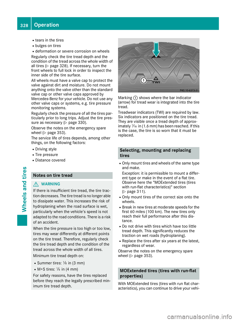
imum tire tread depth. Marking
0043shows where the bar indicator
(arrow) for tread wear is integrated into the tire
tread.
Treadwear indicators (TWI) are required by law. Six indicators are positioned on the tire tread.
They are visible once a tread depth of approx-
imately 00CDin (1.6 mm) has been reached. If this
is the case, the tire is so worn that it must be
replaced. Selecting, mounting and replacing
tires
R Only mount tires and wheels of the same type
and make.
Exception: it is permissible to mount a differ-
ent type or make in the event of a flat tire.
Observe here the "MOExtended tires (tires
with run-flat characteristics)" section
(Y page 311).
R Only mount tires of the correct size onto the
wheels.
R Break in new tires at moderate speeds for the
first 60 miles (100 km). The new tires only
reach their full performance after this dis-
tance.
R Do not drive with tires which have too little
tread depth. This significantly reduces the
traction on wet roads (hydroplaning).
R Replace the tires after six years at the latest,
regardless of wear.
Observe the notes on the emergency spare
wheel (Y page 353). MOExtended tires (tires with run-flat
properties)
With MOExtended tires (tires with run flat char- acteristics), you can continue to drive your vehi- 328
OperationWheels and tires
Page 333 of 370
R
incorrectly set tire pressure
R sudden loss of tire pressure, e.g. from a for-
eign object that has penetrated the tire
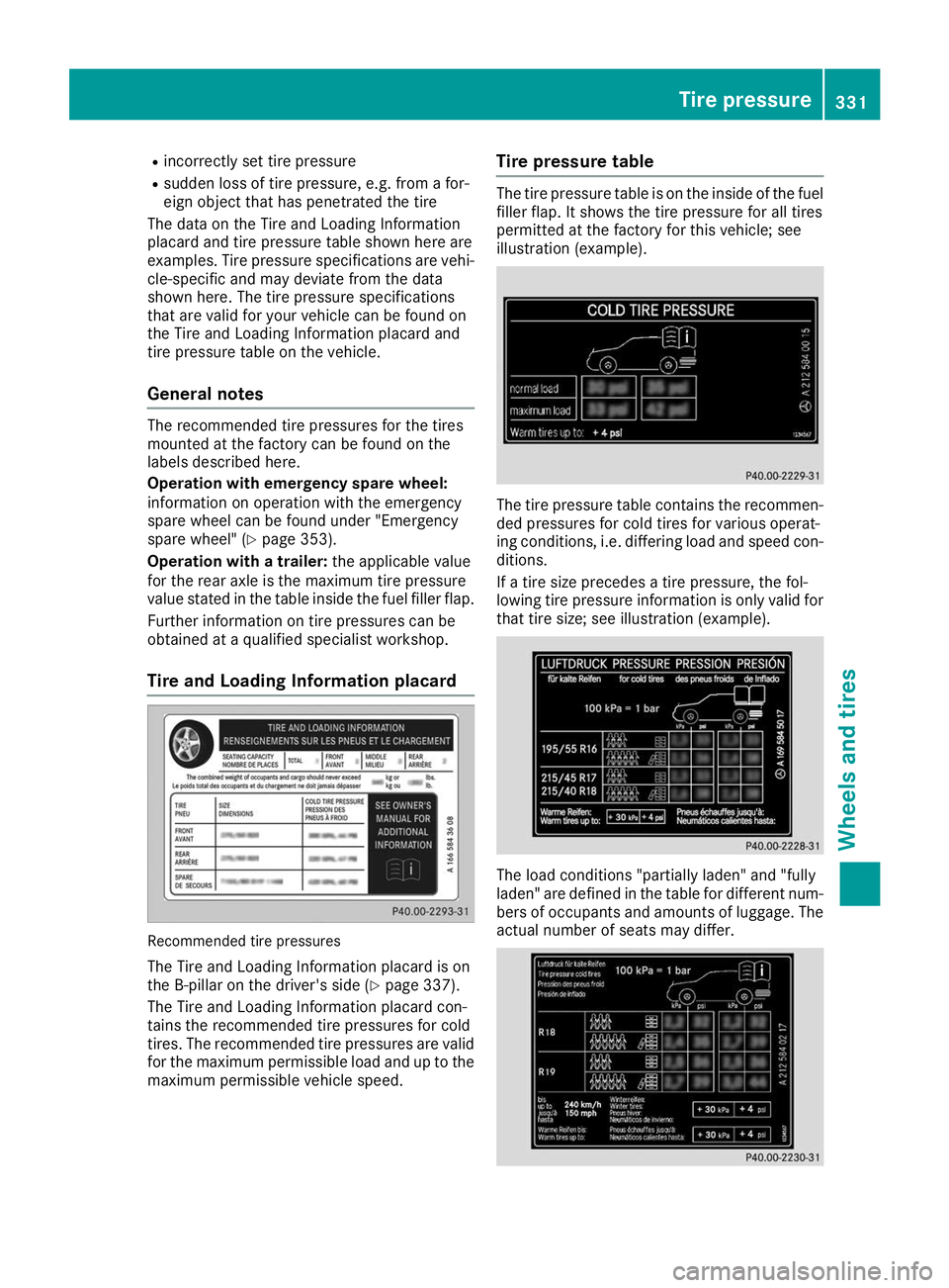
The data on the Tire and Loading Information
placard and tire pressure table shown here are
examples. Tire pressure specifications are vehi- cle-specific and may deviate from the data
shown here. The tire pressure specifications
that are valid for your vehicle can be found on
the Tire and Loading Information placard and
tire pressure table on the vehicle.
General notes The recommended tire pressures for the tires
mounted at the factory can be found on the
labels described here.
Operation with emergency spare wheel:
information on operation with the emergency
spare wheel can be found under "Emergency
spare wheel" (Y page 353).
Operation with a trailer: the applicable value
for the rear axle is the maximum tire pressure
value stated in the table inside the fuel filler flap.
Further information on tire pressures can be
obtained at a qualified specialist workshop.
Tire and Loading Information placard Recommended tire pressures
The Tire and Loading Information placard is on
the B-pillar on the driver's side (Y page 337).
The Tire and Loading Information placard con-
tains the recommended tire pressures for cold
tires. The recommended tire pressures are valid for the maximum permissible load and up to the
maximum permissible vehicle speed. Tire pressure table The tire pressure table is on the inside of the fuel
filler flap. It shows the tire pressure for all tires
permitted at the factory for this vehicle; see
illustration (example). The tire pressure table contains the recommen-
ded pressures for cold tires for various operat-
ing conditions, i.e. differing load and speed con-
ditions.
If a tire size precedes a tire pressure, the fol-
lowing tire pressure information is only valid for that tire size; see illustration (example). The load conditions "partially laden" and "fully
laden" are defined in the table for different num- bers of occupants and amounts of luggage. The
actual number of seats may differ. Tire pressure
331Wheels and tires Z
Page 334 of 370
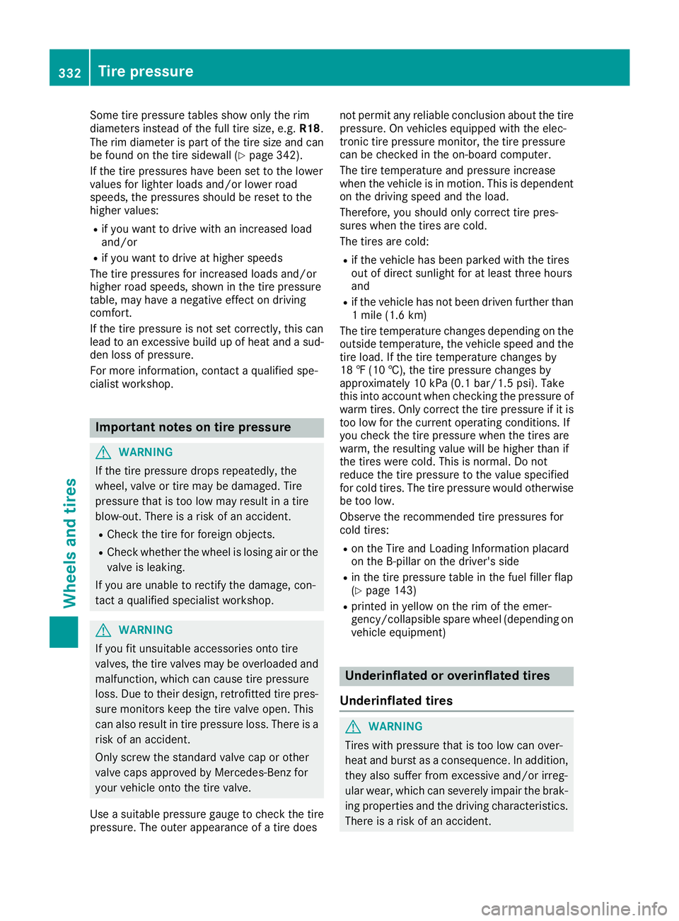
Some tire pressure tables show only the rim
diameters instead of the full tire size, e.g. R18.
The rim diameter is part of the tire size and can
be found on the tire sidewall (Y page 342).
If the tire pressures have been set to the lower
values for lighter loads and/or lower road
speeds, the pressures should be reset to the
higher values:
R if you want to drive with an increased load
and/or
R if you want to drive at higher speeds
The tire pressures for increased loads and/or
higher road speeds, shown in the tire pressure
table, may have a negative effect on driving
comfort.
If the tire pressure is not set correctly, this can
lead to an excessive build up of heat and a sud- den loss of pressure.
For more information, contact a qualified spe-
cialist workshop. Important notes on tire pressure
G
WARNING
If the tire pressure drops repeatedly, the
wheel, valve or tire may be damaged. Tire
pressure that is too low may result in a tire
blow-out. There is a risk of an accident. R Check the tire for foreign objects.
R Check whether the wheel is losing air or the
valve is leaking.
If you are unable to rectify the damage, con-
tact a qualified specialist workshop. G
WARNING
If you fit unsuitable accessories onto tire
valves, the tire valves may be overloaded and malfunction, which can cause tire pressure
loss. Due to their design, retrofitted tire pres- sure monitors keep the tire valve open. This
can also result in tire pressure loss. There is a
risk of an accident.
Only screw the standard valve cap or other
valve caps approved by Mercedes-Benz for
your vehicle onto the tire valve.
Use a suitable pressure gauge to check the tire
pressure. The outer appearance of a tire does not permit any reliable conclusion about the tire
pressure. On vehicles equipped with the elec-
tronic tire pressure monitor, the tire pressure
can be checked in the on-board computer.
The tire temperature and pressure increase
when the vehicle is in motion. This is dependent
on the driving speed and the load.
Therefore, you should only correct tire pres-
sures when the tires are cold.
The tires are cold:
R if the vehicle has been parked with the tires
out of direct sunlight for at least three hours
and
R if the vehicle has not been driven further than
1 mile (1.6 km)
The tire temperature changes depending on the
outside temperature, the vehicle speed and the
tire load. If the tire temperature changes by
18 ‡ (10 †), the tire pressure changes by
approximately 10 kPa (0.1 bar/1.5 psi). Take
this into account when checking the pressure of
warm tires. Only correct the tire pressure if it is too low for the current operating conditions. If
you check the tire pressure when the tires are
warm, the resulting value will be higher than if
the tires were cold. This is normal. Do not
reduce the tire pressure to the value specified
for cold tires. The tire pressure would otherwise
be too low.
Observe the recommended tire pressures for
cold tires:
R on the Tire and Loading Information placard
on the B-pillar on the driver's side
R in the tire pressure table in the fuel filler flap
(Y page 143)
R printed in yellow on the rim of the emer-
gency/collapsible spare wheel (depending on
vehicle equipment) Underinflated or overinflated tires
Underinflated tires G
WARNING
Tires with pressure that is too low can over-
heat and burst as a consequence. In addition, they also suffer from excessive and/or irreg-
ular wear, which can severely impair the brak-ing properties and the driving characteristics.There is a risk of an accident. 332
Tire pressureWheels and tires
Page 337 of 370
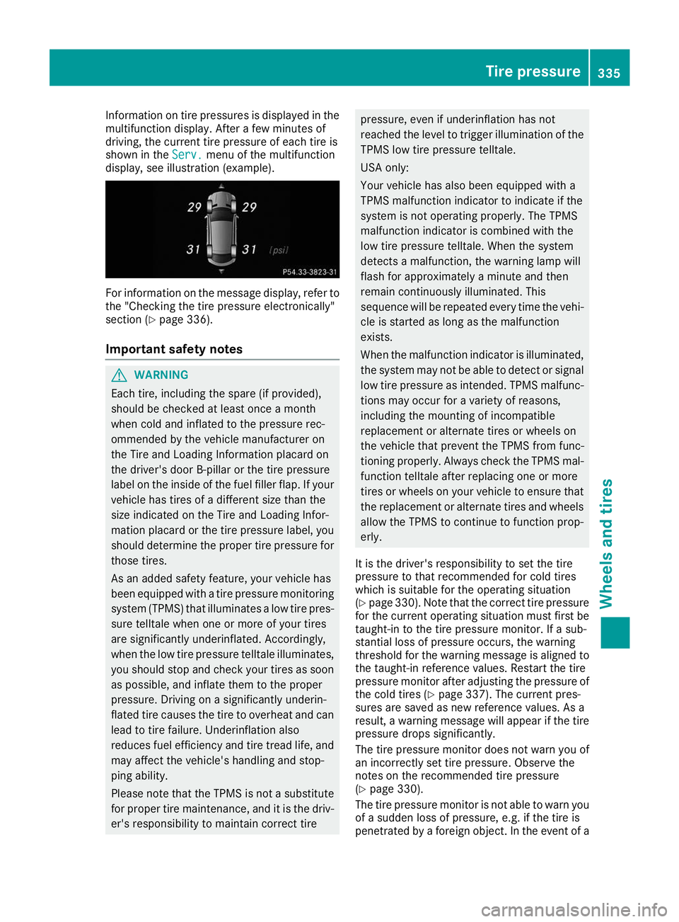
Information on tire pressures is displayed in the
multifunction display. After a few minutes of
driving, the current tire pressure of each tire is
shown in the Serv.
Serv. menu of the multifunction
display, see illustration (example). For information on the message display, refer to
the "Checking the tire pressure electronically"
section (Y page 336).
Important safety notes G
WARNING
Each tire, including the spare (if provided),
should be checked at least once a month
when cold and inflated to the pressure rec-
ommended by the vehicle manufacturer on
the Tire and Loading Information placard on
the driver's door B-pillar or the tire pressure
label on the inside of the fuel filler flap. If your vehicle has tires of a different size than the
size indicated on the Tire and Loading Infor-
mation placard or the tire pressure label, you should determine the proper tire pressure for
those tires.
As an added safety feature, your vehicle has
been equipped with a tire pressure monitoring system (TPMS) that illuminates a low tire pres-
sure telltale when one or more of your tires
are significantly underinflated. Accordingly,
when the low tire pressure telltale illuminates,
you should stop and check your tires as soon
as possible, and inflate them to the proper
pressure. Driving on a significantly underin-
flated tire causes the tire to overheat and can lead to tire failure. Underinflation also
reduces fuel efficiency and tire tread life, and may affect the vehicle's handling and stop-
ping ability.
Please note that the TPMS is not a substitute
for proper tire maintenance, and it is the driv-
er's responsibility to maintain correct tire pressure, even if underinflation has not
reached the level to trigger illumination of the
TPMS low tire pressure telltale.
USA only:
Your vehicle has also been equipped with a
TPMS malfunction indicator to indicate if the
system is not operating properly. The TPMS
malfunction indicator is combined with the
low tire pressure telltale. When the system
detects a malfunction, the warning lamp will
flash for approximately a minute and then
remain continuously illuminated. This
sequence will be repeated every time the vehi-
cle is started as long as the malfunction
exists.
When the malfunction indicator is illuminated,
the system may not be able to detect or signal low tire pressure as intended. TPMS malfunc-tions may occur for a variety of reasons,
including the mounting of incompatible
replacement or alternate tires or wheels on
the vehicle that prevent the TPMS from func-
tioning properly. Always check the TPMS mal-
function telltale after replacing one or more
tires or wheels on your vehicle to ensure that
the replacement or alternate tires and wheels
allow the TPMS to continue to function prop-
erly.
It is the driver's responsibility to set the tire
pressure to that recommended for cold tires
which is suitable for the operating situation
(Y page 330). Note that the correct tire pressure
for the current operating situation must first be
taught-in to the tire pressure monitor. If a sub-
stantial loss of pressure occurs, the warning
threshold for the warning message is aligned to the taught-in reference values. Restart the tire
pressure monitor after adjusting the pressure of
the cold tires (Y page 337). The current pres-
sures are saved as new reference values. As a
result, a warning message will appear if the tire
pressure drops significantly.
The tire pressure monitor does not warn you of
an incorrectly set tire pressure. Observe the
notes on the recommended tire pressure
(Y page 330).
The tire pressure monitor is not able to warn you of a sudden loss of pressure, e.g. if the tire is
penetrated by a foreign object. In the event of a Tire pressure
335Wheels and tires Z
Page 340 of 370
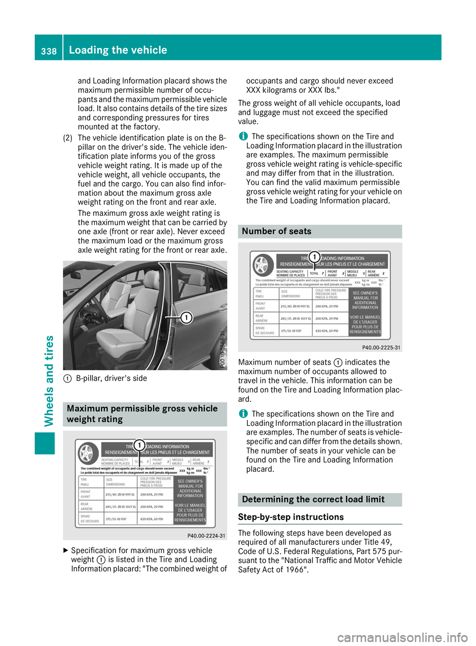
and Loading Information placard shows the
maximum permissible number of occu-
pants and the maximum permissible vehicle
load. It also contains details of the tire sizes and corresponding pressures for tires
mounted at the factory.
(2) The vehicle identification plate is on the B- pillar on the driver's side. The vehicle iden-
tification plate informs you of the gross
vehicle weight rating. It is made up of the
vehicle weight, all vehicle occupants, the
fuel and the cargo. You can also find infor-
mation about the maximum gross axle
weight rating on the front and rear axle.
The maximum gross axle weight rating is
the maximum weight that can be carried by one axle (front or rear axle). Never exceed
the maximum load or the maximum gross
axle weight rating for the front or rear axle. 0043
B-pillar, driver's side Maximum permissible gross vehicle
weight rating X
Specification for maximum gross vehicle
weight 0043is listed in the Tire and Loading
Information placard: "The combined weight of occupants and cargo should never exceed
XXX kilograms or XXX lbs."
The gross weight of all vehicle occupants, load
and luggage must not exceed the specified
value.
i The specifications shown on the Tire and
Loading Information placard in the illustration are examples. The maximum permissible
gross vehicle weight rating is vehicle-specific
and may differ from that in the illustration.
You can find the valid maximum permissible
gross vehicle weight rating for your vehicle on
the Tire and Loading Information placard. Number of seats
Maximum number of seats
0043indicates the
maximum number of occupants allowed to
travel in the vehicle. This information can be
found on the Tire and Loading Information plac-
ard.
i The specifications shown on the Tire and
Loading Information placard in the illustration
are examples. The number of seats is vehicle- specific and can differ from the details shown.
The number of seats in your vehicle can be
found on the Tire and Loading Information
placard. Determining the correct load limit
Step-by-step instructions The following steps have been developed as
required of all manufacturers under Title 49,
Code of U.S. Federal Regulations, Part 575 pur-
suant to the "National Traffic and Motor Vehicle
Safety Act of 1966". 338
Loading the vehicleWheels and tires
Page 341 of 370
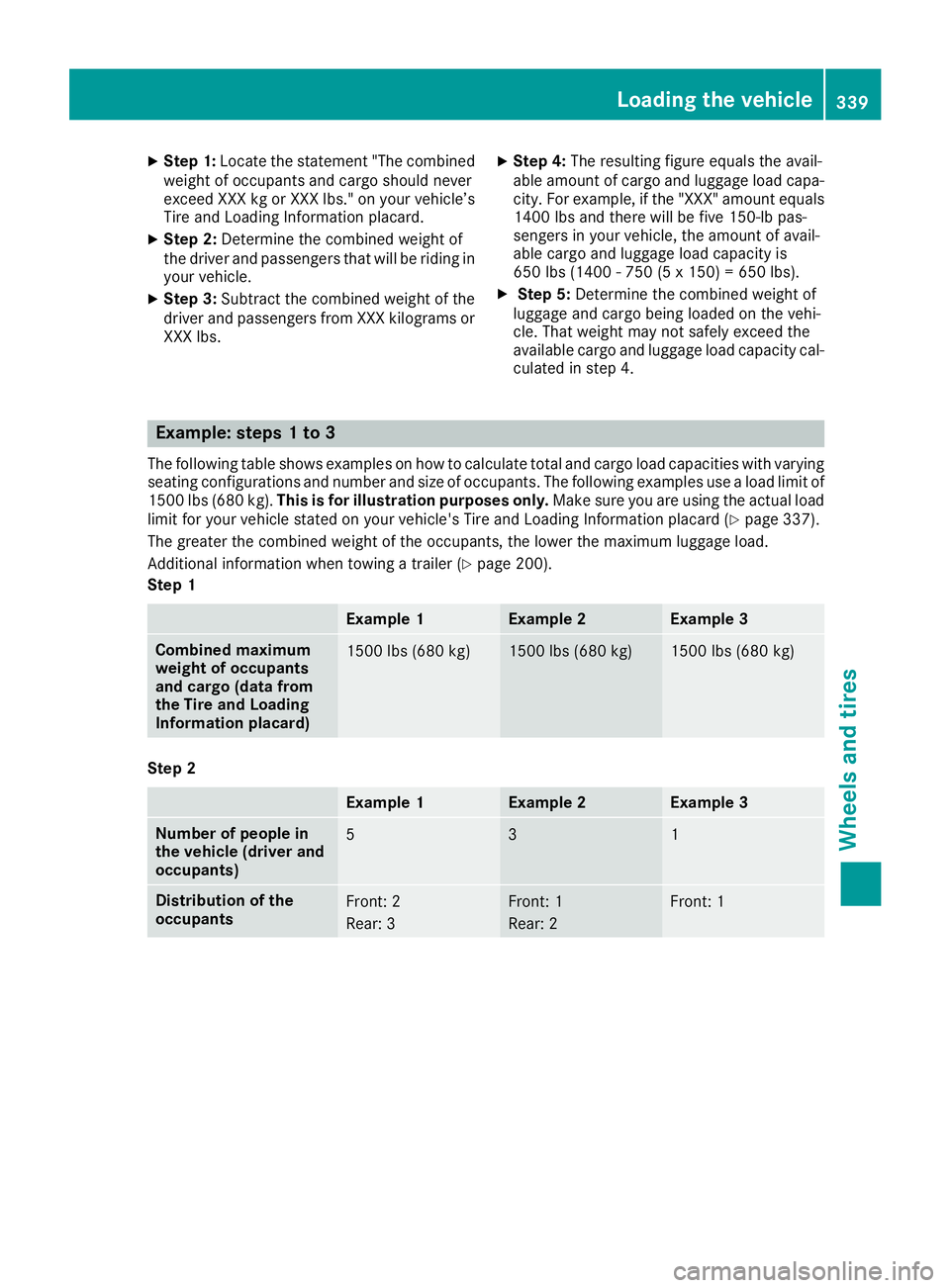
X
Step 1: Locate the statement "The combined
weight of occupants and cargo should never
exceed XXX kg or XXX lbs." on your vehicle’s
Tire and Loading Information placard.
X Step 2: Determine the combined weight of
the driver and passengers that will be riding in
your vehicle.
X Step 3: Subtract the combined weight of the
driver and passengers from XXX kilograms or
XXX lbs. X
Step 4: The resulting figure equals the avail-
able amount of cargo and luggage load capa- city. For example, if the "XXX" amount equals
1400 lbs and there will be five 150-lb pas-
sengers in your vehicle, the amount of avail-
able cargo and luggage load capacity is
650 lbs (1400 - 750 (5 x 150) = 650 lbs).
X Step 5: Determine the combined weight of
luggage and cargo being loaded on the vehi-
cle. That weight may not safely exceed the
available cargo and luggage load capacity cal- culated in step 4. Example: steps 1 to 3
The following table shows examples on how to calculate total and cargo load capacities with varying seating configurations and number and size of occupants. The following examples use a load limit of
1500 lbs (680 kg). This is for illustration purposes only. Make sure you are using the actual load
limit for your vehicle stated on your vehicle's Tire and Loading Information placard (Y page 337).
The greater the combined weight of the occupants, the lower the maximum luggage load.
Additional information when towing a trailer (Y page 200).
Step 1 Example 1 Example 2 Example 3
Combined maximum
weight of occupants
and cargo (data from
the Tire and Loading
Information placard)
1500 lbs (680 kg) 1500 lbs (680 kg) 1500 lbs (680 kg)
Step 2
Example 1 Example 2 Example 3
Number of people in
the vehicle (driver and
occupants)
5 3 1
Distribution of the
occupants
Front: 2
Rear: 3 Front: 1
Rear: 2 Front: 1Loading the vehicle
339Wheels and tires Z