MERCEDES-BENZ GLE COUPE 2019 Owners Manual
Manufacturer: MERCEDES-BENZ, Model Year: 2019, Model line: GLE COUPE, Model: MERCEDES-BENZ GLE COUPE 2019Pages: 697, PDF Size: 11.6 MB
Page 271 of 697
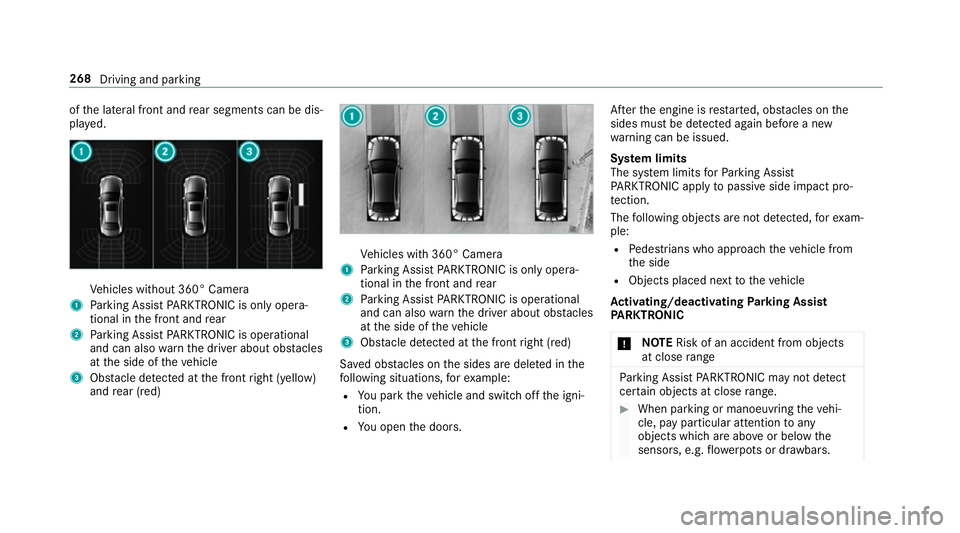
of
the lateral front and rear segments can be dis‐
pla yed. Ve
hicles without 360° Camera
1 Parking Assist PARKTRONIC is on ly opera‐
tional in the front and rear
2 Parking Assist PARKTRONIC is operational
and can also warnthe driver about obs tacles
at the side of theve hicle
3 Obstacle de tected at the front right (yellow)
and rear (red) Ve
hicles with 360° Camera
1 Parking Assist PARKTRONIC is on ly opera‐
tional in the front and rear
2 Parking Assist PARKTRONIC is operational
and can also warnthe driver about obs tacles
at the side of theve hicle
3 Obstacle de tected at the front right (red)
Sa ved obs tacles on the sides are dele ted in the
fo llowing situations, forex ample:
R You park theve hicle and switch off the igni‐
tion.
R You open the doors. Af
terth e engine is restar ted, obs tacles on the
sides must be de tected again before a new
wa rning can be issued.
Sy stem limits
The sy stem limits forPa rking Assist
PA RKTRONIC apply topassive side impact pro‐
te ction.
The following objects are not de tected, forex am‐
ple:
R Pedestrians who approach theve hicle from
th e side
R Objects placed next totheve hicle
Ac tivating/deactivating Parking Assist
PA RKTRONIC
* NO
TERisk of an accident from objects
at close range Pa
rking Assist PARKTRONIC may not de tect
cer tain objects at close range. #
When pa rking or manoeuvring theve hi‐
cle, pay particular attention toany
objects which are abo veor below the
sensors, e.g. flowe rpots or dr awbars. 268
Driving and parking
Page 272 of 697
The
vehicle or other objects could oth‐
erwise be damaged. If
th eé symbol is shown in the multifunction
displa y,Pa rking Assist PARKTRONIC is not
active.
Multimedia sy stem:
4 Settings 5
Quick access
5 PARKTRONIC #
Activate or deacti vate the function.
% Parking Assist PARKTRONIC is automatical ly
activated when theve hicle is star ted.
Ad justing the warning tones of Parking
Assist PARKTRONIC
Multimedia sy stem:
4 © 5
Settings 5
Assistance
5 Camera & parking 5
Set warning tone
Ad justing the volume of thewa rning tones #
Select Warning tone volume. #
Set a value. Ad
justing the pitch of the warning tones #
Select Warning tone pitch. #
Set a value.
Specifying thest arting point for the warning
to nes
Yo u can specify whe ther thePa rking Assist
PA RKTRONIC warning tones should commence
when theve hicle is fur ther aw ay from an obs ta‐
cle. #
Select Warn early all-round. #
Activate or deacti vate the function.
Ac tivating/deactivating audio fadeout
Yo u can specify whe ther thevo lume of a media
source in the multimedia sy stem is tobe
re duced when Parking Assist PARKTRONIC
sounds a warning tone. #
Select Audio fadeout during warning tones. #
Activate or deacti vate the function. Fu
nction of Trailer Manoeuvring Assist
* NO
TEDama getotraile rswith a stabilisa‐
tion device against swerving In
the case of trailers with a stabilisation
device against swerving, the trailer or trailer
to w hit chcould be damaged. #
If a trailer coupling wi thTrailer Manoeu‐
vring Assist is used, on lyuse trailers
without a stabilisation device against
swerving. *
NO
TEDama gedue to ov erhanging loads
in front or dr awbar ins tallations The
vehicle and the trailer may be damaged
during manoeuvring due toove rhanging
loads at the front of the trailer or dr awbar
ins tallations. #
Pay attention to overhanging loads or
dr aw bar ins tallations while manoeu‐
vring. Tr
ailer Manoeuv ring Assi stassists you when
re ve rsing with a trailer. By means of a turning Driving and parking
269
Page 273 of 697
angle sensor in
the trailer coupling, Trailer
Manoeuv ring Assi stmonitors the articulation
angle between theve hicle and trailer and
adjusts it toa specified value.
Yo u can either en terth e articulation angle value
directly via the multimedia sy stem or use a
st ra ightening manoeuvre. When car rying out a
st ra ightening manoeuvre, the sy stem calculates
th e articulation angle automatically and stra ight‐
ens theve hicle/trailer combination tothe trail‐
er's cur rent di rection.
Tr ailer Manoeuv ring Assi stmust be taught-in
before it can adjust the articulation angle
(/ page 270).
Obse rveth e no tes on towing a trailer
(/ page 296).
Sy stem limits
The sy stem may be impaired or may not function
in thefo llowing situations:
R The gradient is more than appr oximately
15 %.
Using Trailer Manoeuvring Assist
Re quirements: R
The vehicle has been star ted.
R A trailer has been de tected.
Te aching-in Trailer Manoeuvring Assist #
Drive forw ards a short dis tance wi th the car/
trailer combination.
The comple tedte ach-in process is shown in
th e media displa y.
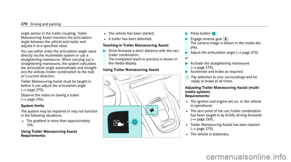
Using Trailer Manoeuvring Assist #
Press button 1. #
Engage reve rsege ar k.
The camera image is shown in the media dis‐
pla y. #
Adjust the articulation angle (/ page270).
or #
Activate thest ra ightening manoeuvre
(/ page 270). #
Accelerate and brake as requ ired.
% Pay attention toyour sur roundings and be
re ady tobrake at all times.
Ad justing Trailer Manoeuvring Assist (multi‐
media sy stem)
Re quirements:
R The ignition and engine are on, or theve hicle
is operational.
R The zero point of the car/t railer combination
has been taught-in bybrief lydriving forw ards
(/ page 269).
R Trailer Manoeuv ring Assi sthas been star ted
( / page 270).
R The vehicle is stationar y. 270
Driving and pa rking
Page 274 of 697
R
The gradient is less than appr oximately 15%.
Ad justing the articulation angle of the trailer #
Select ¸.
The articulation angle can be changed on the
media display or on theto uchpad. #
Swipe left or right tochange the articulation
angle.
% The maximum articulation angle depends on
the length of the trailer. This is calculated by
th e sy stem bydriving theve hicle forw ards,
including cornering. Before the length of the
trailer has been calculated, the maximum
articulation angle is appr oximately 23°. The
longer the trailer is, the higher the maximum
articulation angle (max. appr oximately 60°). #
Set the desired articulation angle.
When the articulation angle entered has been
re ached, the dr awbar is loc kedby the sy stem so
th at the angle is maintained. Ac
tivating the stra ightening manoeuvre #
Select º.
The sy stem calculates the articulation angle
in such a wayth at the direction of the trailer
at the time of activation is maintained. There
is a short counter steering mo vement of the
trailer while theve hicle is reve rsed, which
th en guides it back tothe desired line. In this
wa y,theve hicle is aligned stra ight with the
trailer and, at the same time, the direction of
th e trailer is maintained. Re
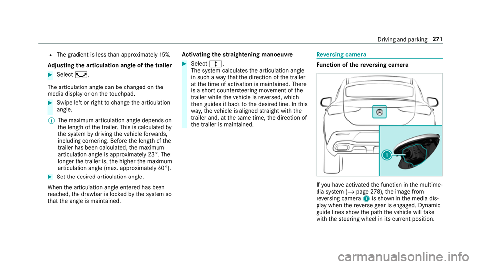
versing camera Fu
nction of there ve rsing camera If
yo u ha veactivated the function in the multime‐
dia sy stem (/ page278), the image from
re ve rsing camera 1is shown in the media dis‐
play when there ve rsege ar is engaged. Dynamic
guide lines show the path theve hicle will take
with thesteering wheel in its cur rent position. Driving and pa
rking 271
Page 275 of 697
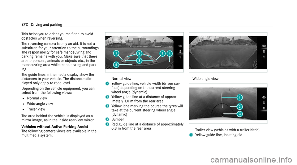
This helps
youto orient yourself and to avoid
obs tacles when reve rsing.
The reve rsing camera is only an aid. It is not a
substitute foryo ur attention tothe sur roundings.
The responsibility for safe manoeuvring and
parking remains with you. Make sure that there
are no persons, animals or objects etc., in the
manoeuvring area while manoeuvring and park‐
ing.
The guide lines in the media display show the
dis tances to yourvehicle. The dis tances dis‐
pl ay ed only apply toroad le vel.
Depending on theve hicle equipment, you can
select from thefo llowing vie ws:
R Normal view
R Wide-angle view
R Trailer view
The area behind theve hicle is displa yed as a
mir ror image, as in the inside rearview mir ror.
Ve hicles without Active Parking Assist
The following camera vie wsare available in the
multimedia sy stem: Normal view
1 Yellow guide line, vehicle width (driven sur‐
fa ce) depending on the cur rent steering
wheel angle (dynamic)
2 Yellow guide line at a dis tance of appr ox‐
imately 1.0 m from there ar area
3 Yellow lane marking the course the tyres will
ta ke atthe cur rent steering wheel angle
(dynamic)
4 Bumper
5 Red guide line at a dis tance of appr oximately
0.3 m from there ar area Wi
de-angle view Tr
ailer view (vehicles with a trailer hit ch)
1 Yellow guide line, locating aid 272
Driving and pa rking
Page 276 of 697
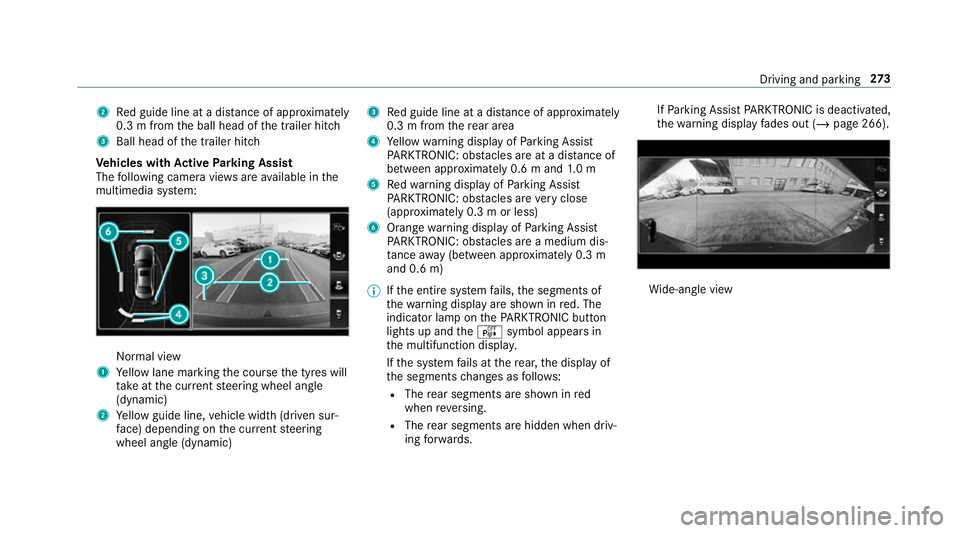
2
Red guide line at a dis tance of appr oximately
0.3 m from the ball head of the trailer hitch
3 Ball head of the trailer hitch
Ve hicles with Active Parking Assist
The following camera vie wsare available in the
multimedia sy stem: Normal view
1 Yellow lane marking the course the tyres will
ta ke atthe cur rent steering wheel angle
(dynamic)
2 Yellow guide line, vehicle width (driven sur‐
fa ce) depending on the cur rent steering
wheel angle (dynamic) 3
Red guide line at a dis tance of appr oximately
0.3 m from there ar area
4 Yellow warning display of Parking Assist
PA RKTRONIC: obstacles are at a dis tance of
between appr oximately 0.6 m and 1.0 m
5 Redwa rning display of Parking Assist
PA RKTRONIC: obstacles are very close
(appr oximately 0.3 m or less)
6 Orange warning display of Parking Assist
PA RKTRONIC: obstacles are a medium dis‐
ta nce away (between appr oximately 0.3 m
and 0.6 m)
% Ifth e entire sy stem fails, the segments of
th ewa rning display are shown in red. The
indicator lamp on thePA RKTRONIC but ton
lights up and theé symbol appears in
th e multifunction displa y.
If th e sy stem fails at there ar, the display of
th e segments changes as follo ws:
R The rear segments are shown in red
when reve rsing.
R The rear segments are hidden when driv‐
ing forw ards. If
Pa rking Assist PARKTRONIC is deacti vated,
th ewa rning display fades out (/ page 266). Wi
de-angle view Driving and parking
273
Page 277 of 697
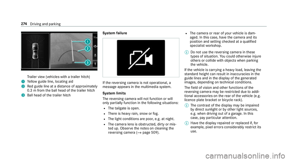
Tr
ailer view (vehicles with a trailer hit ch)
1 Yellow guide line, locating aid
2 Red guide line at a dis tance of appr oximately
0.3 m from the ball head of the trailer hitch
3 Ball head of the trailer hitch Sy
stem failure If
th ere ve rsing camera is not operational, a
message appears in the multimedia sy stem.
Sy stem limits
The reve rsing camera will not function or will
only partially function in thefo llowing situations:
R The tailgate is open.
R There is heavy rain, snow or fog.
R The light conditions are poor, e.g. at night.
R The camera lens is obstructed, dirty or mis‐
ted up. Obser vethe no tes on cleaning the
re ve rsing camera (/ page 509). R
The camera or rear of your vehicle is dam‐
aged. In this case, ha vethe camera and its
position and setting checked at a qualified
specialist workshop.
% Do not use there ve rsing camera in these
types of situation. You could otherwise injure
ot hers or collide with objects when parking
th eve hicle.
If th eve hicle is car rying a heavy load, leaving the
st andard height can result in inaccuracies in the
guide lines and in the display of thege nerated
ima ges, depending on tech nical conditions.
The field of vision and other functions of the
re ve rsing camera may be restricted due toaddi‐
tional accesso ries on there ar of theve hicle (e.g.
licence plate brac ket or bicycle rack ).
% The contrast of the display may be impaired
by direct sunlight or by other light sources,
e.g. when driving out of a garage . In this
case, pay particular attention.
% Have the display repaired or replaced if, for
ex ample, pixel er rors considerably restrict its
use. 274
Driving and pa rking
Page 278 of 697
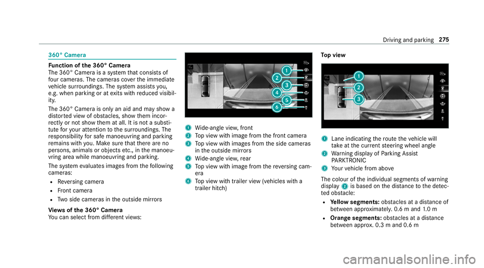
360° Camera
Fu
nction of the 360° Camera
The 360° Camera is a sy stem that consists of
fo ur cameras. The cameras co verth e immediate
ve hicle sur roundings. The sy stem assists you,
e.g. when parking or at exits with reduced visibil‐
ity.
The 360° Camera is only an aid and may show a
dis torted view of obs tacles, show them incor‐
re ctly or not show them at all. It is not a substi‐
tute foryo ur attention tothe sur roundings. The
re sponsibility for safe manoeuvring and parking
re mains with you. Make sure that there are no
persons, animals or objects etc., in the manoeu‐
vring area while manoeuvring and parking.
The sy stem evaluates images from thefo llowing
cameras:
R Reversing camera
R Front camera
R Two side cameras in the outside mir rors
Vi ew s of the 360° Camera
Yo u can select from dif fere nt vie ws: 1
Wide-angle vie w,front
2 Top view with image from the front camera
3 Top view with images from the side cameras
in the outside mir rors
4 Wide-angle vie w,rear
5 Top view with image from there ve rsing cam‐
era
6 Top view with trailer view (vehicles with a
trailer hitch) To
p view 1
Lane indicating thero ute theve hicle will
ta ke atthe cur rent steering wheel angle
2 Warning display of Parking Assist
PA RKTRONIC
3 Your vehicle from abo ve
The colour of the individual segments of warning
display 2is based on the dis tance tothe de tec‐
te d obs tacle:
R Yellow segments: obstacles at a di stance of
between appr oximatel y.0.6 m and 1.0 m
R Orange segments: obstacles at a di stance
between appr ox. 0.3 m and 0.6 m Driving and pa
rking 275
Page 279 of 697
R
Red segments: obstacles at a very short
dis tance of appr ox. 0.3 m or less
When Parking Assist PARKTRONIC is operational
and no object is de tected, the segments of the
wa rning display are shown in gr ey.
% Ifth e entire sy stem fails, the segments of
th ewa rning display are shown in red. The
indicator lamp on thePA RKTRONIC but ton
lights up and theé symbol appears in
th e multifunction displa y.
If th e sy stem fails at there ar, the display of
th e segments changes as follo ws:
R The rear segments are shown in red
when reve rsing.
R The rear segments are hidden when driv‐
ing forw ards.
If Pa rking Assist PARKTRONIC is deacti vated,
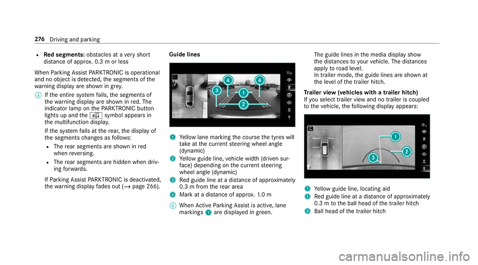
th ewa rning display fades out (/ page 266). Guide lines
1
Yellow lane marking the course the tyres will
ta ke atthe cur rent steering wheel angle
(dynamic)
2 Yellow guide line, vehicle width (driven sur‐
fa ce) depending on the cur rent steering
wheel angle (dynamic)
3 Red guide line at a dis tance of appr oximately
0.3 m from there ar area
4 Mark at a dis tance of appr ox.1. 0 m
% When Active Parking Assist is active, lane
markings 1are displa yed in green. The guide lines in
the media display show
th e dis tances to yourvehicle. The dis tances
apply toroad le vel.
In trailer mode, the guide lines are shown at
th e le vel of the trailer hitch.
Tr ailer view (vehicles with a trailer hitch)
If yo u select trailer view and no trailer is coupled
to theve hicle, thefo llowing display appears: 1
Yellow guide line, locating aid
2 Red guide line at a dis tance of appr oximately
0.3 m tothe ball head of the trailer hitch
3 Ball head of the trailer hitch 276
Driving and pa rking
Page 280 of 697
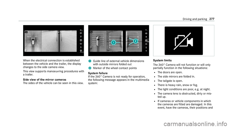
When
the electrical connection is es tablished
between theve hicle and the trailer, the display
ch anges tothe side camera vie w.
This view supports manoeuvring procedures with
a trailer.
Side view of the mir ror cameras
The sides of theve hicle can be seen in this vie w. 1
Guide line of extern al vehicle dimensions
with outside mir rors folded out
2 Marker of the wheel conta ct points
Sy stem failure
If th e 360° Camera is not ready for operation,
th efo llowing message appears in the multimedia
sy stem: Sy
stem limits
The 360° Camera will not function or will only
partially function in thefo llowing situations:
R The doors are open.
R The side mir rors are folded in.
R The tailgate is open.
R There is heavy rain, snow or fog.
R The light conditions are poor, e.g. at night.
R The camera lens is obstructed, dirty or mis‐
ted up.
R If cameras or vehicle components in which
th e cameras are fitted are dama ged. In this
eve nt, ha vethe cameras, their positions and Driving and parking
277