service indicator MERCEDES-BENZ GLE SUV 2019 Owner's Manual
[x] Cancel search | Manufacturer: MERCEDES-BENZ, Model Year: 2019, Model line: GLE SUV, Model: MERCEDES-BENZ GLE SUV 2019Pages: 398, PDF Size: 12.25 MB
Page 4 of 398
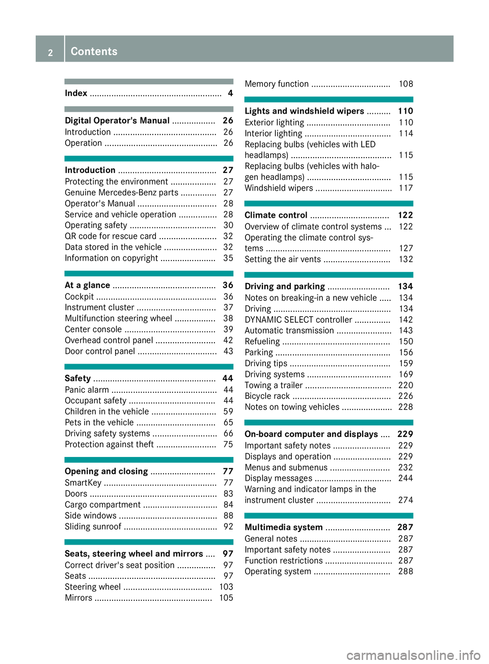
Index
....................................................... 4Digital Operator's Manual
..................26
Introduction .......................................... .26
Operation ............................................... 26 Introduction
......................................... 27
Protecting the environment ...................27
Genuine Mercedes-Benz parts .............. .27
Operator's Manual ................................. 28
Service and vehicle operation ................28
Operating safety .................................... 30
QR code for rescue card ........................ 32
Data stored in the vehicle ......................32
Information on copyright ....................... 35 At a glance
........................................... 36
Cockpit .................................................. 36
Instrument cluster .................................37
Multifunction steering wheel ................. 38
Center console ...................................... 39
Overhead control panel .........................42
Door control panel ................................. 43 Safety
................................................... 44
Panic alarm ............................................ 44
Occupant safety .................................... 44
Children in the vehicle ........................... 59
Pets in the vehicle ................................. 65
Driving safety systems ........................... 66
Protection against theft ........................ .75Opening and closing
...........................77
SmartKey ............................................... 77
Doors ..................................................... 83
Cargo compartment ...............................84
Side windows ......................................... 88
Sliding sunroof ....................................... 92 Seats, steering wheel and mirrors
....97
Correct driver's seat position ................ 97
Seats ..................................................... 97
Steering wheel ..................................... 103
Mirrors ................................................. 105 Memory function ................................. 108 Lights and windshield wipers
..........110
Exterior lighting ................................... 110
Interior lighting .................................... 114
Replacing bulbs (vehicles with LED
headlamps) .......................................... 115
Replacing bulbs (vehicles with halo-
gen headlamps) ................................... 115
Windshield wipers ................................ 117 Climate control
................................. 122
Overview of climate control systems ... 122
Operating the climate control sys-
tems .................................................... 127
Setting the air vents ............................ 132 Driving and parking
..........................134
Notes on breaking-in a new vehicle ..... 134
Driving ................................................. 134
DYNAMIC SELECT controller ............... 142
Automatic transmission ....................... 143
Refueling ............................................. 150
Parking ................................................ 156
Driving tips .......................................... 159
Driving systems ................................... 169
Towing a trailer .................................... 220
Bicycle rack ......................................... 226
Notes on towing vehicles ..................... 228 On-board computer and displays
....229
Important safety notes ........................ 229
Displays and operation ........................ 229
Menus and submenus ......................... 232
Display messages ................................ 244
Warning and indicator lamps in the
instrument cluster ............................... 274 Multimedia system
...........................287
General notes ...................................... 287
Important safety notes ........................ 287
Function restrictions ............................ 287
Operating system ................................ 288 2
Contents
Page 7 of 398
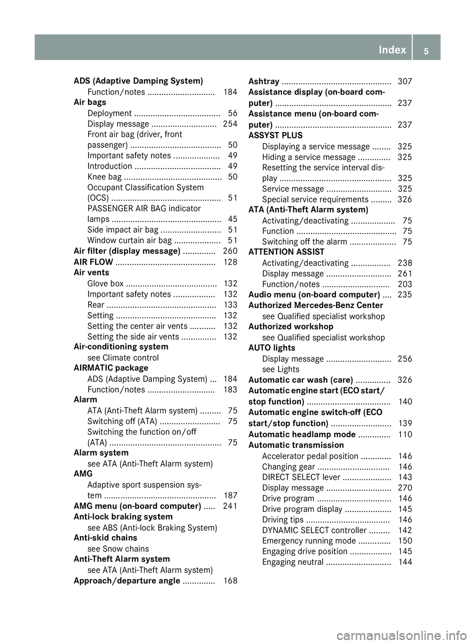
ADS (Adaptive Damping System)
Function/notes ............................ .184
Air bags
Deployment ..................................... 56
Display message ............................ 254
Front air bag (driver, front
passenger) ....................................... 50
Important safety notes .................... 49
Introduction ..................................... 49
Knee bag .......................................... 50
Occupant Classification System
(OCS) ............................................... 51
PASSENGER AIR BAG indicator
lamps ............................................... 45
Side impact air bag .......................... 51
Window curtain air bag .................... 51
Air filter (display message) .............. 260
AIR FLOW .......................................... .128
Air vents
Glove box ....................................... 132
Important safety notes .................. 132
Rear ............................................... 133
Setting .......................................... .132
Setting the center air vents ........... 132
Setting the side air vents .............. .132
Air-conditioning system
see Climate control
AIRMATIC package
ADS (Adaptive Damping System) ... 184
Function/notes ............................ .183
Alarm
ATA (Anti-Theft Alarm system) ......... 75
Switching off (ATA) .......................... 75
Switching the function on/off
(ATA) ................................................ 75
Alarm system
see ATA (Anti-Theft Alarm system)
AMG
Adaptive sport suspension sys-
tem ................................................ 187
AMG menu (on-board computer) ..... 241
Anti-lock braking system
see ABS (Anti-lock Braking System)
Anti-skid chains
see Snow chains
Anti-Theft Alarm system
see ATA (Anti-Theft Alarm system)
Approach/departure angle .............. 168Ashtray
............................................... 307
Assistance display (on-board com-
puter) ................................................. .237
Assistance menu (on-board com-
puter) ................................................. .237
ASSYST PLUS
Displaying a service message ....... .325
Hiding a service message .............. 325
Resetting the service interval dis-
pla y................................................ 325
Service message ............................ 325
Special service requirements ......... 326
ATA (Anti-Theft Alarm system)
Activating/deactivating ................... 75
Function ........................................... 75
Switching off the alarm .................... 75
ATTENTION ASSIST
Activating/deactivating ................. 238
Display message ............................ 261
Function/note s............................. 203
Audio menu (on-board computer) .... 235
Authorized Mercedes-Benz Center
see Qualified specialist workshop
Authorized workshop
see Qualified specialist workshop
AUTO lights
Display message ............................ 256
see Lights
Automatic car wash (care) ............... 326
Automatic engine start (ECO start/
stop function) .................................... 140
Automatic engine switch-off (ECO
start/stop function) .......................... 139
Automatic headlamp mode .............. 110
Automatic transmission
Accelerator pedal position ............. 146
Changing gear ............................... 146
DIRECT SELECT lever ..................... 143
Display message ............................ 270
Drive program ................................ 146
Drive program display .................... 145
Driving tips .................................... 146
DYNAMIC SELECT controlle r......... 142
Emergency running mode .............. 150
Engaging drive position .................. 145
Engaging neutral ............................ 144 Index
5
Page 24 of 398
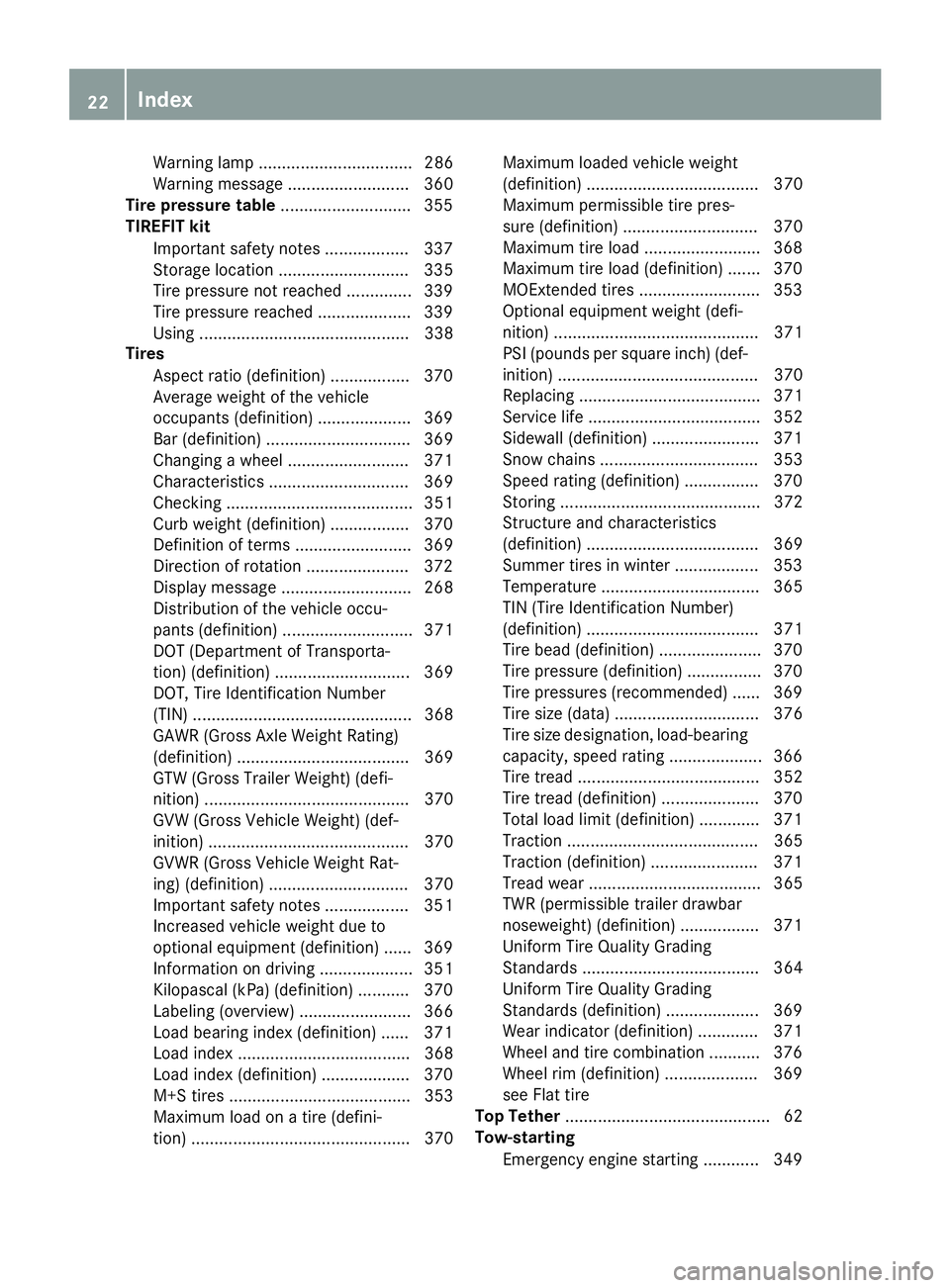
Warning lamp ................................. 286
Warning message .......................... 360
Tire pressure table ............................355
TIREFIT kit
Important safety notes .................. 337
Storage location ............................ 335
Tire pressure not reached .............. 339
Tire pressure reached .................... 339
Using ............................................. 338
Tires
Aspect ratio (definition) ................. 370
Average weight of the vehicle
occupants (definition) .................... 369
Bar (definition) ............................... 369
Changing a wheel .......................... 371
Characteristics .............................. 369
Checking ........................................ 351
Curb weight (definition) ................. 370
Definition of terms ......................... 369
Direction of rotatio n...................... 372
Display message ............................ 268
Distribution of the vehicle occu-
pants (definition) ............................ 371
DOT (Department of Transporta-
tion) (definition) ............................. 369
DOT, Tire Identification Number
(TIN) ............................................... 368
GAWR (Gross Axle Weight Rating)
(definition) ..................................... 369
GTW (Gross Trailer Weight) (defi-
nition) ............................................ 370
GVW (Gross Vehicle Weight) (def-
inition) ........................................... 370
GVWR (Gross Vehicle Weight Rat-
ing) (definition) .............................. 370
Important safety notes .................. 351
Increased vehicle weight due to
optional equipment (definition) ...... 369
Information on driving .................... 351
Kilopascal (kPa) (definition) ........... 370
Labeling (overview) ........................ 366
Load bearing index (definition) ...... 371
Load index ..................................... 368
Load index (definition) ................... 370
M+S tire s....................................... 353
Maximum load on a tire (defini-
tion) ............................................... 370 Maximum loaded vehicle weight
(definition) ..................................... 370
Maximum permissible tire pres-
sure (definition) ............................. 370
Maximum tire load ......................... 368
Maximum tire load (definition) ....... 370
MOExtended tire s.......................... 353
Optional equipment weight (defi-
nition) ............................................ 371
PSI (pounds per square inch) (def-
inition) ........................................... 370
Replacing ....................................... 371
Service life ..................................... 352
Sidewall (definition) ....................... 371
Snow chains .................................. 353
Speed rating (definition) ................ 370
Storing ........................................... 372
Structure and characteristics
(definition) ..................................... 369
Summer tires in winter .................. 353
Temperature .................................. 365
TIN (Tire Identification Number)
(definition) ..................................... 371
Tire bead (definition) ...................... 370
Tire pressure (definition) ................ 370
Tire pressures (recommended) ...... 369
Tire size (data) ............................... 376
Tire size designation, load-bearing capacity, speed rating .................... 366
Tire tread ....................................... 352
Tire tread (definition) ..................... 370
Total load limit (definition) ............. 371
Traction ......................................... 365
Traction (definition) ....................... 371
Tread wear ..................................... 365
TWR (permissible trailer drawbar
noseweight) (definition) ................. 371
Uniform Tire Quality Grading
Standards ...................................... 364
Uniform Tire Quality Grading
Standards (definition) .................... 369
Wear indicator (definition) ............. 371
Wheel and tire combination ........... 376
Wheel rim (definition) .................... 369
see Flat tire
Top Tether ............................................ 62
Tow-starting
Emergency engine starting ............ 349 22
Index
Page 78 of 398
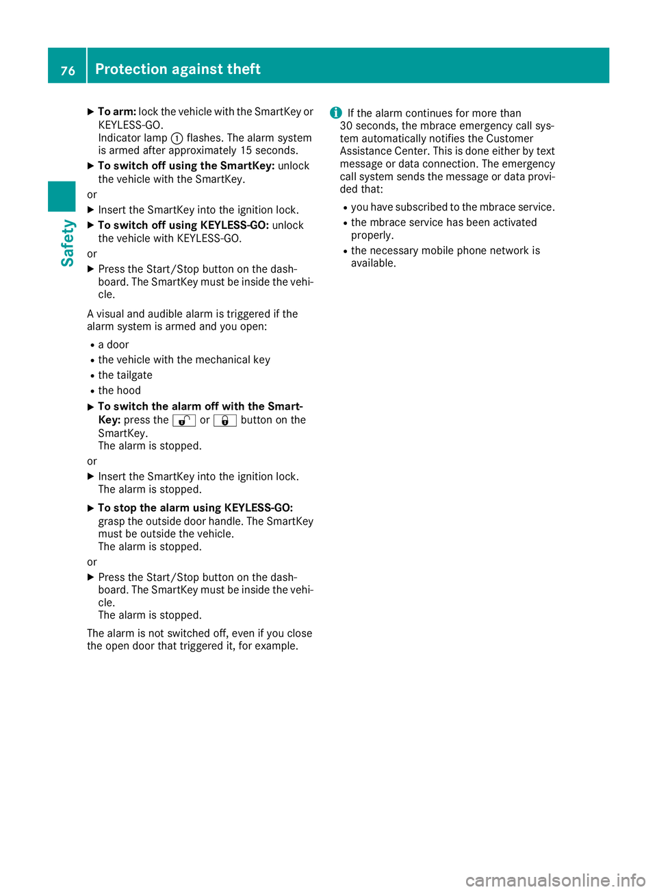
X
To arm: lock the vehicle with the SmartKey or
KEYLESS-GO.
Indicator lamp 0043flashes. The alarm system
is armed after approximately 15 seconds.
X To switch off using the SmartKey: unlock
the vehicle with the SmartKey.
or X Insert the SmartKey into the ignition lock.
X To switch off using KEYLESS-GO: unlock
the vehicle with KEYLESS-GO.
or X Press the Start/Stop button on the dash-
board. The SmartKey must be inside the vehi-
cle.
A visual and audible alarm is triggered if the
alarm system is armed and you open:
R a door
R the vehicle with the mechanical key
R the tailgate
R the hood
X To switch the alarm off with the Smart-
Key:
press the 0036or0037 button on the
SmartKey.
The alarm is stopped.
or X Insert the SmartKey into the ignition lock.
The alarm is stopped.
X To stop the alarm using KEYLESS-GO:
grasp the outside door handle. The SmartKey
must be outside the vehicle.
The alarm is stopped.
or X Press the Start/Stop button on the dash-
board. The SmartKey must be inside the vehi-
cle.
The alarm is stopped.
The alarm is not switched off, even if you close
the open door that triggered it, for example. i
If the alarm continues for more than
30 seconds, the mbrace emergency call sys-
tem automatically notifies the Customer
Assistance Center. This is done either by text
message or data connection. The emergency call system sends the message or data provi-ded that:
R you have subscribed to the mbrace service.
R the mbrace service has been activated
properly.
R the necessary mobile phone network is
available. 76
Protection against theftSafety
Page 312 of 398
mbrace
General notes The mbrace system is only available in the USA.
A license agreement must be in place in order to
activate the mbrace service. Make sure that
your system is activated and operational. To
register, press the 00D9Info call button. If any of
the steps mentioned are not carried out, the
system may not be activated.
If you have questions about the activation, con- tact one of the following telephone hotlines:
Mercedes-Benz Customer Assistance Center at
1-800 FOR-MERCEDE S(1-800-367-6372) or
1-866-990-9007
Shortly after successfully registering with the
mbrace service, a user ID and password will be
sent to you by mail. You can use this password
to log onto the mbrace area under "Owners
Online" at http://www.mbusa.com.
The system is available if:
R it has been activated and is operational
R the corresponding mobile phone network is
available for transmitting data to the Cus-
tomer Center
R a service subscription is available
Determining the location of the vehicle on a map
is only possible if:
R GPS reception is available
R the vehicle position can be forwarded to the
Customer Assistance Center
The mbrace system To adjust the volume during a call, proceed as
follows:
X Press the 0081or0082 button on the multi-
function steering wheel.
or X Use the multimedia system volume control.
The system offers various services, e.g.: R Automatic and manual emergency call
R Roadside Assistance call
R Info call
You can find information and a description of all
available features under "Owners Online" at
http://www.mbusa.com. System self-test After you have switched on the ignition, the sys-
tem carries out a self-diagnosis.
A malfunction in the system has been detected if one of the following occurs:
R The indicator lamp in the SOS button does not
come on during the system self-test.
R The indicator lamp in the 0052Roadside
Assistance button does not light up during
self-diagnosis of the system.
R The indicator lamp in the 00D9Info call button
does not light up during the system self-diag-
nosis.
R The indicator lamp in one or more of the fol-
lowing buttons continues to light up red after
the system self-diagnosis:
- SOS button
- 0052 Roadside Assistance call button
- 00D9 Info call button
R The Inoperative Inoperative or theService Not
Service Not
Activated Activated message appears in the multi-
function display after the system self-diagno-
sis.
If a malfunction is indicated as outlined above,
the system may not operate as expected. In the event of an emergency, help will have to be
summoned by other means.
Have the system checked at the nearest author-
ized Mercedes-Benz Center or call the following telephone assistance services:
Mercedes-Benz Customer Assistance Center at
1-800 FOR-MERCEDES (1-800-367-6372) or
1-866-990-9007.
Emergency call Important safety notes
G
WARNING
It can be dangerous to remain in the vehicle,
even if you have pressed the SOS button in an emergency if:
R you see smoke inside or outside of the vehi-
cle, e.g. if there is a fire after an accident
R the vehicle is on a dangerous section of
road
R the vehicle is not visible or cannot easily be
seen by other road users, particularly whendark or in poor visibility conditions 310
FeaturesStowage and features
Page 314 of 398
The indicator lamp in Roadside Assistance
button 0043flashes while the call is active. The
Connecting Call
Connecting Call message appears in the
multifunction display. The audio output is
muted.
If a connection can be established, the Call
Call
Connected
Connected message appears in the multifunc-
tion display.
If a mobile phone network and GPS reception
are available, the system transfers data to the
Mercedes-Benz Customer Assistance Center,
for example:
R Current location of the vehicle
R Vehicle identification number
The multimedia system display indicates that a
call is active. During the call, you can change to
the navigation menu by pressing the NAVI but-
ton on the multimedia system, for example.
Voice output is not available in this case.
A voice connection is established between the
Mercedes-Benz Customer Assistance Center
and the vehicle occupants.
From the remote malfunction diagnosis, the
Mercedes-Benz Customer Assistance Center
can ascertain the nature of the problem
(Y page 315).
The Mercedes-Benz Customer Assistance Cen-
ter either sends a qualified Mercedes-Benz tech-
nician or makes arrangements for your vehicle
to be transported to the nearest Mercedes-Benz
Service Center.
You may be charged for services such as repair work and/or towing.
You can find more information in the separate
mbrace manual.
The system has not been able to initiate a Road- side Assistance call, if:
R the 0052 indicator lamp for the Roadside
Assistance call button is flashing continu-
ously.
R no voice connection to the Mercedes-Benz
Customer Assistance Center was estab-
lished.
This can occur if the relevant mobile phone net-
work is not available, for example.
The Call Failed
Call Failed message appears in the mul-
tifunction display. X
To end a call: press the0076button on the
multifunction steering wheel.
or X Press the corresponding multimedia system
button for ending a phone call.
Info call button X
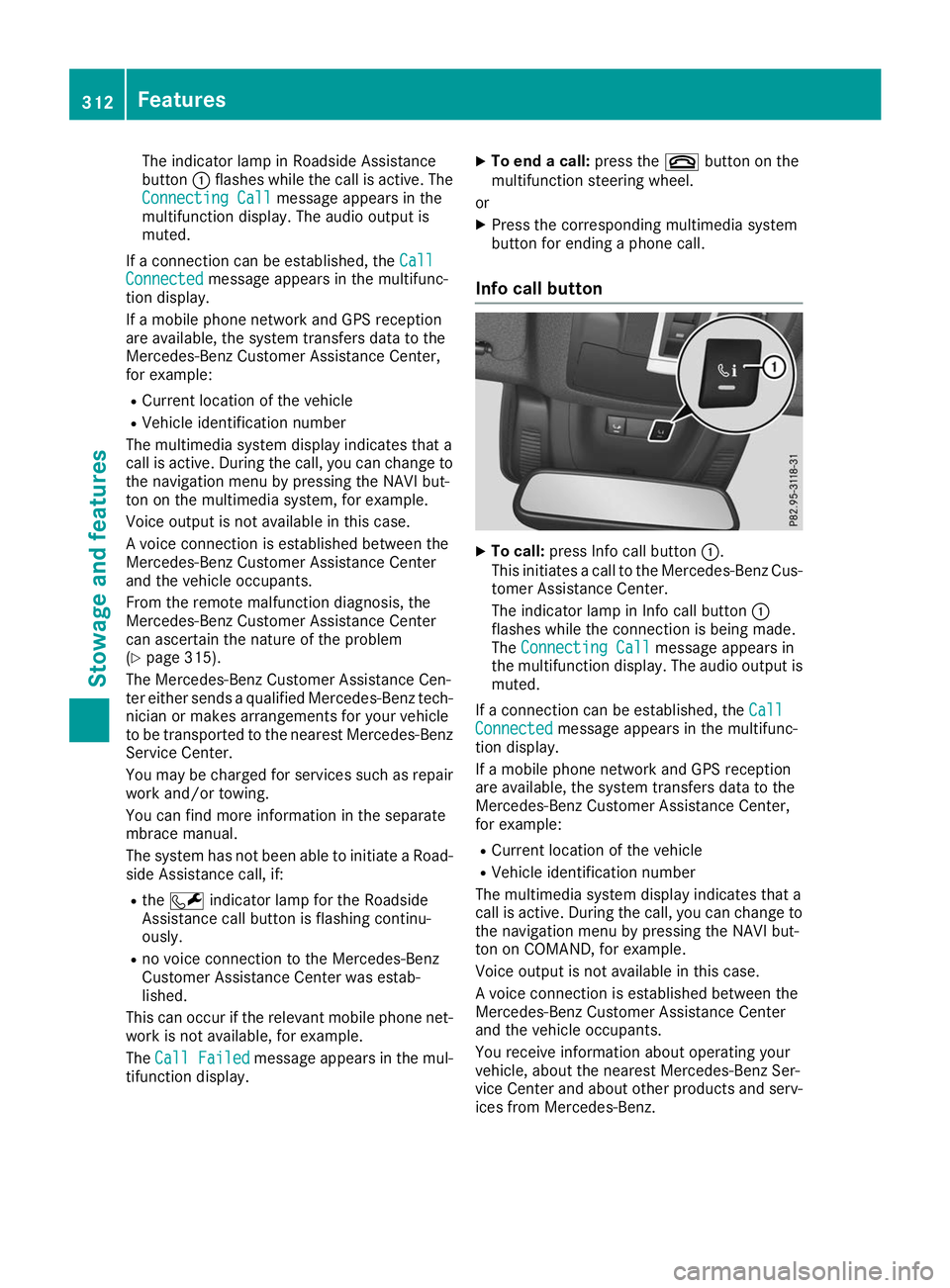
To call: press Info call button 0043.
This initiates a call to the Mercedes-Benz Cus-
tomer Assistance Center.
The indicator lamp in Info call button 0043
flashes while the connection is being made.
The Connecting Call Connecting Call message appears in
the multifunction display. The audio output is muted.
If a connection can be established, the Call
Call
Connected
Connected message appears in the multifunc-
tion display.
If a mobile phone network and GPS reception
are available, the system transfers data to the
Mercedes-Benz Customer Assistance Center,
for example:
R Current location of the vehicle
R Vehicle identification number
The multimedia system display indicates that a
call is active. During the call, you can change to
the navigation menu by pressing the NAVI but-
ton on COMAND, for example.
Voice output is not available in this case.
A voice connection is established between the
Mercedes-Benz Customer Assistance Center
and the vehicle occupants.
You receive information about operating your
vehicle, about the nearest Mercedes-Benz Ser-
vice Center and about other products and serv- ices from Mercedes-Benz. 312
FeaturesStowage and features
Page 315 of 398
You can find further information on the mbrace
system under "Owners Online" at
http://www.mbusa.com.
The system was unable to initiate an Info call if:
R the indicator lamp in the 00D9Info call button
is flashing continuously.
R no voice connection to the Mercedes-Benz
Customer Assistance Center has been estab-
lished.
This can occur if the relevant mobile phone net-
work is not available, for example.
The Call Failed
Call Failed message appears in the mul-
tifunction display.
X To end a call: press the0076button on the
multifunction steering wheel.
or X Press the corresponding multimedia system
button for ending a phone call.
Call priority When service calls are active, e.g. Roadside
Assistance or Info calls, an emergency call can
still be initiated. In this case, an emergency call
will take priority and override all other active
calls.
The indicator lamp of the respective button
flashes until the call is ended.
An emergency call can only be terminated by the
Mercedes-Benz Customer Assistance Center.
All other calls can be ended by pressing:
R the 0076 button on the multifunction steering
wheel
R the corresponding button in the multimedia
system to end the voice call
When a call is initiated, the audio system is
muted.
The mobile phone is no longer connected to the multimedia system.
However, if you want to use your mobile phone,
do so only when the vehicle is stationary and in a safe location.
Downloading destinations in COMAND Downloading destinations
Downloading destinations gives you access to a database with over 15 million points of interest
(POIs). These can be downloaded on the navi-
gation system in your vehicle. If you know the destination, the address can be downloaded.
Alternatively, you can obtain the location of
Points of Interest (POIs)/important destinations in the vicinity.
Furthermore, you can download routes with up
to four way points.
You are prompted to confirm route guidance to the address entered.
X SelectYes Yesby turning 3or sliding 1
the controller and confirm with 7.
The system calculates the route and subse-
quently starts the route guidance with the
address entered.
If you select No Nothe address can be stored in
the address book.
The destination download function is available
if: R the vehicle is equipped with a navigation sys-
tem.
R the relevant mobile phone network is availa-
ble and data transfer is possible.
Route Assistance This service is part of the mbrace PLUS Packageand cannot be purchased separately.
You can use the Route Assistance function even
if the vehicle is not equipped with a navigation
system.
Within the framework of this service, you receive a professional and reliable form of navigation
support without having to leave your vehicle.
The customer service representative finds a
suitable route depending on your vehicle's cur-
rent position and the desired destination. You
will then be guided live through the current route section.
Search and Send General notes
To use "Search & Send", your vehicle must be
equipped with mbrace and a navigation system. Additionally, an mbrace service subscription
must be completed.
"Search & Send" is a service for entering desti-
nations in the navigation system. A destination
address which is found on Google Maps ®
can be
transferred via mbrace directly to your vehicle's navigation system. Features
313Stowage and features Z
Page 319 of 398
garage door opener, contact a Mercedes-Benz
Service Center.
Alternatively, you can call the following tele-
phone assistance services:
R USA: Mercedes-Benz Customer Assistance
Center at 1-800-FOR-MERCedes
R Canada: Customer Service at
1-800-387-0100
R HomeLink ®
hotline 1-800-355-3515 (free of
charge)
More information on HomeLink ®
and/or com-
patible products is also available on the Internet
at http://www.homelink.com .
Notes on the declaration of conformity
(Y page 30).
USA: FCC ID: CB2HMIHL4
Canada: IC: 279B-HMIHL4
Important safety notes G
WARNING
When you operate or program the door with
the integrated garage door opener, persons in the range of movement of the door may
become trapped or be struck by the door.
There is a risk of injury.
When using the integrated garage door
opener, always make sure that nobody is
within the range of movement of the door. G
WARNING
Combustion engines emit poisonous exhaust
gases such as carbon monoxide. Inhaling
these exhaust gases leads to poisoning. There is a risk of fatal injury. Therefore never leave
the engine running in enclosed spaces with-
out sufficient ventilation.
Programming Programming the buttons
Pay attention to the "Important safety notes"
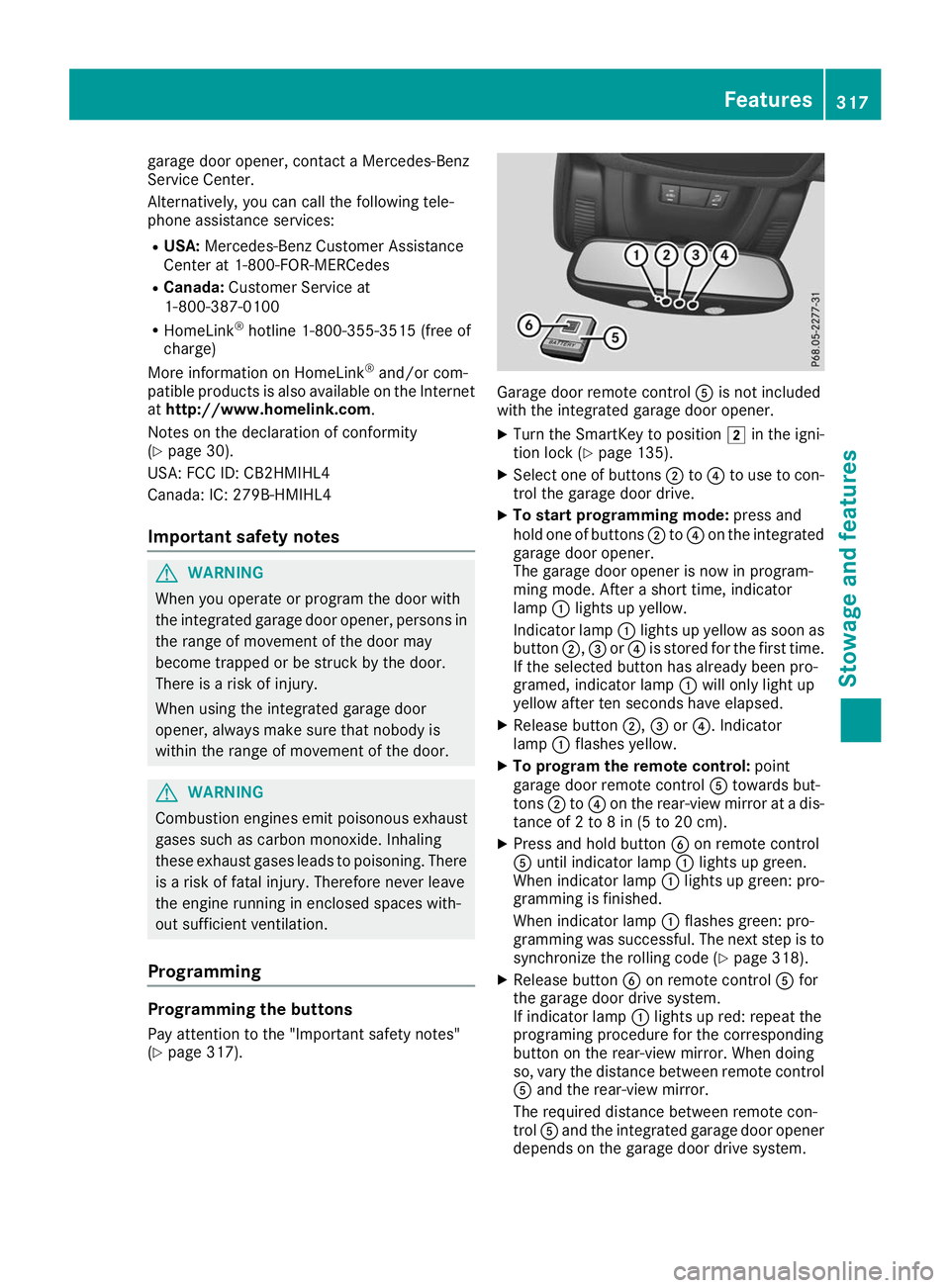
(Y page 317). Garage door remote control
0083is not included
with the integrated garage door opener.
X Turn the SmartKey to position 0048in the igni-
tion lock (Y page 135).
X Select one of buttons 0044to0085 to use to con-
trol the garage door drive.
X To start programming mode: press and
hold one of buttons 0044to0085 on the integrated
garage door opener.
The garage door opener is now in program-
ming mode. After a short time, indicator
lamp 0043lights up yellow.
Indicator lamp 0043lights up yellow as soon as
button 0044,0087or0085 is stored for the first time.
If the selected button has already been pro-
gramed, indicator lamp 0043will only light up
yellow after ten seconds have elapsed.
X Release button 0044,0087or0085. Indicator
lamp 0043flashes yellow.
X To program the remote control: point
garage door remote control 0083towards but-
tons 0044to0085 on the rear-view mirror at a dis-
tance of 2 to 8 in (5 to 20 cm).
X Press and hold button 0084on remote control
0083 until indicator lamp 0043lights up green.
When indicator lamp 0043lights up green: pro-
gramming is finished.
When indicator lamp 0043flashes green: pro-
gramming was successful. The next step is to synchronize the rolling code (Y page 318).
X Release button 0084on remote control 0083for
the garage door drive system.
If indicator lamp 0043lights up red: repeat the
programing procedure for the corresponding
button on the rear-view mirror. When doing
so, vary the distance between remote control 0083 and the rear-view mirror.
The required distance between remote con-
trol 0083and the integrated garage door opener
depends on the garage door drive system. Features
317Stowage and features Z
Page 344 of 398
occupants from suffering acid burns should the
battery be damaged in the event of an accident.
In order for the battery to achieve the maximum possible service life, it must always be suffi-
ciently charged.
Like other batteries, the vehicle battery may
discharge over time if you do not use the vehicle. In this case, have the battery disconnected at a
qualified specialist workshop. However, you can also charge the battery with a charger recom-
mended by Mercedes-Benz. Contact a qualified
specialist workshop for further information.
Have the battery charge state checked more
frequently if you use the vehicle mainly for short trips or if you leave it standing idle for a lengthyperiod. Consult a qualified specialist workshop
if you wish to leave your vehicle parked for a long
period of time.
Remove the SmartKey if you park the vehicle
and do not require any electrical consumers.
The vehicle will then use very little energy, thus
conserving battery power.
If the power supply has been interrupted, e.g. if
you reconnect the battery, you will have to:
R set the clock (see the Digital Operator's Man-
ual)
On vehicles with a multimedia system and
navigation system, the clock is set automati-
cally.
R reset the function for automatically folding
the exterior mirrors in/out by folding the mir-
rors out once(Y page 106) Charging the 12 V battery
G
WARNING
During charging and jump-starting, explosive
gases can escape from the battery. There is a risk of an explosion.
Particularly avoid fire, open flames, creating
sparks and smoking. Ensure there is sufficient
ventilation while charging and jump-starting.
Do not lean over a battery. G
WARNING
Battery acid is caustic. There is a risk of injury. Avoid contact with skin, eyes or clothing. Do
not inhale any battery gases. Do not lean over
the battery. Keep children away from batter- ies. Wash away battery acid immediately with
plenty of clean water and seek medical atten-tion. G
WARNING
A discharged battery can freeze at tempera-
tures below freezing point. When jump-start-
ing the vehicle or charging the battery, gases can escape from the battery. There is a risk of
an explosion.
Allow the frozen battery to thaw out before
charging it or jump-starting.
! Only use battery chargers with a maximum
charging voltage of 14.8 V.
! Only charge the battery using the jump-
starting connection point.
The jump-starting connection point is in the
engine compartment (Y page 343).
X Open the hood.
X Connect the battery charger to the positive
terminal and ground point in the same order
as when connecting the donor battery in the
jump-starting procedure (Y page 343).
Keep away from fire and open flames. Do not
lean over a battery. Never charge the battery if it is still installed in the vehicle, unless you use a
battery charger which has been tested and
approved by Mercedes-Benz. A battery charger
unit specially adapted for Mercedes-Benz vehi-
cles and tested and approved by Mercedes-
Benz is available as an accessory. It permits the
charging of the battery in its installed position.
Contact an authorized Mercedes-Benz Center
for further information and availability. Read the battery charger's operating instructions before
charging the battery.
If, at low temperatures, the indicator lamps/
warning lamps in the instrument cluster do not
light up, it is highly likely that the discharged
battery has frozen. In this case you may neither
jump-start the vehicle nor charge the battery.
The service life of a thawed-out battery may be
shorter. The starting characteristics can be
impaired, particularly at low temperatures. Have
the thawed-out battery checked at a qualified
specialist workshop. 342
Battery (vehicle)Breakdown assistance
Page 346 of 398
G
WARNING
A discharged battery can freeze at temperatures below freezing point. When jump-starting the
vehicle or charging the battery, gases can escape from the battery. There is a risk of an explosion.
Allow the frozen battery to thaw out before charging it or jump-starting.
! Vehicles with a gasoline engine:
avoid repeated and lengthy starting attempts. Otherwise, the
catalytic converter could be damaged by non-combusted fuel.
If the indicator/warning lamps do not light up at low temperatures, it is very likely that the dis-
charged battery has frozen. In this case you may neither jump-start the vehicle nor charge the
battery. The service life of a thawed-out battery may be shorter. The starting characteristics can be
impaired, particularly at low temperatures. Have the thawed-out battery checked at a qualified
specialist workshop.
Do not start the vehicle using a rapid charging device. If your vehicle's battery is discharged, the
engine can be jump-started from another vehicle or from a donor battery using jumper cables.
Observe the following points:
R The battery is not accessible in all vehicles. If the other vehicle's battery is not accessible, jump-
start the vehicle using a donor battery or a jump-starting device.
R Vehicles with a gasoline engine: only jump-start the vehicle when the engine and exhaust
system are cold.
R Do not start the engine if the battery is frozen. Let the battery thaw first.
R Only jump-start from batteries with a 12 V voltage rating.
R Only use jumper cables which have a sufficient cross-section and insulated terminal clamps.
R If the battery is fully discharged, leave the battery that is being used to jump-start connected for
a few minutes before attempting to start. This charges the battery slightly.
R Make sure that the two vehicles do not touch.
Make sure that:
R The jumper cables are not damaged.
R Bare parts of the terminal clamp do not come into contact with other metal parts while the jumper
cables are connected to the battery.
R The jumper cables cannot come into contact with parts that can move when the engine is running,
such as the V-belt pulley or the fan.
X Secure the vehicle by applying the electric parking brake.
X Shift the transmission to position 005D.
X Make sure that the ignition is switched off. All indicator lamps in the instrument cluster must be
off. When using the SmartKey, turn the SmartKey to position 0092in the ignition lock and remove it
(Y page 135).
X Switch off all electrical consumers, e.g. rear window defroster, lighting, etc.
X Open the hood.
i Right-hand-drive vehicle:
the jump-starting connection points may be located on the other
side of the vehicle. 344
Jump-startingBreakdown assistance