dimensions MERCEDES-BENZ GLE SUV 2019 Owners Manual
[x] Cancel search | Manufacturer: MERCEDES-BENZ, Model Year: 2019, Model line: GLE SUV, Model: MERCEDES-BENZ GLE SUV 2019Pages: 681, PDF Size: 11.7 MB
Page 276 of 681
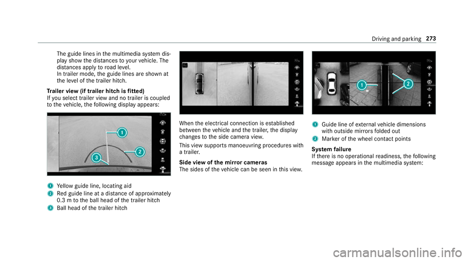
The guide lines in
the multimedia sy stem dis‐
play show the dis tances toyour vehicle. The
dis tances apply toroad le vel.
In trailer mode, the guide lines are shown at
th e le vel of the trailer hitch.
Tr ailer view (if trailer hitch is fitted)
If yo u select trailer view and no trailer is coupled
to theve hicle, thefo llowing display appears: 1
Yellow guide line, locating aid
2 Red guide line at a dis tance of appr oximately
0.3 m tothe ball head of the trailer hitch
3 Ball head of the trailer hitch When
the electrical connection is es tablished
between theve hicle and the trailer, the display
ch anges tothe side camera vie w.
This view supports manoeuvring procedures with
a trailer.
Side view of the mir ror cameras
The sides of theve hicle can be seen in this vie w. 1
Guide line of extern al vehicle dimensions
with outside mir rors folded out
2 Marker of the wheel conta ct points
Sy stem failure
If th ere is no operational readiness, thefo llowing
message appears in the multimedia sy stem: Driving and parking
273
Page 538 of 681
Af
teryo u ha vedriven for a few minutes, the
tyre pressu reloss warning sy stem monitors
th e set tyre pressures of all the tyres.
Be sure toalso obse rveth efo llowing fur ther
re lated subjects:
R Notes on tyre pressure (→ page 526)Wheel
change Note
s on selecting, fitting and replacing
tyres Yo
u can ask for information rega rding permit ted
wheel/tyre combinations at a Mercedes-Benz
Service Cent re. &
WARNING Risk of accident due toincor‐
re ct dimensions of wheels and tyres
If wheels and tyres of the wrong size are
used, the wheel brakes or wheel suspension
components may become damaged. #
Alw aysre place wheels and tyres with
th ose that fulfil the specifications of the
original part. When
replacing wheels, make sure tofit the
cor rect:
R Designation
R Type
When replacing tyres, make sure tofit the
cor rect:
R Designation
R Manufactu rer
R Type &
WARNING Risk of inju rythro ugh exceed‐
ing the specified tyre load-bearing capa‐
city or the permissible speed rating
Exceeding the specified tyre load-bearing
capacity or the permissible speed rating may
lead totyre dama geand tothe tyres bur st‐
ing. #
Therefore, only use tyre types and sizes
appr ovedfo ryo ur vehicle model. #
Obser vethe tyre load-bearing capacity
ra ting and speed rating requ iredfor
yo ur vehicle. *
NO
TEVehicle and tyre damage thro ugh
tyre types and sizes that ha venot been
appr oved Fo
r saf etyre asons, on lyuse tyres, wheels
and accessories which ha vebeen specially
appr ovedby Mercedes-Benz foryo ur vehicle.
These tyres are specially adap tedto the con‐
trol sy stems, such as ABS, ESP ®
and
4MATIC, and mar ked as follo ws:
R MO = Mercedes-Benz Original
R MOE = Mercedes-Benz Original Extended
(run-flat tyres only for cer tain wheels)
R MO1 = Mercedes-Benz Original (only cer‐
tain AMG tyres)
Cer tain characteristics, such as handling,
ve hicle noise emissions, fuel consum ption,
et c. may otherwise be adversely af fected.
Fu rthermore, other tyre sizes could result in Wheels and tyres
535
Page 541 of 681
Note
s on inter changing wheels &
WARNING Risk of inju rythro ugh dif fer‐
ent wheel sizes
Inter changing the front and rear wheels if the
wheels or tyres ha vediffere nt dimensions
may se verely impair the driving characteris‐
tics.
The disk brakes or wheel suspension compo‐
nents may also be damaged. #
Rotate front and rear wheels on lyifthe
wheels and tyres are of the same
dimensions. Inter
changing the front and rear wheels if the
wheels or tyres ha vediffere nt dimensions can
re nder thege neral operating pe rmit in valid.
The wear pat tern s on the front and rear wheels
dif fer:
R Front wheels wear more on the shoulder of
th e tyre
R Rear wheels wear more in the cent reofthe
tyre On
vehicles with the same front and rear wheel
size, you can inter change the wheels every
5,000 to10,000 km, depending on thewe ar.
Ensure the direction of rotation is maintained for
th e wheels.
It is imperative toobser vethe instructions and
saf ety no tes on "Wheel change" when doing so. Note
s onstoring wheels R
Afterre moving wheels, store them in a cool,
dry and preferably dark place.
R Protect the tyres from conta ct withoil,
grease or fuel. Overview of
the ty re-change tool kit Apart from some countr
y-specific variants, vehi‐
cles are not equipped with a tyre-change tool kit.
Fo r more information on which tools are
requ ired and appr ovedto per form a wheel
ch ange on your vehicle, consult a qualified spe‐
cialist workshop. Re
quired tyre-change tool kits may include, for
ex ample:
R jack
R chock
R wheel wrench
R centri ng pin
% The jack weighs appr oximately 3.4 kg.
The maximum load capacity of the jack can
be found on thest icke r af fixe dto the jac k.
The jack is maintenance-free. If there is a
malfunction, please conta ct aqualified spe‐
cialist workshop.
The tyre-change tool kit is located under the load
compartment floor. 538
Wheels and tyres
Page 547 of 681
#
Check the tyre pressure of the newly moun‐
te d wheel and adjust according ly.#
Vehicles with tyre pressure loss warning
sy stem: restart the tyre pressure loss warn‐
ing sy stem (→ page 534).
Exception: the new wheel is an emer gency
spa rewheel. #
Vehicles with a tyre pressure monitoring
sy stem: restart the tyre pressure monitoring
sy stem (→ page 529).
Exception: the new wheel is an emer gency
spa rewheel. Emer
gency spare wheel Note
s onthe emer gency spare wheel &
WARNING Risk of accident caused by
incor rect wheel and tyre dimensions
The wheel or tyre size and the tyre type of
th e emer gency spa rewheel or spare wheel
and the wheel tobe replaced may dif fer.
Mounting an emer gency spa rewheel/spare wheel may se
verely impair the driving char‐
acteristics.
To preve nt hazardous situations: #
Adapt your driving style according lyand
drive carefull y. #
Neverfit more than one emer gency
spa rewheel or spare wheel that dif fers
in size. #
Only use an emer gency spa rewheel or
spare wheel of a dif fere nt size brie fly. #
Do not switch off ESP ®
. #
Have the emer gency spa rewheel or
spare wheel of a dif fere nt size replaced
at the nearest qualified specialist work‐
shop. The new wheel must ha vethe
cor rect dimensions. Check
the tyre pressure of the emer gency spa re
wheel fitted. Co rrect the pressure as necessar y.
The maximum permissible speed with an emer‐
ge ncy spa rewheel fitted is 80 km/h.
Do not fit th e emer gency spa rewheel with sn ow
ch ains. Re
place the emer gency spa rewheel af ter six
ye ars at the latest, rega rdless of wear.
% Ve
hicles with a tyre pressure loss warn‐
ing sy stem: If an emer gency spa rewheel is
fi tted the tyre pressure loss warning sy stem
cann otfunction reliabl y.Only restart the sys‐
te m again when the emer gency spa rewheel
has been replaced with a new wheel.
Ve hicles with a tyre pressure monitoring
sy stem: If an emer gency spa rewheel is fit‐
te dth e tyre pressure monitoring sy stem can‐
not function reliabl y.Only restart the sy stem
again when the emer gency spa rewheel has
been replaced with a new wheel.
Ve hicles with a tyre pressure monitoring
sy stem: For a few minutes af ter an emer‐
ge ncy spa rewheel is fitted, the sy stem may
st ill display the tyre pressure of there mo ved
wheel.
Be sure toalso obse rveth efo llowing fur ther
re lated subjects:
R Notes on tyre pressure (→ page 526)
R Tyre pressure table (→ page 527) 544
Wheels and tyres
Page 548 of 681
Re
moving the eme rgency spa rewheel The eme
rgency spare wheel is located under the
load compartment floor. #
Obser vethe information on mounting tyres
(→ page 535). #
Open theta ilgate. #
Open the load compartment floor
(→ page 136). #
Remo vethe emer gency spa rewheel bag with
th e emer gency spa rewheel. #
Open the emer gency spa rewheel bag and
re mo vethe emer gency spa rewheel. Collapsible spa
rewheel Note
s onthe collapsible spa rewheel &
WARNING Risk of accident caused by
incor rect wheel and tyre dimensions
The wheel or tyre size and the tyre type of
th e emer gency spa rewheel or spare wheel
and the wheel tobe replaced may dif fer. Mounting an emer
gency spa rewheel/spare
wheel may se verely impair the driving char‐
acteristics.
To preve nt hazardous situations: #
Adapt your driving style according lyand
drive carefull y. #
Neverfit more than one emer gency
spa rewheel or spare wheel that dif fers
in size. #
Only use an emer gency spa rewheel or
spare wheel of a dif fere nt size brie fly. #
Do not switch off ESP ®
. #
Have the emer gency spa rewheel or
spare wheel of a dif fere nt size replaced
at the nearest qualified specialist work‐
shop. The new wheel must ha vethe
cor rect dimensions. The collapsible spa
rewheel is an emer gency
wheel which is only suitable for use for a limi ted
period of time and in a restricted manner in the
eve nt of a flat tyre (e.g. until the nearest work‐
shop). The tyre side
walls are folded when in transpo rt
mode. Before use, the collapsible spare wheel
has tobe inflated with the accompanying com‐
pressor.
Check the tyre pressure of the collapsible spare
wheel once fitted. Co rrect the pressure as nec‐
essar y.
The maximum permissible speed with a collapsi‐
ble spare wheel fitted is 80 km/h.
Do not fit snow chains with the collapsible spare
wheel.
Re place the collapsible spare wheel af ter six
ye ars at the latest, rega rdless of wear.
% Ve
hicles with a tyre pressure loss warn‐
ing sy stem: if a collapsible spare wheel is
fi tted, the tyre pressure loss warning sy stem
cann otfunction reliabl y.Only restart the sys‐
te m again when the collapsible spare wheel
has been replaced with a new wheel. Wheels and tyres
545
Page 563 of 681
Ve
hicle data Ve
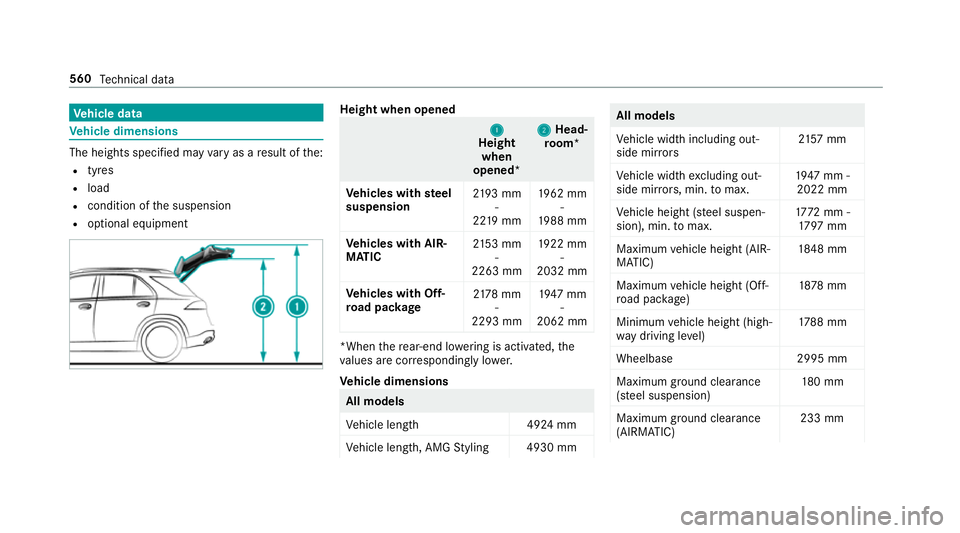
hicle dimensions The heights speci
fied may vary as a result of the:
R tyres
R load
R condition of the suspension
R optional equipment Height when opened
1 1
Height
when
opened* 2 2
Head‐
ro om*
Ve hicles with steel
suspension 21
93 mm
-
22 19 mm 19
62 mm
-
19 88 mm
Ve hicles with AIR‐
MATIC 21
53 mm
-
2263 mm 19
22 mm
-
2032 mm
Ve hicles with Off-
ro ad pac kage 21
78 mm
-
2293 mm 19
47 mm
-
2062 mm *When
there ar-end lo wering is acti vated, the
va lues are cor respondingly lo wer.
Ve hicle dimensions All models
Ve
hicle lengt h4 924 mm
Ve hicle length, AMG Styling 4930 mm All models
Ve
hicle width including out‐
side mir rors 21
57 mm
Ve hicle width excluding out‐
side mir rors, min. tomax. 19
47 mm -
2022 mm
Ve hicle height (s teel suspen‐
sion), min. tomax. 17
72 mm -
17 97 mm
Maximum vehicle height (AIR‐
MATIC) 18
48 mm
Maximum vehicle height (Off-
ro ad pac kage) 18
78 mm
Minimum vehicle height (high‐
wa y driving le vel) 17
88 mm
Wheelbase 2995 mm
Maximum ground clea rance
(s te el suspension) 18
0 mm
Maximum ground clea rance
(AIRMATIC) 233 mm560
Tech nical da ta
Page 567 of 681
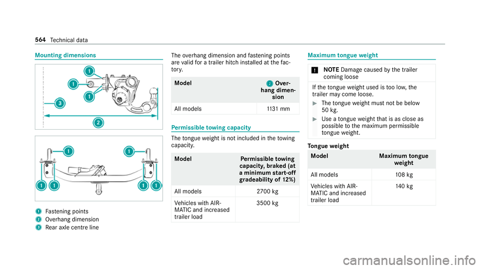
Mounting dimensions
1
Fastening points
2 Overhang dimension
3 Rear axle centre line The
overhang dimension and fastening points
are valid for a trailer hitch ins talled at thefa c‐
to ry. Model
2 2Over‐
hang dimen‐ sion
All model s1 131 mm Pe
rm issible towing capacity The
tongue weight is not included in theto wing
capacity. Model
Perm issible towing
capacit y,braked (at
a minimum start-off
gr adeability of 12%)
All models 2700 kg
Ve hicles with AIR‐
MATIC and increased
trailer load 3500
kg Maximum
tongue weight *
NO
TEDama gecaused bythe trailer
coming loose If
th eto ngue weight used is too lo w,the
trailer may come loose. #
The tongue weight must not be below
50 kg. #
Use a tongue weight that is as close as
possible tothe maximum permissible
to ngue weight. To
ngue weight Model
Maximumtongue
we ight
All models 108kg
Ve hicles with AIR‐
MATIC and increased
trailer load 14
0kg 564
Tech nical da ta
Page 668 of 681
Suspension
Free driving mode (ACTIVE BODY
CO NTROL) ........................................... 258
Individual wheel control (ACTIVE
BO DY CONTROL) .................................2 59
Setting the suspension le vel (ACTIVE
BO DY CONTROL) .................................2 59
Setting the suspension le vel (AIR‐
MATIC) ................................................ 250
Suspension see ACTIVE BODY CONTROL
see AIR BODY CONTROL
Suspension le vel (ACTIVE BODY CON‐
TROL)
Setting ................................................ .259
Suspension le vel (AIRMATIC)
Setting ................................................ .250
SV HC (substances of very high con‐
cern ).......................................................... .29
Switch-off delay time Exterior ................................................ 15 3
Interior ................................................ 15 5
Switching on voice amplification
Multimedia sy stem .............................. 368 Synchronisation function
Activating/deactivating (multimedia
sy stem) ................................................ 16 8
Switching on/off (control panel) ......... 16 8
Sy stem settings
Ac tivating/deactivating PIN pr otec‐
tion ...................................................... 373
Re set function (multimedia sy stem) ....3 75
Setting the dis tance unit ..................... 372
Setting the time and date automati‐
cally ..................................................... 367
Setting the time zone .......................... 367
Setting the time/date form at .............. 367
Swit ching transmission of theve hicle
position on/off .................................... 368
Sy stem settings
see Blue tooth®
see Data import/export
see Language
see Software update
see Wi-Fi T
Ta ilgate ...................................................... .86
Closing .................................................. 87HANDS-FREE
ACCESS .......................... .88
Limiting the opening angle .................... 90
Opening .................................................86
Opening dimensions ............................5 60
Un locking (emer gency key) .................. .90
Ta ilgate
see Locking/unlocking
Ta ke -back of end-of-life vehicles .............. 22
Pr otection of the environment ............... 22
Ta nk capacity
Fu el ..................................................... 555
Re ser ve(fuel) ...................................... 555
Ta nk content
Ad Blue ®
............................................... 556
Te ch nical data
Axle load (trailer operation) ................. 565
Fa stening points (trailer hitch) .............5 64
Information .......................................... 548
Mounting dimensions (trailer hitch) ..... 564
No tes (trailer hitch) ............................. 563
Overhang dimension (trailer hitch) ...... 564
To ngue weight .................................... .564
To wing capacity (trailer operation) ...... 564
Ty re pressure monitoring sy stem ........ 530 Index
665
Page 671 of 681
Extending/r
etra cting the ball neck ...... 292
Fa stening points ..................................5 64
Gene ral no tes ...................................... 563
Mounting dimensions .......................... 564
No tes ................................................... 291
Overhang dimension ........................... 564
Soc ket ................................................. 294
To ngue weight .................................... .564
To wing capacity .................................. .564
Tr ailer Manoeuv ring Assi st.................. 265
Tr ailer Manoeuvring Assist ..................... 265
Ad justing the articulation angle ........... 267
Fu nction .............................................. 265
St raightening manoeuvre .................... 267
Using .................................................. .266
Tr ailer operation
Bicycle rack ......................................... 296
Coupling up/uncoupling a trailer ........ 294
Extending/r etra cting the ball neck ...... 292
No tes ................................................... 291
Soc ket ................................................. 294
Tr ailer stabilisation
Fu nction/no tes ................................... 220 Tr
ailer tow hit ch
Care .................................................... 499
Tr ansfer case
HIGH RANGE ....................................... 197
LO W RANGE ......................................... 197
Shifting ................................................ 19 8
Tr ansfer redve hicle data
Android Auto ....................................... 444
Apple CarPl ay™ ................................... 444
Baidu CarLife ....................................... 444
Tr ansmission position display ................19 3
Tr anspo rting
Ve hicle ................................................ 520
Tr im elements (Care) ...............................501
Tr ip
Menu (on-board computer) .................. 306
Tr ip computer
Displaying ............................................ 306
Re setting ............................................. 307
Tr ip distance ............................................ 306
Displaying ............................................ 306
Re setting ............................................. 307 Tr
ip me ter
see Trip dis tance
Tu rn signal indicator
see Turn signal lights
Tu rn signal lights .....................................1 49
Switching on/off ................................. 14 9
TV ............................................................. 323
Ac tivating ............................................ .476
Ad justing the brightness ..................... 482
Calling up the menu (CI+ module) .......4 83
Information .......................................... 475
Overview ............................................. 477
Picture settings ................................... 482
Setting subtitles ..................................4 81
Setting the audio language .................. 481
Showing telete xt ................................. .482
Showing/hiding full screen .................. 478
Te lete xt overview ................................. 481
Vo ice commands (LINGU ATRO NIC) .....3 23
TV channel
Ac tivating/deactivating channel fix ..... 479
Channel fix .......................................... 479
Channel list overview .......................... 480
EPG (elect ronic programme guide) ...... 479668
Index
Page 673 of 681
Un
usual handling characteristics ........ 525 U
Un its of measurement
Setting ................................................ .372
Un locking setting ...................................... 78
USB port ...................................................1 43
User profile .............................................. 344 V
Ve hicle ...................................................... 180
Ac tivating/deactivating standby
mode .................................................. .214
Ad ditional door lock ...............................81
Cor rect use ........................................... 29
Dama gedetection (pa rking) ................ .212
Data acquisition .................................... 30
Data storage .......................................... 30
Diagnostics connection .........................27
Equipment ............................................. 24
Implied warranty .................................. .29
Locking (auto matically) ......................... 85
Locking (digital vehicle keyst icke r) ...... .82
Locking (from the inside) ....................... 82 Locking (KEYLESS-GO) .......................... 83
Locking (mobile phone) .........................82
Locking/unlocking (emergency
key) .... .85
Lo we ring ............................................. 543
Pa rking up ............................................ 213
QR code rescue card ............................. 29
Qualifi ed specialist workshop ................28
Ra ising ................................................ 539
REA CHregulation ..................................29
Re gistration ...........................................28
St andby mode function ........................ 213
St arting (Digital Vehicle Keyst icke r) .... 17 9
St arting (eme rgency operation
mode) .................................................. 180
St arting (mobile phone) ...................... .179
St arting (s tart/s top button) .................1 79
Switching off (s tart/s top button) ........ 205
To wing ................................................ .298
Un locking (digital vehicle keyst icke r) .... 82
Un locking (from the inside) ...................82
Un locking (KEYLESS-GO) ...................... .83
Un locking (mobile phone) ...................... 82
Ve ntilating (co nvenience opening) ......... 93
Vo ice commands (LINGU ATRO NIC) .....3 29Ve
hicle data
Angle of app roach/departure .............. 561
Displaying (DYNAMIC SELECT) ............ 19 2
Fo rding dep th...................................... 561
Maximum gradient climbing ability ...... 561
Ro of load ............................................. 561
Tr ans ferring toAndroid Auto™ ............ 444
Tr ans ferring toApple CarPl ay™ ........... 444
Tr ans ferring toBaidu CarLife™ ............ 444
Ve hicle height ...................................... 560
Ve hicle length ...................................... 560
Ve hicle width ....................................... 560
Wheelbase ...........................................5 60
Ve hicle dimensions ................................. 560
Ve hicle identification number
see VIN
Ve hicle identification plate
EU general operating pe rmit number .. 550
Pa int code .......................................... .550
Pe rm issible axle load .......................... .550
Pe rm issible gross mass ...................... .550
VIN ...................................................... 550
Ve hicle identification plate
see Model series 67 0
Index