ECO mode MERCEDES-BENZ GLK-Class 2015 X204 User Guide
[x] Cancel search | Manufacturer: MERCEDES-BENZ, Model Year: 2015, Model line: GLK-Class, Model: MERCEDES-BENZ GLK-Class 2015 X204Pages: 386, PDF Size: 7.16 MB
Page 175 of 386
additional warning messages in the multi-
function display.
The brake fluid level may be too low due to brake pad wear or leaking brake lines.
Have the brake system checked immedi-
ately. This work should be carried out at a
qualified specialist workshop.
All checks and maintenance work on the
brake system must be carried out at a quali-
fied specialist workshop. Consult a qualified
specialist workshop to arrange this.
Have brake pads installed and brake fluid
replaced at a qualified specialist workshop.
! Vehicles with 4MATIC:
function or per-
formance tests may only be carried out on
a 2-axle dynamometer. If you are planning
to have the vehicle tested on such a dyna-
mometer, contact an authorized Mercedes- Benz Center to obtain further information
first. Otherwise, you could damage the
drive train or the brake system.
! As the ESP ®
system operates automati-
cally, the engine and the ignition must be
switched off (SmartKey in position 0or 1in
the ignition lock) when:
R testing the parking brake on a brake
dynamometer.
R you intend to have the vehicle towed with
the front or rear axle raised (not permit-
ted for vehicles with 4MATIC).
Braking maneuvers triggered automatically
by ESP ®
may seriously damage the brake
system.
If the brake system has only been subject to
moderate loads, you should test the function-
ality of your brakes at regular intervals. To do so, press firmly on the brake pedal when driv-
ing at a high speed. This improves the grip of
the brake pads.
You can find a description of Brake Assist
(BAS) on (Y page 69).
Mercedes-Benz recommends that you only
have brake pads/linings installed on your
vehicle which have been approved for Mercedes-Benz vehicles or which correspond
to an equivalent quality standard. Brake
pads/linings which have not been approved
for Mercedes-Benz vehicles or which are not
of an equivalent quality could affect your vehi- cle's operating safety.
Mercedes-Benz recommends that you only
use brake fluid that has been specially
approved for your vehicle by Mercedes-Benz,
or which corresponds to an equivalent quality standard. Brake fluid which has not been
approved for Mercedes-Benz vehicles or
which is not of an equivalent quality could
affect your vehicle's operating safety.
Parking brake G
WARNING
If you must brake the vehicle with the parking brake, the braking distance is considerably
longer and the wheels could lock. There is an
increased danger of skidding and accidents.
Only use the parking brake to brake the vehi- cle when the service brake is faulty. Do not
apply the parking brake too firmly. If the
wheels lock, release the parking brake until
the wheels begin turning again.
If you brake the vehicle with the parking
brake, the brake lamps will not light up.
If you drive on wet roads or dirt-covered sur-
faces, road salt and/or dirt could get into the parking brake.
In order to prevent corrosion and a reduction
in the braking power of the parking brake,
observe the following:
R gently depress the parking brake from time
to time before beginning the journey.
R Drive for approximately 110 yds (100 m) at
a maximum speed of 12 mph (20 km/h). Driving tips
173Driving and parking Z
Page 204 of 386
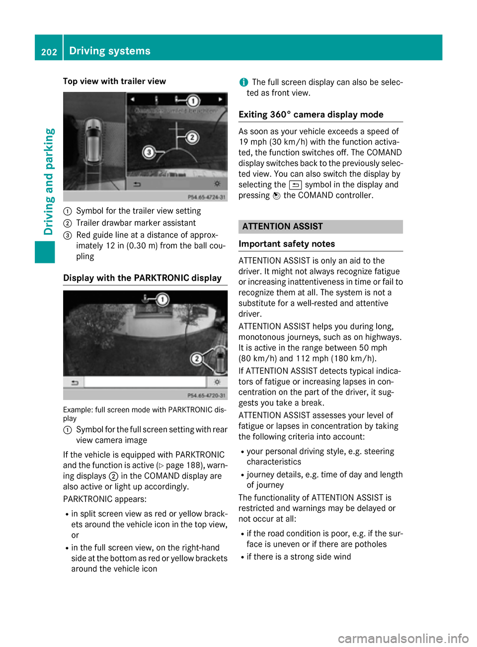
Top view with trailer view
0043
Symbol for the trailer view setting
0044 Trailer drawbar marker assistant
0087 Red guide line at a distance of approx-
imately 12 in (0.30 m) fromthe ball cou-
pling
Display with the PARKTRONIC display Example: full screen mode with PARKTRONIC dis-
play
0043 Symbol for the full screen setting with rear
view camera image
If the vehicle is equipped with PARKTRONIC
and the function is active (Y page 188), warn-
ing displays 0044in the COMAND display are
also active or light up accordingly.
PARKTRONIC appears:
R in split screen view as red or yellow brack-
ets around the vehicle icon in the top view, or
R in the full screen view, on the right-hand
side at the bottom as red or yellow brackets
around the vehicle icon i
The full screen display can also be selec-
ted as front view.
Exiting 360° camera display mode As soon as your vehicle exceeds a speed of
19 mph (30 km/h) with the function activa-
ted, the function switches off. The COMAND
display switches back to the previously selec-
ted view. You can also switch the display by
selecting the 0039symbol in the display and
pressing 0098the COMAND controller. ATTENTION ASSIST
Important safety notes ATTENTION ASSIST is only an aid to the
driver. It might not always recognize fatigue
or increasing inattentiveness in time or fail to
recognize them at all. The system is not a
substitute for a well-rested and attentive
driver.
ATTENTION ASSIST helps you during long,
monotonous journeys, such as on highways.
It is active in the range between 50 mph
(80 km/h) and 112 mph (180 km/h).
If ATTENTION ASSIST detects typical indica-
tors of fatigue or increasing lapses in con-
centration on the part of the driver, it sug-
gests you take a break.
ATTENTION ASSIST assesses your level of
fatigue or lapses in concentration by taking
the following criteria into account:
R your personal driving style, e.g. steering
characteristics
R journey details, e.g. time of day and length
of journey
The functionality of ATTENTION ASSIST is
restricted and warnings may be delayed or
not occur at all:
R if the road condition is poor, e.g. if the sur-
face is uneven or if there are potholes
R if there is a strong side wind 202
Driving systemsDriving an
d parking
Page 218 of 386
R
When you couple up a trailer, check at reg-
ular intervals that the load is firmly secured.If the trailer is equipped with trailer lights
and brakes, check the trailer to ensure that
these are working.
R Bear in mind that the handling will be less
stable when towing a trailer than when driv-
ing without one. Avoid sudden steering
movements.
R The vehicle/trailer combination is heavier,
accelerates more slowly, has a decreased
gradient climbing capability and a longer
braking distance.
It is more susceptible to side winds and
requires more careful steering.
R If possible, avoid abrupt braking. Depress
the brake pedal moderately at first, so that the trailer can activate its own brakes. Thenincrease the pressure on the brake pedal.
R If the automatic transmission repeatedly
shifts between gears on uphill or downhill
gradients, shift to a lower gear using the
left-hand steering wheel paddle shifter.
A lower gear and lower speed reduce the
risk of engine failure.
R When driving downhill, shift to a lower gear
to utilize the engine's braking effect.
Avoid continuous brake application as this
may overheat the vehicle brakes and, if
installed, the trailer brakes.
R If the coolant temperature increases dra-
matically while the air-conditioning system
is switched on, switch off the air-condition-
ing system.
Coolant heat can additionally be dissipated
by opening the windows and by setting the
blower fan and the interior temperature to
maximum.
R When overtaking, pay particular attention
to the extended length of your vehicle/
trailer combination.
Due to the length of the vehicle/trailer
combination, you require additional road
space in relation to the vehicle you are
overtaking, before you can change back to
the original lane. Decoupling a trailer
G
WARNING
If you uncouple a trailer with the overrun
brake engaged, you could trap your hand
between the vehicle and the trailer drawbar.
There is a risk of injury.
Do not uncouple a trailer if the overrun brake is engaged.
! Do not disconnect a trailer with an
engaged overrun brake. Otherwise, your
vehicle could be damaged by the rebound- ing of the overrun brake.
X Make sure that the automatic transmission
is set to position P.
X Apply the vehicle's parking brake.
X Close all doors and the tailgate.
X Apply the trailer's parking brake.
X Remove the trailer cable and decouple the
trailer. Permissible trailer loads and drawbar
loads
Weight specifications The gross trailer weight is calculated by add-
ing the weight of the trailer to the weight of
the load and equipment on the trailer.
You will find installing dimensions and loads
under "Technical data" (Y
page 381).
Loading a trailer R
When loading the trailer, make sure that
neither the permissible gross weight of the
trailer nor the gross vehicle weight is
exceeded. The permissible gross vehicle
weight is indicated on the identification
plate on the B-pillar on the driver's side of
the vehicle.
You can find the maximum permissible val-
ues on the type plates of your vehicle and
the trailer. When calculating how much
weight the vehicle and trailer may carry, 216
Towing a trailerDriving and parking
Page 222 of 386
Useful information
i This Operator's Manual describes all
models and all standard and optional equip- ment of your vehicle available at the time of
publication of the Operator's Manual.
Country-specific differences are possible.
Please note that your vehicle may not be
equipped with all features described. This
also applies to safety-related systems and
functions.
i Read the information on qualified special-
ist workshops (Y page 27). Important safety notes
G
WARNING
If you operate information systems and com-
munication equipment integrated in the vehi- cle while driving, you will be distracted from
traffic conditions. You could also lose control of the vehicle. There is a risk of an accident.
Only operate the equipment when the traffic
situation permits. If you are not sure that this
is possible, park the vehicle paying attention
to traffic conditions and operate the equip-
ment when the vehicle is stationary.
You must observe the legal requirements for
the country in which you are currently driving when operating the on-board computer. G
WARNING
If the instrument cluster has failed or mal-
functioned, you may not recognize function
restrictions in systems relevant to safety. The operating safety of your vehicle may be
impaired. There is a risk of an accident.
Drive on carefully. Have the vehicle checked
at a qualified specialist workshop immedi-
ately.
The on-board computer only shows messages
or warnings from certain systems in the mul- tifunction display. You should therefore make
sure your vehicle is operating safely at all times. Otherwise, a vehicle that is not oper-
ating safely may cause an accident.
If the operating safety of your vehicle is
impaired, park the vehicle safely as soon as
possible. Contact a qualified specialist work-
shop.
For an overview, see the instrument panel
illustration (Y
page 33). Displays and operation
Coolant temperature display
G
WARNING
Opening the hood when the engine is over-
heated or when there is a fire in the engine
compartment could expose you to hot gases
or other service products. There is a risk of
injury.
Let an overheated engine cool down before
opening the hood. If there is a fire in the
engine compartment, keep the hood closed
and contact the fire department.
The coolant temperature gauge is in the
instrument cluster on the left-hand side.
Under normal operating conditions and with
the specified coolant level, the coolant tem-
perature may rise to 248 ‡ (120 †).
! A display message is shown if the coolant
temperature is too high.
If the coolant temperature is over 248 ‡
(120 †), do not continue driving. The
engine will otherwise be damaged. Tachometer
The red band in the tachometer indicates the
engine's overrevving range.
! Do not drive in the overrevving range, as
this could damage the engine.
The fuel supply is interrupted to protect the
engine when the red band is reached. 220
Displays and operationOn-board computer and displays
Page 234 of 386
around the vehicle are displayed in orange
in the multifunction display.
X Press the 0076button to save the setting.
Deactivating delayed switch-off of the exte-
rior lighting temporarily:
X Before leaving the vehicle, turn the Smart-
Key to position 0in the ignition lock.
X Turn the SmartKey to position 2in the igni-
tion lock.
The exterior lighting delayed switch-off is
deactivated.
Delayed switch-off of the exterior lighting is
reactivated the next time you start the
engine.
If you have activated the Surround Light‐
Surround Light‐
ing
ing function and the light switch is set to
0058, the following functions are activated
when it is dark:
R surround lighting: the exterior lighting
remains lit for 40 seconds after unlocking
with the SmartKey. If you start the engine,
the surround lighting is switched off and
automatic headlamp mode is activated
(Y page 117).
R exterior lighting delayed switch-off: the
exterior lighting remains lit for 60 seconds
after the engine is switched off. If you close all the doors and the tailgate, the exterior
lighting goes off after 5 seconds.
i Depending on your vehicle's equipment,
when the surround lighting and delayed
switch-off exterior lighting are on, the fol-
lowing light up:
R Parking lamps
R Front fog lamps
R Low-beam headlamps
R Daytime running lamps
R Side marker lamps
R Surround lighting in the exterior mirrors
Activating/deactivating the interior light-
ing delayed switch-off
If you activate the Interior Lighting
Interior Lighting
Delay
Delay function, the interior lighting remains on for 20 seconds after you remove the
SmartKey from the ignition lock.
X Press the 0059or0065 button on the steer-
ing wheel to select the Sett Settmenu.
X Press the 0064or0063 button to select the
Lights
Lights submenu.
X Press 0076to confirm.
X Press the 0064or0063 button to select the
Interior Lighting Delay
Interior Lighting Delay function.
If the Interior
Interior Lighting
Lighting Delay
Delayfunction
has been switched on, the vehicle interior is
displayed in orange in the multifunction
display.
X Press the 0076button to save the setting.
Vehicle Activating/deactivating the automatic
door locking mechanism
X Press the 0059or0065 button on the steer-
ing wheel to select the Sett. Sett.menu.
X Press the 0064or0063 button to select the
Vehicle
Vehicle submenu.
X Press 0076to confirm.
X Press the 0064or0063 button to select the
Auto. Door Locks
Auto. Door Locks function.
When the Auto. Door Locks
Auto. Door Locks function is
activated, the vehicle doors are displayed
in orange in the multifunction display.
X Press the 0076button to save the setting.
If you activate the Auto. Door Locks Auto. Door Locks func-
tion, the vehicle is centrally locked above a
speed of around 9 mph (15 km/h).
For further information on the automatic lock-
ing feature, see (Y page 85).
Activating/deactivating the acoustic
locking verification signal
If you switch on the Acoustic AcousticLock
Lockfunction,
an acoustic signal sounds when you lock the
vehicle.
X Press the 0059or0065 button on the steer-
ing wheel to select the Sett. Sett.menu.
X Press the 0064or0063 button to select the
Vehicle Vehicle submenu. 232
Menus and submenusOn-board computer and displays
Page 276 of 386
Useful information
i This Operator's Manual describes all
models and all standard and optional equip- ment of your vehicle available at the time of
publication of the Operator's Manual.
Country-specific differences are possible.
Please note that your vehicle may not be
equipped with all features described. This
also applies to safety-related systems and
functions.
i Read the information on qualified special-
ist workshops (Y page 27). Loading guidelines
G
WARNING
If objects, luggage or loads are not secured or not secured sufficiently, they could slip, tip
over or be flung around and thereby hit vehicle
occupants. There is a risk of injury, particu-
larly in the event of sudden braking or a sud-
den change in direction.
Always store objects so that they cannot be
flung around. Secure objects, luggage or
loads against slipping or tipping before the
journey. G
WARNING
Combustion engines emit poisonous exhaust
gases such as carbon monoxide. If the tailgate is open when the engine is running, particu-
larly if the vehicle is moving, exhaust fumes
could enter the passenger compartment.
There is a risk of poisoning.
Turn off the engine before opening the tail-
gate. Never drive with the tailgate open. G
WARNING
The exhaust tail pipe and tail pipe trim can
become very hot. If you come into contact
with these parts of the vehicle, you could burn
yourself. There is a risk of injury.
Always be particularly careful around the
exhaust tail pipe and the tail pipe trim. Allow these components to cool down before touch-
ing them.
The gross vehicle weight (GVW) is the vehicle
weight including fuel, vehicle tool kit, spare
wheel, installed accessories, vehicle occu-
pants and luggage/cargo.
The gross load limit and the gross vehicle
weight rating (GVWR) for your vehicle must
never be exceeded. The gross load limit and
the GVWR are specified on the vehicle iden-
tification plate on the B-pillar of the driver's
door (Y page 342).
The load must also be distributed so that the
weight on each axle never exceeds the gross axle weight rating (GAWR) for the front and
rear axles. The specifications for GVWR and
GAWR are on the vehicle identification plate
on the B-pillar of the driver's door
(Y page 342).
Further information can be found in the
"Loading the vehicle" section (Y page 342).
The handling characteristics of a laden vehi-
cle are dependent on the distribution of the
load within the vehicle. For this reason, you
should observe the following notes when
transporting a load:
R The cargo compartment is the preferred
place to carry objects.
R Position heavy loads as far forwards as pos-
sible and as low down in the cargo com-
partment as possible.
R The load must not protrude above the
upper edge of the seat backrests.
R Always place the load against the rear or
front seat backrests. Make sure that the
seat backrests are securely locked into
place.
R Always place the load behind unoccupied
seats if possible.
R Use the cargo tie-down rings and the parcel
nets to transport loads and luggage.
R Use cargo tie-down rings and fastening
materials appropriate for the weight and
size of the load. 274
Loading guidelinesStowage and features
Page 298 of 386
X
Turn the SmartKey to position 2in the igni-
tion lock (Y page 149).
X Select one of buttons 0044to0085 to use to
control the garage door drive.
X To start programing mode: press and
hold one of buttons 0044to0085 on the inte-
grated garage door opener.
The garage door opener is now in program- ing mode. After a short time, indicator
lamp 0043lights up yellow.
Indicator lamp 0043lights up yellow as soon
as button 0044,0087or0085 is programed for the
first time. If the selected button has already been programed, indicator lamp 0043will
only light up yellow after ten seconds have elapsed.
X Release button 0044,0087or0085. Indicator
lamp 0043flashes yellow.
X To program the remote control: point
garage door remote control 0083towards
buttons 0044to0085 on the rear-view mirror at
a distance of 2 to 8 inches (5 to 20 cm).
X Press and hold button 0084on remote control
0083 until indicator lamp 0043lights up green.
When indicator lamp 0043lights up green:
programing is finished.
When indicator lamp 0043flashes green: pro-
graming was successful. The next step is to
synchronize the rolling code.
X Release button 0084on remote control 0083for
the garage door drive system.
If indicator lamp 0043lights up red: repeat the
programing procedure for the correspond-
ing button on the rear-view mirror. When
doing so, vary the distance between remote
control 0083and the rear-view mirror.
The required distance between remote
control 0083and the integrated garage door
opener depends on the garage door drive
system. Several attempts might be neces-
sary. You should test every position for at
least 25 seconds before trying another
position. Synchronizing the rolling code
Pay attention to the "Important safety notes"
(Y page 295).
If the garage door system uses a rolling code,
you will also have to synchronize the garage
door system with the integrated garage door
opener in the rear-view mirror. To do this you
will need to use the programing button on the door drive control panel. The programing but-
ton may be positioned at different locations
depending on the manufacturer. It is usually
located on the door drive unit on the garage
ceiling.
Familiarize yourself with the garage door
drive operating instructions, e.g. under "Pro-
graming of additional remote controls",
before carrying out the following steps.
Your vehicle must be within reach of the
garage door or gate opener drive. Make sure
that neither your vehicle nor any persons/
objects are present within the sweep of the
door or gate.
X Turn the SmartKey to position 2in the igni-
tion lock (Y page 149).
X Get out of the vehicle.
X Press the programing button on the door
drive unit.
Usually, you now have 30 seconds to ini-
tiate the next step.
X Get into the vehicle.
X Press previously programed button 0044,0087
or 0085 on the integrated garage door opener
until the door closes.
The rolling code synchronization is then
complete.
Notes on programing the remote control
Canadian radio frequency laws require a
"break" (or interruption) of the transmission
signals after broadcasting for a few seconds.
Therefore, these signals may not last long
enough for the integrated garage door
opener. The signal is not recognized during
programing. Comparable with Canadian law,
some U.S. garage door openers also feature a "break". 296
FeaturesStowage and features
Page 302 of 386
Useful information
i This Operator's Manual describes all
models and all standard and optional equip- ment of your vehicle available at the time of
publication of the Operator's Manual.
Country-specific differences are possible.
Please note that your vehicle may not be
equipped with all features described. This
also applies to safety-related systems and
functions.
i Read the information on qualified special-
ist workshops (Y page 27). Engine compartment
Hood
Important safety notes G
WARNING
If the hood is unlatched, it may open up when the vehicle is in motion and block your view.
There is a risk of an accident.
Never unlatch the hood while driving. G
WARNING
When opening and closing the hood, it may
suddenly fall into the closed position. There is a risk of injury to persons within range of
movement of the hood.
Open and close the hood only when no one is
within its range of movement. G
WARNING
Opening the hood when the engine is over-
heated or when there is a fire in the engine
compartment could expose you to hot gases
or other service products. There is a risk of
injury.
Let an overheated engine cool down before
opening the hood. If there is a fire in the
engine compartment, keep the hood closed
and contact the fire department. G
WARNING
The engine compartment contains moving
components. Certain components, such as
the radiator fan, may continue to run or start
again suddenly when the ignition is off. There is a risk of injury.
If you need to do any work inside the engine
compartment:
R switch off the ignition
R never reach into the area where there is a
risk of danger from moving components,
such as the fan rotation area
R remove jewelry and watches
R keep items of clothing and hair, for exam-
ple, away from moving parts G
WARNING
The ignition system and the fuel injection sys- tem work under high voltage. If you touch
components which are under voltage, you
could get an electric shock. There is a risk of
injury.
Never touch components of the ignition sys-
tem or fuel injection system when the ignition is switched on.
Opening the hood G
WARNING
Certain components in the engine compart-
ment, such as the engine, radiator and parts
of the exhaust system, can become very hot.
Working in the engine compartment poses a
risk of injury.
Where possible, let the engine cool down and touch only the components described in the
following. G
WARNING
When the hood is open and the windshield
wipers are set in motion, you can be injured by the wiper linkage. There is a risk of injury.
Always switch off the windshield wipers and
the ignition before opening the hood. 300
Engine compartmentMaintenance and care
Page 316 of 386
Useful information
i This Operator's Manual describes all
models and all standard and optional equip- ment of your vehicle available at the time of
publication of the Operator's Manual.
Country-specific differences are possible.
Please note that your vehicle may not be
equipped with all features described. This
also applies to safety-related systems and
functions.
i Read the information on qualified special-
ist workshops (Y page 27). Where will I find...?
Vehicle tool kit
The vehicle tool kit can be found in the stow- age well under the cargo compartment floor.
X To remove the cargo compartment
stowage tray/cover: lift up the cargo
compartment floor (Y page 281).X
Remove stowage tray 0043in the direction of
the arrow.
X Remove cover 0044in the direction of the
arrow.
X Vehicles with a TIREFIT kit: lift up the
cargo compartment floor (Y page 281).
X Remove stowage tray 0043(vehicle without
ECO start/stop function) and cover 0044.
X Use the TIREFIT kit (Y page 316). 0087
Lug wrench
0085 Towing eye
0083 Jack
0084 Fuse allocation chart
006B Wheel bolts
006C One pair of gloves
006D Ratchet wrench
006E Tire inflation compressor
006F Valve extractor
0070 Folding wheel chock Flat tire
Preparing the vehicle
Your vehicle may be equipped with: R MOExtended tires (tires with run-flat prop-
erties) (Y page 315)
Vehicle preparation is not necessary on
vehicles with MOExtended tires
R collapsible spare wheel
R a TIREFIT kit (Y page 314)
R an emergency spare wheel (only for certain
countries) (Y page 366)
Information on changing/mounting a wheel
(Y page 355).
X Stop the vehicle on solid, non-slippery and
level ground, as far away as possible from
traffic.
X Switch on the hazard warning lamps.
X Secure the vehicle against rolling away
(Y page 168). 314
Flat tireBreakdown assistance
Page 317 of 386
X
If possible, bring the front wheels into the
straight-ahead position.
X Switch off the engine.
X Vehicles without KEYLESS-GO: remove
the SmartKey from the ignition lock.
X Vehicles with KEYLESS-GO: open the
driver's door.
The on-board electronics have status 0,
which is the same as the SmartKey having
been removed.
X Vehicles with KEYLESS-GO: remove the
Start/Stop button from the ignition lock
(Y page 149).
X All occupants must get out of the vehicle.
Make sure that they are not endangered as
they do so.
X Make sure that no one is near the danger
area while a wheel is being changed. Any-
one who is not directly assisting in the
wheel change should, for example, stand
behind the barrier.
X Get out of the vehicle. Pay attention to traf-
fic conditions when doing so.
X Close the driver's door. MOExtended tires (tires with run-flat
properties)
General notes With MOExtended tires (tires with run flat
characteristics), you can continue to drive
your vehicle even if there is a total loss of
pressure in one or more tires. The affected
tire must not show any clearly visible damage.
You can recognize MOExtended tires by the
MOExtended marking which appears on the
sidewall of the tire. You will find this marking next to the tire size designation, the load-
bearing capacity and the speed index
(Y page 349).
MOExtended tires may only be used in con-
junction with an active tire pressure monitor. If the pressure loss warning message
appears in the multifunction display:
R Observe the instructions in the display
messages (Y page 256).
R Check the tire for damage.
R If driving on, observe the following notes.
The maximum driving distance is approx-
imately 50 miles (80 km) when the vehicle is
partially laden and approximately 18 miles
(30 km) when the vehicle is fully laden.
In addition to the vehicle load, the driving dis- tance possible depends upon:
R Speed
R Road condition
R Outside temperature
The driving distance possible in run-flat mode may be reduced by extreme driving condi-
tions/maneuvers, or it can be increased
through a moderate style of driving.
The maximum permissible distance which
can be driven in run-flat mode is counted from
the moment the tire pressure loss warning
appears in the multifunction display.
You must not exceed a maximum speed of
50 mph (80 km/h).
i When replacing one or all tires, make sure
that you use only tires:
R of the size specified for the vehicle and
R marked "MOExtended"
If a tire has gone flat and cannot be
replaced with a MOExtended tire, a stand-
ard tire may be used as a temporary meas-
ure. Make sure that you use the proper size and type (summer or winter tire).
i Vehicles equipped with MOExtended tires
are not equipped with a TIREFIT kit at the
factory. It is therefore recommended that
you additionally equip your vehicle with a
TIREFIT kit if you mount tires that do not
feature run-flat properties, e.g. winter tires. A TIREFIT kit may be obtained from a quali- fied specialist workshop. Flat tire
315Breakdown assistance