wheel size MERCEDES-BENZ GLS 2018 Owners Manual
[x] Cancel search | Manufacturer: MERCEDES-BENZ, Model Year: 2018, Model line: GLS, Model: MERCEDES-BENZ GLS 2018Pages: 398, PDF Size: 5.73 MB
Page 24 of 398
Average weight of the vehicle
occupants (definition) .................... 372
Bar (definition) ............................... 372
Changing a wheel .......................... 374
Characteristics .............................. 372
Checking ........................................ 354
Curb weight (definition) ................. 373
Definition of terms ......................... 372
Direction of rotation ...................... 375
Display message ............................ 273
Distribution of the vehicle occu-
pants (definition) ............................ 374
DOT (Department of Transporta-
tion) (definition) ............................. 372
DOT, Tire Identification Number
(TIN) ............................................... 371
GAWR (Gross Axle Weight Rating)
(definition) ..................................... 372
GTW (Gross Trailer Weight) (defi-
nition) ............................................ 373
GVW (Gross Vehicle Weight) (def-
inition) ........................................... 373
GVWR (Gross Vehicle Weight Rat-
ing) (definition) .............................. 373
Important safety notes .................. 354
Increased vehicle weight due to
optional equipment (definition) ...... 372
Information on driving .................... 354
Kilopascal (kPa) (definition) ........... 373
Labeling (overview) ........................ 369
Load bearing index (definition) ...... 374
Load index ..................................... 371
Load index (definition) ................... 373
M+S tires ....................................... 356
Maximum load on a tire (defini-
tion) ............................................... 373
Maximum loaded vehicle weight
(definition) ..................................... 373
Maximum permissible tire pres-
sure (definition) ............................. 373
Maximum tire load ......................... 371
Maximum tire load (definition) ....... 373
MOExtended tires .......................... 356
Optional equipment weight (defi-
nition) ............................................ 374
PSI (pounds per square inch) (de f-
i
nition) ........................................... 373
Replacing ....................................... 374 Service life ..................................... 355
Sidewall (definition) ....................... 374
Snow chains .................................. 356
Speed rating (definition) ................ 373
Storing ........................................... 375
Structure and characteristics
(definition) ..................................... 372
Summer tires in winter .................. 356
Temperature .................................. 368
TIN (Tire Identification Number)
(definition) ..................................... 374
Tire bead (definition) ...................... 373
Tire pressure (definition) ................ 373
Tire pressures (recommended) ...... 372
Tire size (data) ............................... 379
Tire size designation, load-bearing
capacity, speed rating .................... 369
Tire tread ....................................... 355
Tire tread (definition) ..................... 373
Total load limit (definition) ............. 374
Traction ......................................... 368
Traction (definition) ....................... 374
Tread wear ..................................... 368
TWR (permissible trailer drawbar
noseweight) (definition) ................. 374
Uniform Tire Quality Grading
Standards ...................................... 367
Uniform Tire Quality Grading
Standards (definition) .................... 372
Wear indicator (definition) ............. 374
Wheel and tire combination ........... 379
Wheel rim (definition) .................... 372
see Flat tire
Tool
see Vehicle tool kit
Top Tether ............................................ 63
Tow-starting
Emergency engine starting ............ 352
Important safety notes .................. 349
Towing a trailer
Axle load, permissible .................... 395
Cleaning the trailer tow hitch ......... 335
Coupling up a trailer ...................... 227
Decoupling a trailer ....................... 229
Driving tips .................................... 225
Important safety notes .................. 224
Installing the ball coupling ............. 226
Lights displ ay me ssage .................. 26022
Index
Page 26 of 398
Parking .......................................... 161
Parking for a long period ............... .1 64
Pulling away ................................... 143
Raising .......................................... .3 76
Reporting problems ......................... 31
Securing from rolling away ............ 375
Towing away .................................. 349
Transporting .................................. 351
Unlocking (in an emergency) ........... 84
Unlocking (SmartKey) ..................... .7 7
Vehicle data ................................... 392
Vehicle battery
see Battery (vehicle)
Vehicle data ....................................... 392
Vehicle data (off-road driving)
Approach/departure angle ............ 394
Fording depth ................................ 393
Maximum gradient climbing abil-
ity .................................................. 394
Vehicle dimensions ........................... 392
Vehicle emergency locking ................ 84
Vehicle identification number
see VIN
Vehicle identification plate .............. 385
Vehicle level
AIRMATIC ...................................... 190
Vehicle level (display message) ....... 265
Vehicle tool kit .................................. 339
Video
Operating the DVD ........................ .2 39
see also Digital Operator's Man-
ual ................................................. .2 92
VIN ...................................................... 385
Seat ............................................... 386
Type plate ...................................... 385
W
Warning and indicator lamps
ABS ................................................ 282
Brakes .......................................... .2 81
Coolant .......................................... 288
Distance Pilot DISTRONIC ............. 290
Distance warning ........................... 290
Engine diagnostics ......................... 288
ESP ®
.............................................. 284
ESP ®
OFF ....................................... 285
Fuel tank ........................................ 288 Overview .......................................... 37
Parking brake ................................ 287
PASSENGER AIR BAG ...................... 45
Reserve fuel ................................... 288
Restraint system ............................ 287
Seat belt ........................................ 280
Tire pressure monitor .................... 291
Warranty .............................................. 28
Washer fluid
Display message ............................ 278
Weather display (COMAND)
see also Digital Operator's Man-
ual .................................................. 292
Wheel and tire combinations
Tires ............................................... 379
Wheel bolt tightening torque ........... 378
Wheel chock ...................................... 375
Wheels
Changing a wheel .......................... 374
Checking ........................................ 354
Cleaning ......................................... 333
Emergency spare wheel ................. 380
Important safety notes .................. 354
Information on driving .................... 354
Interchanging/changing ................ 374
Mounting a new wheel ................... 377
Mounting a wheel .......................... 375
Overview ........................................ 354
Removing a wheel .......................... 377
Snow chains .................................. 356
Storing ........................................... 375
Tightening torque ........................... 378
Wheel size/tire size ....................... 379
Window curtain air bag
Display message ............................ 257
Operation ......................................... 51
Windows
see Side windows
Windshield
Defrosting ...................................... 133
Infrared reflective .......................... 324
Windshield washer fluid
see Windshield washer system
Windshield washer system
Adding washer fluid ....................... 329
Important safety notes .................. 391
Windshield wipers
Problem (malfunction) ................... 12424
Index
Page 302 of 398
Stowage areas
Loading guidelines
G WARNING
If objects, luggage or loads are not secured or
not secured sufficiently, they could slip, tip
over or be flung around and thereby hit vehicle
occupants. There is a risk of injury, particu-
larly in the event of sudden braking or a sud-
den change in direction.
Always store objects so that they cannot be
flung around. Secure objects, luggage or
loads against slipping or tipping before the
journey.
G WARNING
Combustion engines emit poisonous exhaust
gases such as carbon monoxide. If the tailgate
is open when the engine is running, particu-
larly if the vehicle is moving, exhaust fumes
could enter the passenger compartment.
There is a risk of poisoning.
Turn off the engine before opening the tail-
gate. Never drive with the tailgate open.
G WARNING
The exhaust tail pipe and tail pipe trim can
become very hot. If you come into contact
with these parts of the vehicle, you could burn
yourself. There is a risk of injury.
Always be particularly careful around the
exhaust tail pipe and the tail pipe trim. Allow
these components to cool down before touch-
ing them.
The gross vehicle weight (GVW) is the vehicle
weight including fuel, vehicle tool kit, spare
wheel, installed accessories, vehicle occupants
and luggage/cargo.
Do not exceed the load limit or permitted gross
vehicle weight rating (GVWR) for your vehicle.
The gross load limit and the GVWR are specified
on the vehicle identification plate on the B-pillar
of the driver's door ( Y
page 364).
The load must also be distributed so that the
weight on each axle never exceeds the gross
axle weight rating (GAWR) for the front and rear
axles. The specifications for GVWR and GAWR are on the vehicle identification plate on the B-
pillar of the driver's door ( Y
page 364).
Observe the notes on loading the vehicle
( Y
page 364).
The handling characteristics of a laden vehicle
are dependent on the distribution of the load
within the vehicle. For this reason, you should
observe the following notes when transporting a
load: R
Never exceed the maximum permissible
gross vehicle mass or the gross axle weight
rating for the vehicle (including occupants). R
The cargo compartment is the preferred place
to carry objects. R
Position heavy loads as far forward as possi-
ble and as low down in the cargo compart-
ment as possible. R
The load must not protrude above the upper
edge of the seat backrests. R
Always place the load against the rear or front
seat backrests. Make sure that the seat
backrests are securely locked into place. R
Always place the load behind unoccupied
seats if possible. R
Use the cargo tie-down rings and the parcel
nets to transport loads and luggage. R
Use cargo tie-down rings and fastening mate-
rials appropriate for the weight and size of the
load. R
Secure the load with sufficiently strong and
wear-resistant tie-downs. Pad sharp edges for
protection.
Stowage spaces
Important safety notes
G WARNING
If you transport objects in the vehicle interior
and these are not adequately secured, they
could slip or be flung around and thereby
strike vehicle occupants. In addition, cup
holders, open stowage spaces and mobile
phone brackets may not always be able to
hold the objects placed in them in the event of
an accident. There is a risk of injury, particu-
larly in the event of sharp braking or sudden
changes of direction.300
Stowage areas
Stowage and features
Page 360 of 398
R
incorrectly set tire pressure R
sudden loss of tire pressure, e.g. from a for-
eign object that has penetrated the tire
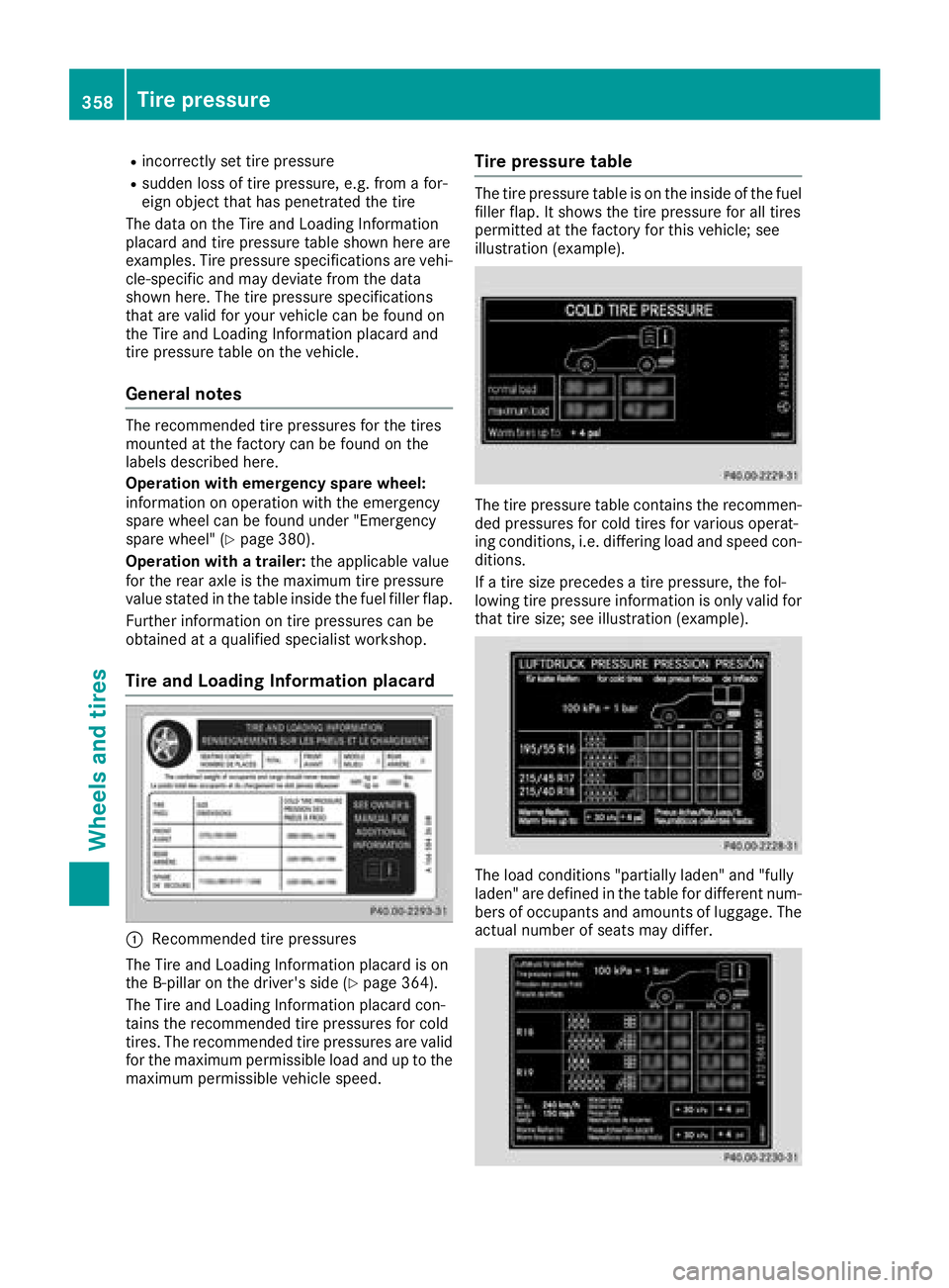
The data on the Tire and Loading Information
placard and tire pressure table shown here are
examples. Tire pressure specifications are vehi-
cle-specific and may deviate from the data
shown here. The tire pressure specifications
that are valid for your vehicle can be found on
the Tire and Loading Information placard and
tire pressure table on the vehicle.
General notes The recommended tire pressures for the tires
mounted at the factory can be found on the
labels described here.
Operation with emergency spare wheel:
information on operation with the emergency
spare wheel can be found under "Emergency
spare wheel" ( Y
page 380).
Operation with a trailer: the applicable value
for the rear axle is the maximum tire pressure
value stated in the table inside the fuel filler flap.
Further information on tire pressures can be
obtained at a qualified specialist workshop.
Tire and Loading Information placard
�C
Recommended tire pressures
The Tire and Loading Information placard is on
the B-pillar on the driver's side ( Y
page 364).
The Tire and Loading Information placard con-
tains the recommended tire pressures for cold
tires. The recommended tire pressures are valid
for the maximum permissible load and up to the
maximum permissible vehicle speed. Tire pressure table The tire pressure table is on the inside of the fuel
filler flap. It shows the tire pressure for all tires
permitted at the factory for this vehicle; see
illustration (example).
The tire pressure table contains the recommen-
ded pressures for cold tires for various operat-
ing conditions, i.e. differing load and speed con-
ditions.
If a tire size precedes a tire pressure, the fol-
lowing tire pressure information is only valid for
that tire size; see illustration (example).
The load conditions "partially laden" and "fully
laden" are defined in the table for different num-
bers of occupants and amounts of luggage. The
actual number of seats may differ.358
Tire pressure
Wheels and tires
Page 361 of 398
Some tire pressure tables show only the rim
diameters instead of the full tire size, e.g. R18 .
The rim diameter is part of the tire size and can
be found on the tire sidewall ( Y
page 369).
If the tire pressures have been set to the lower
values for lighter loads and/or lower road
speeds, the pressures should be reset to the
higher values: R
if you want to drive with an increased load
and/or R
if you want to drive at higher road speeds
The tire pressures for increased loads and/or
higher road speeds, shown in the tire pressure
table, may have a negative effect on driving
comfort.
If the tire pressure is not set correctly, this can
lead to an excessive build up of heat and a sud-
den loss of pressure.
For more information, contact a qualified spe-
cialist workshop.
Important notes on tire pressure
G WARNING
If the tire pressure drops repeatedly, the
wheel, valve or tire may be damaged. Tire
pressure that is too low may result in a tire
blow-out. There is a risk of an accident. R
Check the tire for foreign objects. R
Check whether the wheel is losing air or the
valve is leaking.
If you are unable to rectify the damage, con-
tact a qualified specialist workshop.
G WARNING
If you fit unsuitable accessories onto tire
valves, the tire valves may be overloaded and
malfunction, which can cause tire pressure
loss. Due to their design, retrofitted tire pres-
sure monitors keep the tire valve open. This
can also result in tire pressure loss. There is a
risk of an accident.
Only screw the standard valve cap or other
valve caps approved by Mercedes-Benz for
your vehicle onto the tire valve.
Use a suitable pressure gauge to check the tire
pressure. The outer appearance of a tire does not permit any reliable conclusion about the tire
pressure. On vehicles equipped with the elec-
tronic tire pressure monitor, the tire pressure
can be checked in the on-board computer.
The tire temperature and pressure increase
when the vehicle is in motion. This is dependent
on the driving speed and the load.
Therefore, you should only correct tire pres-
sures when the tires are cold.
The tires are cold: R
if the vehicle has been parked with the tires
out of direct sunlight for at least three hours
and R
if the vehicle has not been driven further than
1 mile (1.6 km)
The tire temperature changes depending on the
outside temperature, the vehicle speed and the
tire load. If the tire temperature changes by
18 ‡ (10 †), the tire pressure changes by
approximately 10 kPa (0.1 bar/1.5 psi) . Take
thi s into account when checking the pressure of
warm tires. Only correct the tire pressure if it is
too low for the current operating conditions. If
you check the tire pressure when the tires are
warm, the resulting value will be higher than if
the tires were cold. This is normal. Do not
reduce the tire pressure to the value specified
for cold tires. The tire pressure would otherwise
be too low.
Observe the recommended tire pressures for
cold tires: R
on the Tire and Loading Information placard
on the B-pillar on the driver's side R
in the tire pressure table in the fuel filler flap
( Y
page 157) R
printed in yellow on the rim of the emer-
gency/collapsible spare wheel (depending on
vehicle equipment)
Underinflated or overinflated tires
Underinflated tires
G WARNING
Tires with pressure that is too low can over-
heat and burst as a consequence. In addition,
they also suffer from excessive and/or irreg-
ular wear, which can severely impair the brak-
ing properties and the driving characteristics.
There is a risk of an accident. Tire pressure 359
Wheels and tires Z
Page 364 of 398
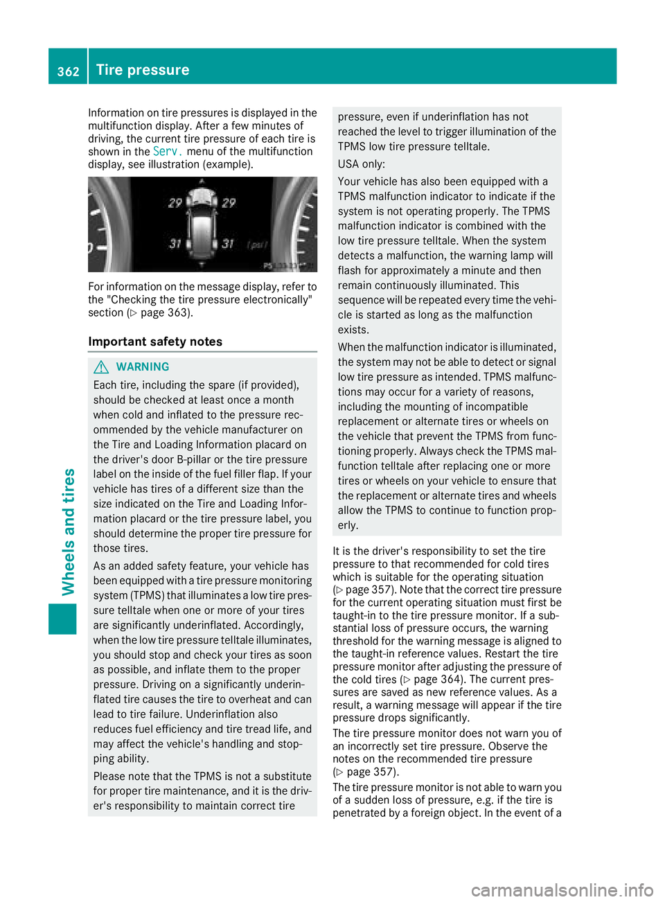
Information on tire pressures is displayed in the
multifunction display. After a few minutes of
driving, the current tire pressure of each tire is
shown in the Serv. menu of the multifunction
display, see illustration (example).
For information on the message display, refer to
the "Checking the tire pressure electronically"
section ( Y
page 363).
Important safety notes
G WARNING
Each tire, including the spare (if provided),
should be checked at least once a month
when cold and inflated to the pressure rec-
ommended by the vehicle manufacturer on
the Tire and Loading Information placard on
the driver's door B-pillar or the tire pressure
label on the inside of the fuel filler flap. If your
vehicle has tires of a different size than the
size indicated on the Tire and Loading Infor-
mation placard or the tire pressure label, you
should determine the proper tire pressure for
those tires.
As an added safety feature, your vehicle has
been equipped with a tire pressure monitoring
system (TPMS) that illuminates a low tire pres-
sure telltale when one or more of your tires
are significantly underinflated. Accordingly,
when the low tire pressure telltale illuminates,
you should stop and check your tires as soon
as possible, and inflate them to the proper
pressure. Driving on a significantly underin-
flated tire causes the tire to overheat and can
lead to tire failure. Underinflation also
reduces fuel efficiency and tire tread life, and
may affect the vehicle's handling and stop-
ping ability.
Please note that the TPMS is not a substitute
for proper tire maintenance, and it is the driv-
er's responsibility to maintain correct tire pressure, even if underinflation has not
reached the level to trigger illumination of the
TPMS low tire pressure telltale.
USA only:
Your vehicle has also been equipped with a
TPMS malfunction indicator to indicate if the
system is not operating properly. The TPMS
malfunction indicator is combined with the
low tire pressure telltale. When the system
detects a malfunction, the warning lamp will
flash for approximately a minute and then
remain continuously illuminated. This
sequence will be repeated every time the vehi-
cle is started as long as the malfunction
exists.
When the malfunction indicator is illuminated,
the system may not be able to detect or signal
low tire pressure as intended. TPMS malfunc-
tions may occur for a variety of reasons,
including the mounting of incompatible
replacement or alternate tires or wheels on
the vehicle that prevent the TPMS from func-
tioning properly. Always check the TPMS mal-
function telltale after replacing one or more
tires or wheels on your vehicle to ensure that
the replacement or alternate tires and wheels
allow the TPMS to continue to function prop-
erly.
It is the driver's responsibility to set the tire
pressure to that recommended for cold tires
which is suitable for the operating situation
( Y
page 357). Note that the correct tire pressure
for the current operating situation must first be
taught-in to the tire pressure monitor. If a sub-
stantial loss of pressure occurs, the warning
threshold for the warning message is aligned to
the taught-in reference values. Restart the tire
pressure monitor after adjusting the pressure of
the cold tires ( Y
page 364). The current pres-
sures are saved as new reference values. As a
result, a warning message will appear if the tire
pressure drops significantly.
The tire pressure monitor does not warn you of
an incorrectly set tire pressure. Observe the
notes on the recommended tire pressure
( Y
page 357).
The tire pressure monitor is not able to warn you
of a sudd en loss of pressure, e.g. if the tire is
penetra ted
by a foreign object. In the event of a362
Tire pressure
Wheels and tires
Page 366 of 398
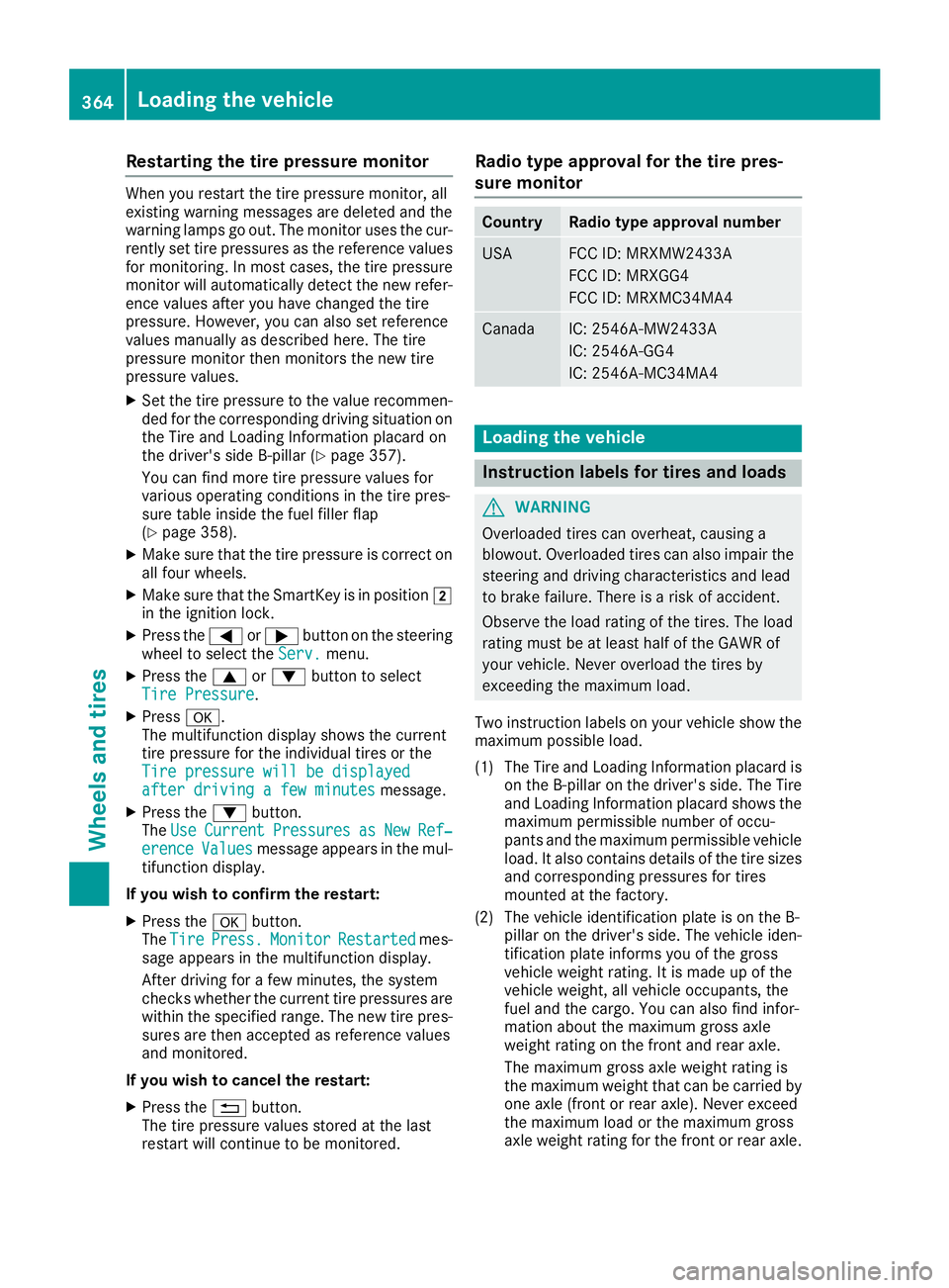
Restarting the tire pressure monitor When you restart the tire pressure monitor, all
existing warning messages are deleted and the
warning lamps go out. The monitor uses the cur-
rently set tire pressures as the reference values
for monitoring. In most cases, the tire pressure
monitor will automatically detect the new refer-
ence values after you have changed the tire
pressure. However, you can also set reference
values manually as described here. The tire
pressure monitor then monitors the new tire
pressure values. X
Set the tire pressure to the value recommen-
ded for the corresponding driving situation on
the Tire and Loading Information placard on
the driver's side B-pillar ( Y
page 357).
You can find more tire pressure values for
various operating conditions in the tire pres-
sure table inside the fuel filler flap
( Y
page 358).X
Make sure that the tire pressure is correct on
all four wheels. X
Make sure that the SmartKey is in position �H
in the ignition lock. X
Press the �Y or �e button on the steering
wheel to select the Serv. menu.X
Press the �c or �d button to select
Tire Pressure .X
Press �v .
The multifunction display shows the current
tire pressure for the individual tires or the
Tire pressure will be displayed
after driving a few minutes message.X
Press the �d button.
The Use Current Pressures as New Ref‐
erence Values message appears in the mul-
tifunction display.
If you wish to confirm the restart: X
Press the �v button.
The Tire Press. Monitor Restarted mes-
sage appears in the multifunction display.
After driving for a few minutes, the system
checks whether the current tire pressures are
within the specified range. The new tire pres-
sures are then accepted as reference values
and monitored.
If you wish to cancel the restart: X
Press the �8 button.
The tire pressure values stored at the last
restart will continue to be monitored. Radio type approval for the tire pres-
sure monitor Country Radio type approval number
USA FCC ID: MRXMW2433A
FCC ID: MRXGG4
FCC ID: MRXMC34MA4
Canada IC: 2546A-MW2433A
IC: 2546A-GG4
IC: 2546A-MC34MA4
Loading the vehicle
Instruction labels for tires and loads
G WARNING
Overloaded tires can overheat, causing a
blowout. Overloaded tires can also impair the
steering and driving characteristics and lead
to brake failure. There is a risk of accident.
Observe the load rating of the tires. The load
rating must be at least half of the GAWR of
your vehicle. Never overload the tires by
exceeding the maximum load.
Two instruction labels on your vehicle show the
maximum possible load.
(1) The Tire and Loading Information placard is
on the B-pillar on the driver's side. The Tire
and Loading Information placard shows the
maximum permissible number of occu-
pants and the maximum permissible vehicle
load. It also contains details of the tire sizes
and corresponding pressures for tires
mounted at the factory.
(2) The vehicle identification plate is on the B-
pillar on the driver's side. The vehicle iden-
tification plate informs you of the gross
vehicle weight rating. It is made up of the
vehicle weight, all vehicle occupants, the
fuel and the cargo. You can also find infor-
mation about the maximum gross axle
weight rating on the front and rear axle.
The maximum gross axle weight rating is
the maximum weight that can be carried by
one axle (front or rear axle). Never exceed
the maximum load or the maxi mum g ross
a
xle weight rating for the front or rear axle.364
Loading the vehicle
Wheels and tires
Page 368 of 398
able cargo and luggage load capacity is
650 lbs (1400 - 750 (5 x 150) = 650 lbs). X
Step 5: Determine the combined weight of
luggage and cargo being loaded on the vehi- cle. That weight may not safely exceed the
available cargo and luggage load capacity cal-
culated in step 4.
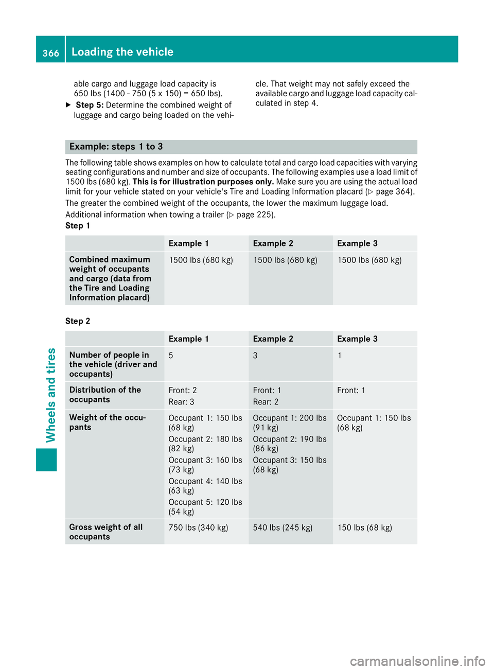
Example: steps 1 to 3 The following table shows examples on how to calculate total and cargo load capacities with varying
seating configurations and number and size of occupants. The following examples use a load limit of
1500 lbs (680 kg). This is for illustration purposes only. Make sure you are using the actual load
limit for your vehicle stated on your vehicle's Tire and Loading Information placard ( Y
page 364).
The greater the combined weight of the occupants, the lower the maximum luggage load.
Additional information when towing a trailer ( Y
page 225).
Step 1
Example 1 Example 2 Example 3
Combined maximum
weight of occupants
and cargo (data from
the Tire and Loading
Information placard) 1500 lbs (680 kg) 1500 lbs (680 kg) 1500 lbs (680 kg)
Step 2
Example 1 Example 2 Example 3
Number of people in
the vehicle (driver and
occupants) 5 3 1
Distribution of the
occupants Front: 2
Rear: 3 Front: 1
Rear: 2 Front: 1
Weight of the occu-
pants Occupant 1: 150 lbs
(68 kg)
Occupant 2: 180 lbs
(82 kg)
Occupant 3: 160 lbs
(73 kg)
Occupant 4: 140 lbs
(63 kg)
Occupant 5: 120 lbs
(54 kg) Occupant 1: 200 lbs
(91 kg)
Occupant 2: 190 lbs
(86 kg)
Occupant 3: 150 lbs
(68 kg) Occupant 1: 150 lbs
(68 kg)
Gross weight of all
occupants 750 lbs (340 kg) 540 lbs (245 kg) 150 lbs (68 kg)366
Loading the vehicle
Wheels and tires
Page 382 of 398
Notes on the vehicle equipment – always equip
the vehicle: R
with tires of the same size on a given axle (left
and right) R
with the same type of tires at a given time
(summer tires, winter tires, MOExtended
tires)
i Vehicles equipped with MOExtended tires
are not equipped with a TIREFIT kit at the fac-
tory. It is therefore recommended that you
additionally equip your vehicle with a TIREFIT
kit if you mount tires that do not feature run-
flat properties, e.g. winter tires. A TIREFIT kit
may be obtained from a qualified specialist
workshop.
Emergency spare wheel
Important safety notes
G WARNING
The wheel or tire size as well as the tire type of
the spare wheel or emergency spare wheel
and the wheel to be replaced may differ.
Mounting an emergency spare wheel may
severely impair the driving characteristics.
There is a risk of an accident.
To avoid hazardous situations: R
adapt your driving style accordingly and
drive carefully. R
never mount more than one spare wheel or
emergency spare wheel that differs in size. R
only use a spare wheel or emergency spare
wheel of a different size briefly. R
do not switch ESP ®
off.R
have a spare wheel or emergency spare
wheel of a different size replaced at the
nearest qualified specialist workshop.
Observe that the wheel and tire dimensions
as well as the tire type must be correct.
! Mercedes-AMG vehicles with
"Minispare" emergency spare wheel: only
use the "Minispare" emergency spare wheel
on the rear axle . If you mount the
"Minispare" emergency spare wheel on the
front axle, this could result in damage to the
brake system. If a tire on the front axle is defective, an intact
wheel from the rear axle must first be
replaced with the "Minispare" emergency
spare wheel. The damaged wheel on the front
axle can then be replaced by the undamaged
wheel from the rear axle.
Make sure to note the placard on the
"Minispare" emergency spare wheel.
When using an emergency spare wheel or spare
wheel of a different size, you must not exceed
the maximum speed of 50 mph (80 km/h).
You should regularly check the pressure of the
emergency spare wheel, particularly prior to
long trips, and correct the pressure as neces-
sary ( Y
page 357). The value on the wheel is
valid.
Snow chains must not be mounted on emer-
gency spare wheels.
General notes Information regarding permitted emergency
spare wheels can be found at an authorized
Mercedes-Benz Center.
Mounting the emergency spare wheel is descri-
bed under "Mounting a wheel" ( Y
page 375).
An emergency spare wheel may also be moun-
ted against the direction of rotation. Observe
the time restriction on use as well as the speed
limitation specified on the emergency spare
wheel.
Replace the tires after six years at the latest,
regardless of wear. This also applies to the
emergency spare wheel.
When you are driving with the collapsible spare
wheel mounted, the tire pressure loss warning
system or the tire pressure monitor cannot func-
tion reliably. Only restart the tire pressure loss
warning system or tire pressure monitor when
the defective wheel has been replaced with a
new wheel.
Vehicles with tire pressure monitor: after
mounting an emergency spare wheel, the sys-
tem may still display the tire pressure of the
removed wheel for a few minutes. The value dis-
played for the mounted emergency spare wheel
is not the same as the current tire pressure of
the emergency spare wheel.380
Emergency spare wheel
Wheels and tires