warning light MERCEDES-BENZ GLS 2019 Owners Manual
[x] Cancel search | Manufacturer: MERCEDES-BENZ, Model Year: 2019, Model line: GLS, Model: MERCEDES-BENZ GLS 2019Pages: 398, PDF Size: 7.3 MB
Page 285 of 398
Warning/
indicator
lamp
0051 0051
Signal type
Possible causes/consequences and 0050
0050Solutions 00B6
0051
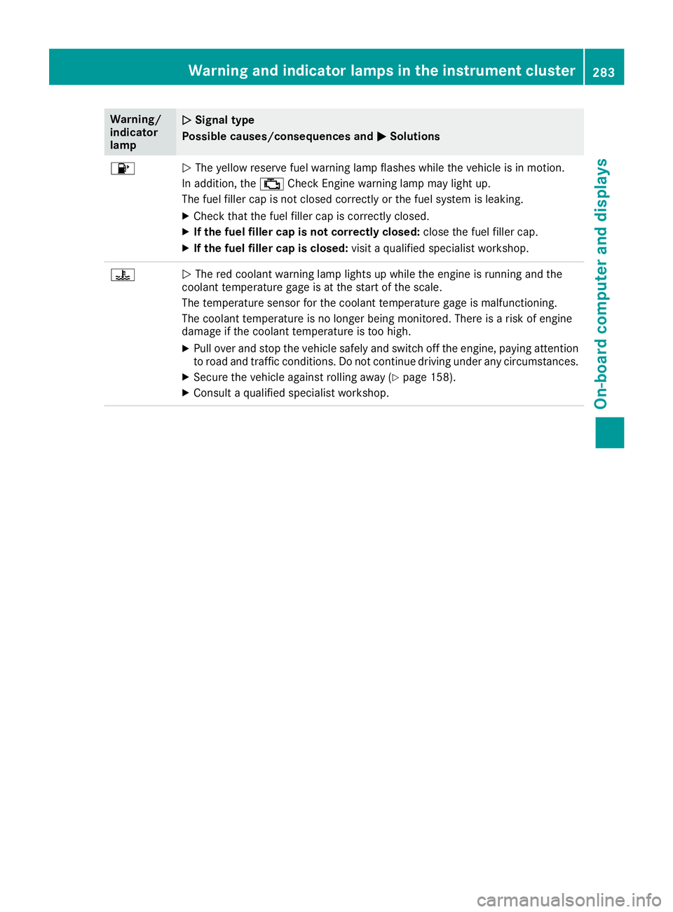
The yellow reserve fuel warning lamp flashes while the vehicle is in motion.
In addition, the 00B9Check Engine warning lamp may light up.
The fuel filler cap is not closed correctly or the fuel system is leaking.
X Check that the fuel filler cap is correctly closed.
X If the fuel filler cap is not correctly closed: close the fuel filler cap.
X If the fuel filler cap is closed: visit a qualified specialist workshop.00AC
0051
The red coolant warning lamp lights up while the engine is running and the
coolant temperature gage is at the start of the scale.
The temperature sensor for the coolant temperature gage is malfunctioning.
The coolant temperature is no longer being monitored. There is a risk of engine
damage if the coolant temperature is too high.
X Pull over and stop the vehicle safely and switch off the engine, paying attention
to road and traffic conditions. Do not continue driving under any circumstances.
X Secure the vehicle against rolling away (Y page 158).
X Consult a qualified specialist workshop. Warning and indicator lamps in the instrument cluster
283On-board computer and displays Z
Page 287 of 398
Warning/
indicator
lamp
0051 0051
Signal type
Possible causes/consequences and 0050
0050Solutions X
At coolant temperatures below 248 ‡ (120 †), drive to the nearest qualified
specialist workshop.
X Avoid heavy loads on the engine as you do so, e.g. driving in mountainous terrain
and stop-and-go traffic. Driving systems
Warning/
indicator
lamp
0051 0051
Signal type
Possible causes/consequences and 0050
0050Solutions 00BA
0051
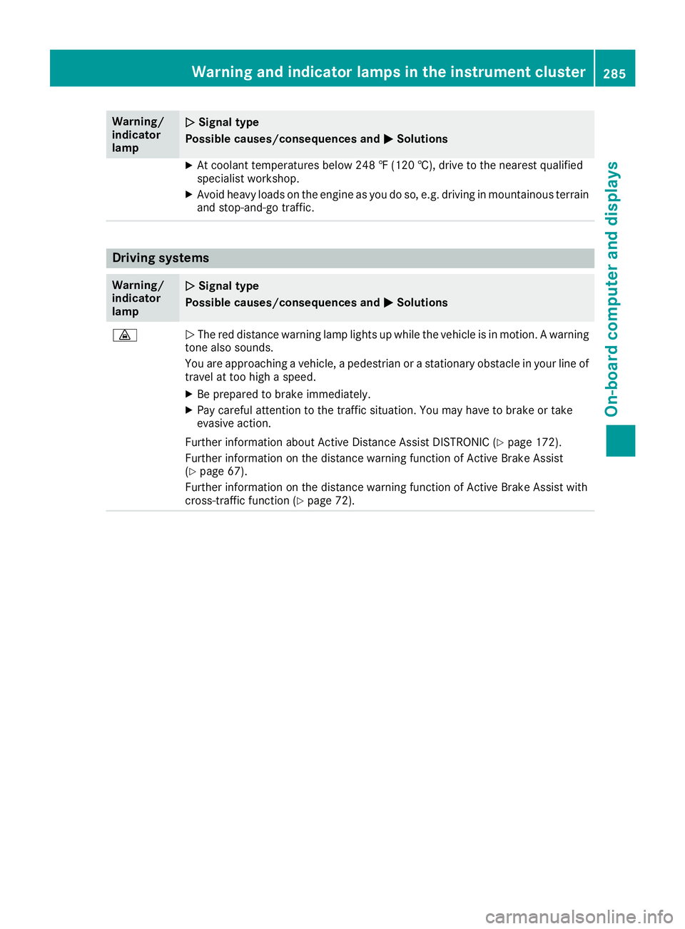
The red distance warning lamp lights up while the vehicle is in motion. A warning
tone also sounds.
You are approaching a vehicle, a pedestrian or a stationary obstacle in your line of travel at too high a speed.
X Be prepared to brake immediately.
X Pay careful attention to the traffic situation. You may have to brake or take
evasive action.
Further information about Active Distance Assist DISTRONIC (Y page 172).
Further information on the distance warning function of Active Brake Assist
(Y page 67).
Further information on the distance warning function of Active Brake Assist with
cross-traffic function (Y page 72). Warning and indicator lamps in the instrument cluster
285On-board computer and displays Z
Page 289 of 398
General notes
The multimedia system section in this Opera-
tor's Manual describes the basic principles for
operation. More information can be found in the Digital Operator's Manual. Important safety notes
G
WARNING
If you operate information systems and com-
munication equipment integrated in the vehi- cle when driving, you may be distracted from
the traffic situation. You could also lose con-
trol of the vehicle. There is a risk of an acci-
dent.
Only operate this equipment when the traffic
situation permits. If you are not sure that this
is possible, park the vehicle paying attention
to traffic conditions and operate the equip-
ment when the vehicle is stationary.
You must observe the legal requirements for the country in which you are currently driving whenoperating the multimedia system.
The multimedia system calculates the route to
the destination without taking the following into
account, for example:
R traffic lights
R stop and yield signs
R parking or stopping restrictions
R road narrowing
R other road and traffic rules and regulations
The multimedia system may give incorrect nav-
igation recommendations if the actual street/
traffic situation does not correspond with the
digital map's data.
For example:
R a diverted route
R the road layout or the direction of a one-way
street has been changed
For this reason, you must always observe road
and traffic rules and regulations during your
journey. Road and traffic rules and regulations
always have priority over multimedia system
driving recommendations. Navigation announcements are intended to
direct you while driving without diverting your
attention from the road and driving.
Please always use this feature instead of con-
sulting the map display for directions. Looking
at the icons or map display can distract you from
traffic conditions and driving, and increase the
risk of an accident.
This equipment complies with FCC radiation
exposure limits set forth for uncontrolled equip-
ment and meets the FCC radio frequency (RF)
Exposure Guidelines in Supplement C to OET65.
This equipment has very low levels of RF energy that is deemed to comply without maximum
permissive exposure evaluation (MPE). How-
ever, it is recommended to install it at a distance
of at least 8 inches (approx. 20 cm) between the
radiation source and a person's body (not
including limbs such as hands, wrists, feet and
legs). G
WARNING
Modifications to electronic components, their software as well as wiring can impair their
function and/or the function of other net-
worked components. In particular, systems
relevant to safety could also be affected. As a
result, these may no longer function as inten-
ded and/or jeopardize the operating safety of
the vehicle. There is an increased risk of an
accident and injury.
Never tamper with the wiring as well as elec-
tronic components or their software. You
should have all work to electrical and elec-
tronic equipment carried out at a qualified
specialist workshop. Function restrictions
For safety reasons, some functions are restric-
ted or unavailable while the vehicle is in motion. You will notice this, for example, because either
you will not be able to select certain menu items or a message will appear to this effect. Function restrictions
287Multimedia system Z
Page 302 of 398
X
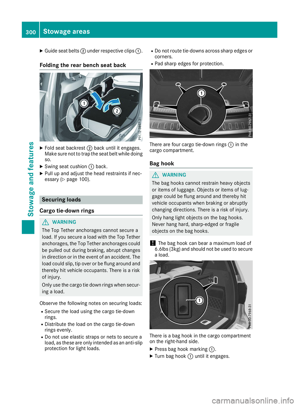
Guide seat belts 0044under respective clips 0043.
Folding the rear bench seat back X
Fold seat backrest 0044back until it engages.
Make sure not to trap the seat belt while doing so.
X Swing seat cushion 0043back.
X Pull up and adjust the head restraints if nec-
essary (Y page 100). Securing loads
Cargo tie-down rings G
WARNING
The Top Tether anchorages cannot secure a
load. If you secure a load with the Top Tether
anchorages, the Top Tether anchorages could be pulled out during braking, abrupt changes
in direction or in the event of an accident. The load could slip, tip over or be flung around and
thereby hit vehicle occupants. There is a risk
of injury.
Only use the cargo tie down rings when secur-
ing a load.
Observe the following notes on securing loads: R Secure the load using the cargo tie-down
rings.
R Distribute the load on the cargo tie-down
rings evenly.
R Do not use elastic straps or nets to secure a
load, as these are only intended as an anti-slip protection for light loads. R
Do not route tie-downs across sharp edges or
corners.
R Pad sharp edges for protection. There are four cargo tie-down rings
0043in the
cargo compartment.
Bag hook G
WARNING
The bag hooks cannot restrain heavy objects
or items of luggage. Objects or items of lug-
gage could be flung around and thereby hit
vehicle occupants when braking or abruptly
changing directions. There is a risk of injury.
Only hang light objects on the bag hooks.
Never hang hard, sharp-edged or fragile
objects on the bag hooks.
! The bag hook can bear a maximum load of
6.6lbs (3kg) and should not be used to secure
a load. There is a bag hook in the cargo compartment
on the right-hand side.
X Press bag hook marking 0043.
X Turn bag hook 0043until it engages. 300
Stowage areasStowage and features
Page 307 of 398
X
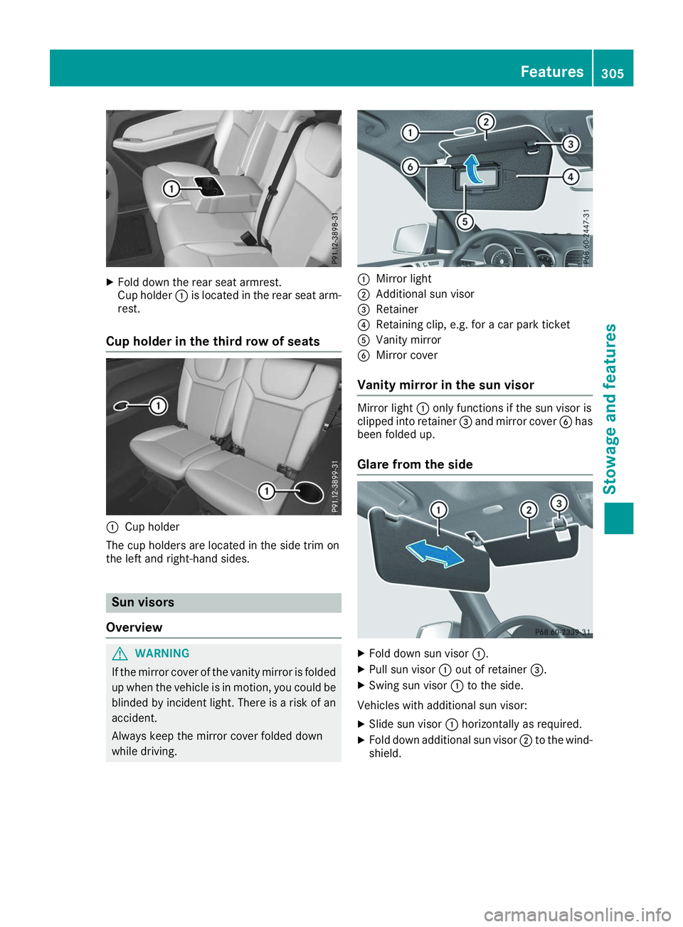
Fold down the rear seat armrest.
Cup holder 0043is located in the rear seat arm-
rest.
Cup holder in the third row of seats 0043
Cup holder
The cup holders are located in the side trim on
the left and right-hand sides. Sun visors
Overview G
WARNING
If the mirror cover of the vanity mirror is folded up when the vehicle is in motion, you could be
blinded by incident light. There is a risk of an
accident.
Always keep the mirror cover folded down
while driving. 0043
Mirror light
0044 Additional sun visor
0087 Retainer
0085 Retaining clip, e.g. for a car park ticket
0083 Vanity mirror
0084 Mirror cover
Vanity mirror in the sun visor Mirror light
0043only functions if the sun visor is
clipped into retainer 0087and mirror cover 0084has
been folded up.
Glare from the side X
Fold down sun visor 0043.
X Pull sun visor 0043out of retainer 0087.
X Swing sun visor 0043to the side.
Vehicles with additional sun visor:
X Slide sun visor 0043horizontally as required.
X Fold down additional sun visor 0044to the wind-
shield. Features
305Stowage and features Z
Page 309 of 398
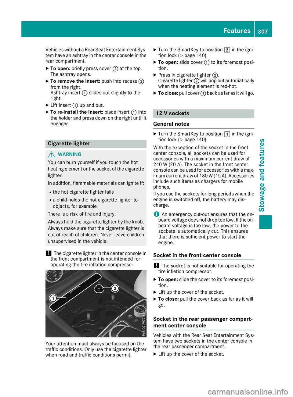
Vehicles without a Rear Seat Entertainment Sys-
tem have an ashtray in the center console in the rear compartment.
X To open: briefly press cover 0044at the top.
The ashtray opens.
X To remove the insert: push into recess0087
from the right.
Ashtray insert 0043slides out slightly to the
right.
X Lift insert 0043up and out.
X To re-install the insert: place insert0043into
the holder and press down on the right until it
engages. Cigarette lighter
G
WARNING
You can burn yourself if you touch the hot
heating element or the socket of the cigarette lighter.
In addition, flammable materials can ignite if:
R the hot cigarette lighter falls
R a child holds the hot cigarette lighter to
objects, for example
There is a risk of fire and injury.
Always hold the cigarette lighter by the knob.
Always make sure that the cigarette lighter is
out of reach of children. Never leave children unsupervised in the vehicle.
! The cigarette lighter in the center console in
the front compartment is not intended for
operating the tire inflation compressor. Your attention must always be focused on the
traffic conditions. Only use the cigarette lighter
when road and traffic conditions permit. X
Turn the SmartKey to position 0048in the igni-
tion lock (Y page 140).
X To open: slide cover 0043to its foremost posi-
tion.
X Press in cigarette lighter 0044.
Cigarette lighter 0044will pop out automatically
when the heating element is red-hot.
X To close: pull cover 0043back as far as it will go. 12 V sockets
General notes X
Turn the SmartKey to position 0047in the igni-
tion lock (Y page 140).
With the exception of the socket in the front
center console, all sockets can be used for
accessories with a maximum current draw of
240 W (20 A). The socket in the front center
console can be used for accessories with a max-
imum current draw of 180 W(15 A). Accessories
include such items as chargers for mobile
phones.
If you use the sockets for long periods when the engine is switched off, the battery may dis-
charge.
i An emergency cut-out ensures that the on-
board voltage does not drop too low. If the on-
board voltage is too low, the power to the
sockets is automatically cut. This ensures
that there is sufficient power to start the
engine.
Socket in the front center console !
The socket is not suitable for operating the
tire inflation compressor.
X To open: slide the cover to its foremost posi-
tion.
X Lift up the cover of the socket.
X To close: pull the cover back as far as it will
go.
Socket in the rear passenger compart-
ment center console Vehicles with the Rear Seat Entertainment Sys-
tem have two sockets in the center console in
the rear passenger compartment.
X Lift up the cover of the socket. Features
307Stowage and features Z
Page 311 of 398
Problems with the 115 V power socket
Problem
Possible causes/consequences and
0050
0050Solutions The warning lamp on the
115 V power socket is
not lit. The on-board voltage is too low because the battery is too weak.
X Start the engine.
or X Charge the battery (Y page 342).
If the indicator lamp still does not light up: X Visit a qualified specialist workshop. The temperature of the DC/AC converter is temporarily too high.
X Remove the electronic device connector from the 115 V socket.
X Let the DC/AC converter cool down.
If the indicator lamp still does not light up after cooling down the
converter:
X Visit a qualified specialist workshop. You have connected an electronic device that has a constant nominal
power of less than 150 watts, but has a very high switch-on current.
This device will not work. If you connect such a device, the 115 V
power socket will not supply it with power.
X Connect a suitable electronic device. mbrace
General notes The mbrace system is only available in the USA.
A license agreement must be in place in order to
activate the mbrace service. Make sure that
your system is activated and operational. To
register, press the 00D9Info call button. If any of
the steps mentioned are not carried out, the
system may not be activated.
If you have questions about the activation, con- tact one of the following telephone hotlines:
Mercedes-Benz Customer Assistance Center at
1-800 FOR-MERCEDES (1-800-367-6372) or
1-866-990-9007
Shortly after successfully registering with the
mbrace service, a user ID and password will be
sent to you by mail. You can use this password
to log onto the mbrace area under "Owners
Online" at http://www.mbusa.com. The system is available if:
R it has been activated and is operational
R the corresponding mobile phone network is
available for transmitting data to the Cus-
tomer Center
R a service subscription is available
Determining the location of the vehicle on a map
is only possible if:
R GPS reception is available
R the vehicle position can be forwarded to the
Customer Assistance Center
The mbrace system To adjust the volume during a call, proceed as
follows:
X Press the 0081or0082 button on the multi-
function steering wheel.
or X Use the multimedia system volume control. Features
309Stowage and features Z
Page 312 of 398
The system offers various services, e.g.:
R Automatic and manual emergency call
R Roadside Assistance call
R Info call
You can find information and a description of all
available features under "Owners Online" at
http://www.mbusa.com.
System self-test After you have switched on the ignition, the sys-
tem carries out a self-diagnosis.
A malfunction in the system has been detected
if one of the following occurs:
R The indicator lamp in the SOS button does not
come on during the system self-test.
R The indicator lamp in the 0052Roadside
Assistance call button does not light up dur-
ing self-diagnosis of the system.
R The indicator lamp in the 00D9Info call button
does not light up during the system self-diag-
nosis.
R The indicator lamp in one or more of the fol-
lowing buttons continues to light up red after
the system self-diagnosis:
- SOS button
- 0052 Roadside Assistance call button
- 00D9 Info call button
R The Inoperative
Inoperative or theService Not Service Not
Activated
Activated message appears in the multi-
function display after the system self-diagno- sis.
If a malfunction is indicated as outlined above,
the system may not operate as expected. In the
event of an emergency, help will have to be
summoned by other means.
Have the system checked at the nearest author- ized Mercedes-Benz Center or call the following
telephone assistance services:
Mercedes-Benz Customer Assistance Center at
1-800-FOR-MERCedes (1-800-367-6372) or
1-866-990-9007. Emergency call Important safety notes
G
WARNING
It can be dangerous to remain in the vehicle,
even if you have pressed the SOS button in an emergency if:
R you see smoke inside or outside of the vehi-
cle, e.g. if there is a fire after an accident
R the vehicle is on a dangerous section of
road
R the vehicle is not visible or cannot easily be
seen by other road users, particularly whendark or in poor visibility conditions
There is a risk of an accident and injury.
Leave the vehicle immediately in this or simi-
lar situations as soon as it is safe to do so.
Move to a safe location along with other vehi-
cle occupants. In such situations, secure the
vehicle in accordance with national regula-
tions, e. g. with a warning triangle.
General notes
Observe the notes on system activation
(Y page 309).
The emergency call is triggered automatically if
an air bag is deployed or an Emergency Ten-
sioning Device is triggered. You cannot end an
automatically triggered emergency call yourself.
An emergency call can also be initiated man-
ually.
As soon as the emergency call has been initi-
ated, the indicator lamp in the SOS button
flashes. The Connecting Call Connecting Call message
appears in the multifunction display.
The audio output is muted.
Once the connection has been made, the Call Call
Connected
Connected message appears in the multifunc-
tion display.
All important information on the emergency is
transmitted, for example:
R Current location of the vehicle (as determined
by the GPS system)
R Vehicle identification number
R Information on the severity of the accident
Shortly after the emergency call has been initi-
ated, a voice connection is automatically estab- 310
FeaturesStowage and features
Page 318 of 398
The data you receive contains the following
information:
R the location where the speed limit was excee-
ded
R the time at which the speed limit was excee-
ded
R the selected speed limit which was exceeded
Geo fencing Geo fencing allows you to select areas which the
vehicle should not enter or leave. You will be
informed if the vehicle crosses the boundaries
of the selected areas. You can select the way in which you receive this information beforehand.
Possible options include text message, e-mail or an automated call.
The area can be determined as either a circle or
a polygon with a maximum of ten corners. You
can specify up to ten areas simultaneously. Dif- ferent settings are possible for each area.
These settings can be called up under "Owners
Online" at http://www.mbusa.com.
Alternatively, you can also trigger an Info call
and notify the customer service representative
that you wish to activate geo-fencing.
Currently inactive areas can be activated by text
message.
Triggering the vehicle alarm With this function, you can trigger the vehicle's
panic alarm via text message. An alarm sounds
and the exterior lighting flashes. Depending on
the setting, the panic alarm lasts five or ten sec-
onds. Afterwards, the alarm switches off. Garage door opener
General notes The HomeLink
®
garage door opener integrated
in the rear-view mirror allows you to operate up to three different door and gate systems.
Use the integrated garage door opener only on
garage doors that:
R they are equipped with a safety stop and
reverse feature
R they conform to the current U.S. safety stand-
ards When it has been programmed, the integrated
garage door opener in the rear-view mirror will
assume the function of the garage door sys-
tem's remote control. Please also read the oper-
ating instructions for the garage door system.
When programming a garage door opener, park the vehicle outside the garage. Do not leave the
engine running while programming.
Certain garage door drives are incompatible
with the integrated garage door opener. If you
have difficulty programing the integrated garage
door opener, contact a Mercedes-Benz Service
Center.
Alternatively, you can call the following tele-
phone assistance services:
R USA: Mercedes-Benz Customer Assistance
Center at 1-800-FOR-MERCedes
R Canada: Customer Service at
1-800-387-0100
R HomeLink ®
hotline 1-800-355-3515 (free of
charge)
More information on HomeLink ®
and/or com-
patible products is also available on the Internet
at http://www.homelink.com.
Notes on the declaration of conformity
(Y page 30).
USA: FCC ID: CB2HMIHL4
Canada: IC: 279B-HMIHL4
Important safety notes G
WARNING
When you operate or program the door with
the integrated garage door opener, persons in the range of movement of the door may
become trapped or be struck by the door.
There is a risk of injury.
When using the integrated garage door
opener, always make sure that nobody is
within the range of movement of the door. G
DANGER
Combustion engines emit poisonous exhaust
gases such as carbon monoxide. Inhaling
these exhaust gases is hazardous to health
and can result in poisoning. There is a risk of
fatal injury. Therefore, never leave the engine running an enclosed space without adequate
ventilation. 316
FeaturesStowage and features
Page 321 of 398
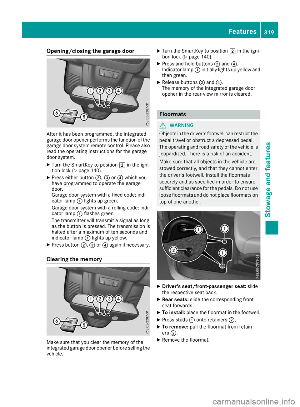
Opening/closing the garage door
After it has been programmed, the integrated
garage door opener performs the function of the
garage door system remote control. Please also
read the operating instructions for the garage
door system.
X Turn the SmartKey to position 0048in the igni-
tion lock (Y page 140).
X Press either button 0044,0087or0085 which you
have programmed to operate the garage
door.
Garage door system with a fixed code: indi-
cator lamp 0043lights up green.
Garage door system with a rolling code: indi-
cator lamp 0043flashes green.
The transmitter will transmit a signal as long
as the button is pressed. The transmission is
halted after a maximum of ten seconds and
indicator lamp 0043lights up yellow.
X Press button 0044,0087or0085 again if necessary.
Clearing the memory Make sure that you clear the memory of the
integrated garage door opener before selling the vehicle. X
Turn the SmartKey to position 0048in the igni-
tion lock (Y page 140).
X Press and hold buttons 0044and 0085.
Indicator lamp 0043initially lights up yellow and
then green.
X Release buttons 0044and 0085.
The memory of the integrated garage door
opener in the rear-view mirror is cleared. Floormats
G
WARNING
Objects in the driver's footwell can restrict the pedal travel or obstruct a depressed pedal.
The operating and road safety of the vehicle is
jeopardized. There is a risk of an accident.
Make sure that all objects in the vehicle are
stowed correctly, and that they cannot enter
the driver's footwell. Install the floormats
securely and as specified in order to ensure
sufficient clearance for the pedals. Do not use loose floormats and do not place floormats on
top of one another. X
Driver's seat/front-passenger seat: slide
the respective seat back.
X Rear seats: slide the corresponding front
seat forwards.
X To install: place the floormat in the footwell.
X Press studs 0043onto retainers 0044.
X To remove: pull the floormat from retain-
ers 0044.
X Remove the floormat. Features
319Stowage and features Z