change wheel MERCEDES-BENZ GLS SUV 2020 Owners Manual
[x] Cancel search | Manufacturer: MERCEDES-BENZ, Model Year: 2020, Model line: GLS SUV, Model: MERCEDES-BENZ GLS SUV 2020Pages: 549, PDF Size: 9.9 MB
Page 6 of 549
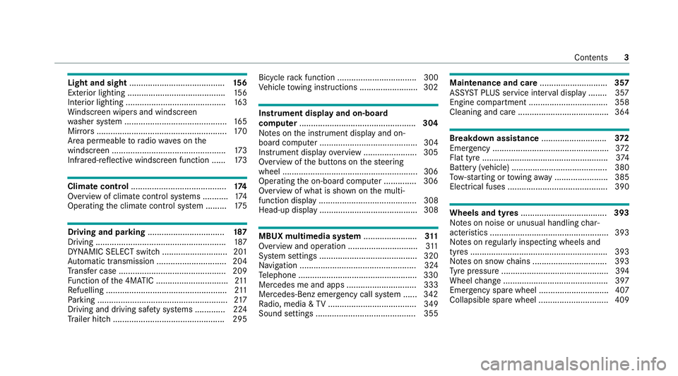
Light and sight
......................................... 15 6
Exterior lighting .......................................... 15 6
Interior lighting ...........................................1 63
Wi ndsc reen wipers and windscreen
wa sher sy stem ............................................ 16 5
Mir rors ........................................................ 17 0
Area pe rmeable toradio wav es on the
windscreen ................................................ .173
Infrared-reflective windscreen function ...... 173Climate control
......................................... 174
Overview of climate contro l systems ........... 174
Operating the climate control sy stem ......... 175 Driving and pa
rking ................................. 187
Driving ........................................................ 187
DY NA MIC SELECT switch ............................2 01
Au tomatic transmission .............................. 204
Tr ans fer case .............................................. 209
Fu nction of the 4MATIC ...............................2 11
Re fuelling .................................................... 211
Pa rking ........................................................ 217
Driving and driving sa fety sy stems .............2 24
Tr ailer hit ch................................................ 295 Bicycle
rack function .................................. 300
Ve hicle towing instructions ........................ .302 Instrument display and on-board
comp
uter.................................................. 304
No tes on the instrument display and on-
board computer .......................................... 304
Instrument display overview ...................... .305
Overview of the buttons on thesteering
wheel ..........................................................3 06
Operating the on-board computer .............. 306
Overview of what is shown on the multi‐
function display .......................................... 308
Head-up display .......................................... 308 MBUX multimedia sy
stem ....................... 311
Overview and operation .............................. 311
Sy stem settings .......................................... 320
Na vigation .................................................. 324
Te lephone .................................................. .330
Mercedes me and apps .............................. 333
Mercedes-Benz emer gency call sy stem ...... 342
Ra dio, media & TV...................................... 349
Sound settings ........................................... 355 Main
tenance and care ............................. 357
ASS YST PLUS service inter val display ........ 357
Engine compartment .................................. 358
Cleaning and care ...................................... .364 Breakdown assistance
............................372
Emergency ................................................. .372
Flat tyre ...................................................... 374
Battery (vehicle) ......................................... 380
To w- starting or towing away ....................... 385
Electrical fuses ........................................... 390 Wheels and tyres
..................................... 393
No tes on noise or unusual handling char‐
acteristics .................................................. .393
No tes on regular lyinspecting wheels and
tyres .......................................................... .393
No tes on snow chains ................................ 393
Ty re pressure .............................................. 394
Wheel change ............................................ .397
Emergency spare wheel .............................. 407
Collapsible spare wheel .............................. 409 Contents
3
Page 39 of 549
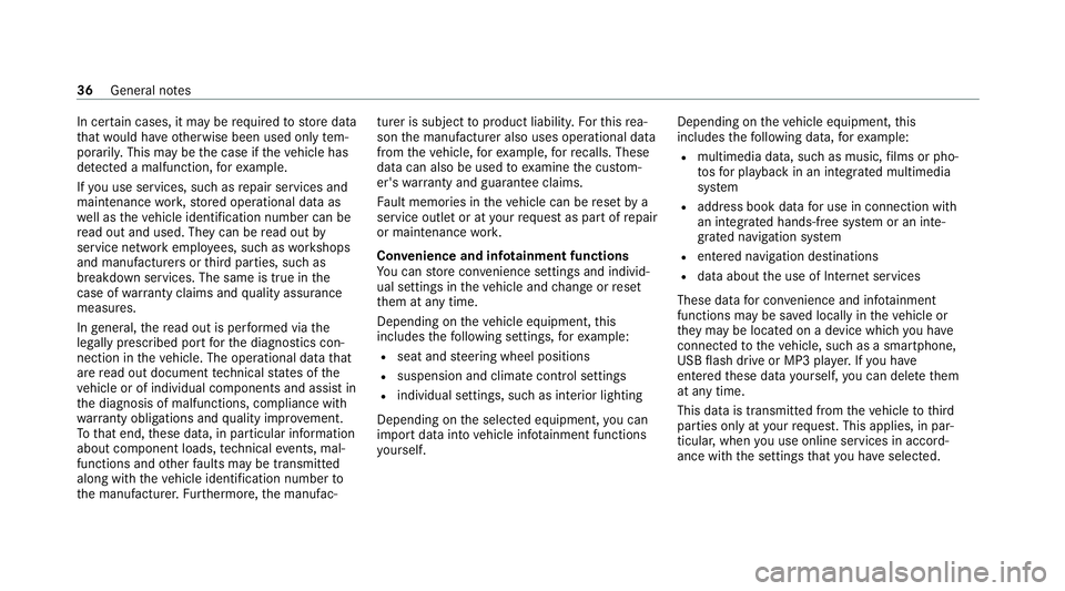
In cer
tain cases, it may be requ ired tostore data
th at wo uld ha veotherwise been used only tem‐
porarily. This may be the case if theve hicle has
de tected a malfunction, forex ample.
If yo u use services, such as repair services and
maintenance work,st ored operational data as
we ll as theve hicle identification number can be
re ad out and used. They can be read out by
service network emplo yees, such as workshops
and manufacturers or third parties, such as
breakdown services. The same is true in the
case of warranty claims and quality assurance
measures.
In general, there ad out is per form ed via the
legally prescribed port forth e diagnostics con‐
nection in theve hicle. The operational data that
are read out document tech nical states of the
ve hicle or of individual components and assist in
th e diagnosis of malfunctions, compliance with
wa rranty obligations and quality impr ovement.
To that end, these data, in particular information
about component loads, tech nical events, mal‐
functions and other faults may be transmit ted
along with theve hicle identification number to
th e manufacturer. Furthermore, the manufac‐ turer is subject
toproduct liability. Forth is rea‐
son the manufacturer also uses operational data
from theve hicle, forex ample, forre calls. These
da ta can also be used toexamine the cus tom‐
er's warranty and guarantee claims.
Fa ult memories in theve hicle can be reset by a
service outlet or at your requ est as part of repair
or maintenance work.
Con venience and inf otainment functions
Yo u can store con venience settings and individ‐
ual settings in theve hicle and change or reset
th em at any time.
Depending on theve hicle equipment, this
includes thefo llowing settings, forex ample:
R seat and steering wheel positions
R suspension and climate control settings
R individual settings, such as interior lighting
Depending on the selected equipment, you can
import data into vehicle inf otainment functions
yo urself. Depending on
theve hicle equipment, this
includes thefo llowing data, forex ample:
R multimedia data, such as music, films or pho‐
to sfo r playback in an integrated multimedia
sy stem
R address book data for use in connection with
an integrated hands-free sy stem or an inte‐
grated navigation sy stem
R entered navigation destinations
R data about the use of Internet services
These data for con venience and inf otainment
functions may be sa ved locally in theve hicle or
th ey may be located on a device which you ha ve
connected totheve hicle, such as a smartphone,
USB flash drive or MP3 pla yer.If yo u ha ve
entered these data yourself, you can dele tethem
at any time.
This data is transmit ted from theve hicle tothird
parties only at your requ est. This applies, in par‐
ticular, when you use online services in accord‐
ance with the settings that you ha veselected. 36
General no tes
Page 119 of 549
st
eering wheel and the mir ror and fas‐
te nyo ur seat belt. &
WARNING Risk of inju rydue tohead
re stra ints not being fitted or being adjus‐
te d incor rectly
If head restra ints ha venot been ins talled or
ha ve not been adjus ted cor rectly, there is an
increased risk of injury in the head and neck
area, e.g. in theev ent of an accident or when
braking. #
Alw ays drive with the head restra ints
fi tted. #
Before driving off, ma kesure forev ery
ve hicle occupant that the cent reofthe
head restra int supports the back of the
head at about eye le vel. Do not inter
change the head restra ints of the
front and rear seats. Otherwise, you will not be
able toadjust the height and angle of the head
re stra ints cor rectl y. Ad
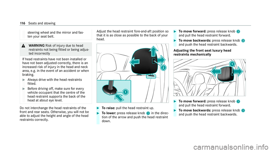
just the head restra int fore -and-aft position so
th at it is as close as possible tothe back of your
head. #
Toraise: pullthe head restra int up. #
Tolowe r:press release knob 1inthe direc‐
tion of the ar row and push the head restra int
down. #
Tomo veforw ard: press release knob 2
and pull the head restra int forw ard. #
Tomo vebackwards: pressrelease knob 2
and push the head restra int backwards.
Ad justing the front seat luxury head
re stra ints mechanically #
Tomo veforw ard: press release knob 1
and pull the head restra int forw ard. #
Tomo vebackwards: pressrelease knob 1
and push the head restra int backwards. 11 6
Seats and stowing
Page 123 of 549
Setting automatic seat adjustment
&
WARNING Risk of becoming trapped
du ring adjustment of the driver's seat
af te r calling up a driver profile
Selecting a user profile may trigger an
adju stment of the driver's seat tothe posi‐
tion sa ved under the user profile. You or
ot her vehicle occupants could be injured in
th e process. #
Make sure that when the position of
driver's seat is being adjus ted using the
multimedia sy stem, no people or body
parts are in the seat's range of mo ve‐
ment.
If th ere is a risk of someone becoming trap‐
ped, stop the adjustment process immedi‐
ately: #
a)Tapth ewa rning message on the
media displa y.
or #
b) Press a memory position button or a
seat adjustment switch on the driver's
door.
The adjustment process will be stop‐
ped. Re
quirements:
R Adapting the driver's seat and steering wheel
position tothe body size: automatic seat
adjustment has been switched on.
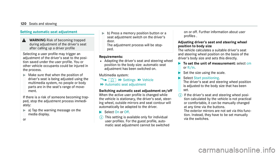
Multimedia sy stem:
4 © 5
Settings 5
Vehicle
5 Automatic seat adjustment
Switching automatic seat adjustment on/off
When the active user profile is changed while
th eve hicle is stationar y,the driver's seat, steer‐
ing wheel, outside mir rors and seat con tour will
automatically be adap tedto the driver. #
Select OnorOff.
% This setting is available on lyfor individual
user profiles. Forth e guest profile, auto‐
matic seat adjustment cann otbe switched on or off.
Further information about user
profiles .
Ad justing driver's seat and steering wheel
position tobody size
The vehicle calculates a suitable driver's seat
and steering wheel position on the basis of the
driver's body size and sets this directly. #
Toset the unit of measurement: selectcm
or ft/in. #
Set the size using the scale. #
Select Start positioning.
The driver's seat and steering wheel position
is adjus tedto the body size that has been
set.
% Ifth e driver's seat and steering wheel posi‐
tion calculated bytheve hicle is not practical
or comfor table, it can be manually changed
at any time via the buttons.
The exterior mir rors are not set via this func‐
tion. Ins tead, they have tobe set manually
via the switches. 12 0
Seats and stowing
Page 183 of 549
St
ationary heater/ventilation St
ationary heater/ventilation function
R The air inside theve hicle is heated or ventila‐
te dto the set temp erature.
R The air inside theve hicle cannot be cooled
down to temperatures below the outside
te mp erature.
R Ifth e outside temp erature changes, ventila‐
tion mode au tomatical lyswitches toheating
mode or heating mode automatically
switches toventilation mode.
The stationary heater and theex haust gas outlet
are situated behind theright-hand front wheel.
Switching thest ationary heater/ventilation
on/off via the operating unit &
DANG ER Risk of fata l injury due topoi‐
sonous exhaust gases
If th eta ilpipe is bloc ked or suf ficient ventila‐
tion is not possible, poisonous exhaust gases
such as carbon monoxide may enter theve hi‐
cle. This is the case in enclosed spaces or if
th eve hicle gets stuck in sn ow,fo rex ample. #
Alw ays switch thest ationary heater off
in enclosed spaces without an air
ex traction sy stems, e.g. in garage s. #
Keep theta ilpipe and the area around
th eve hicle free from snow when the
engine or thest ationary heater are run‐
ning. #
Open a window on the windward side of
th eve hicle toensure an adequate sup‐
ply of fresh air. &
WARNING Risk offire due tohot station‐
ary heater components and exhaust
ga ses
Flammable materials such as lea ves, grass or
twigs may ignite. #
When thest ationary heater is swit ched
on, make sure that:
R hot vehicle parts do not come into
contact with flammable materials.
R theex haust gas can flow out of the
st ationary heater exhaust pipe
unhindered. R
theex haust gas does not come into
contact with flammable materials. *
NO
TEBattery discharge caused bysta‐
tionary heater or stationary ventilation
operation Ope
rating thest ationary heater or stationary
ve ntilation drains the batter y. #
After heating or ventilating theve hicle
twice, drive for a longer period of time. Re
quirements:
R The fuel tank is su fficiently full.
% Please no tethat if theta nk fill le vel is too
lo w, it can result in function restrictions dur‐
ing auxilia ryheating operation. #
Set the desired temp erature using thew
button. #
Press the& button.
The red or blue indicator lamp on the&
button will light up or go out. 18 0
Climate cont rol
Page 198 of 549
#
Alw ays drive on inclines in the line of
fa ll (straight up or down) and do not
turn. &
WARNING Risk offire due toflammable
materials on hot parts of theex haust
sy stem
Flammable material such as lea ves, grass or
twigs may ignite if they come into contact
wi th hot parts of theex haust sy stem. #
When driving on unpa vedro ads or off-
ro ad, regular lych eck theve hicle under‐
side. #
Remo vetrapped plants or other flam‐
mable material, in particular. #
Ifth ere is damage, consult a qualified
specialist workshop immediately. When driving off-road, sand, mud and
water or
wate r mixed with oil may getinto the brakes.
This may lead toare duction in braking ef fect or
tot al brake failure as a result of increased wear.
The braking characteristics will vary depending
on the material that has entered the sy stem. Clean
the brakes af ter driving off-road. If you
th en notice reduced braking ef fect or hear
scraping noises, ha vethe brake sy stem checked
at a qualified specialist workshop. Adapt your
driving style to thech anged braking characteris‐
tics.
* NO
TEDama gecaused bydriving over
obs tacles The
vehicle can be damaged by:
R driving up onto high kerbs or unpa ved
ro ads.
R quickly driving over obs tacles su chas
ke rbs, speed bumps or po tholes.
R heavy objects hitting the underbody or
ch assis components. #
Do not drive over obs tacles that could
damage theve hicle. #
Check theve hicle regular lyfor dama ge
during off-road driving. #
Adjust theve hicle speed tosuit the
ro ad sur face conditions. #
Ifth ere is damage, consult a qualified
specialist workshop immediately. +
ENVIRONMENTAL
NOTEEnvironmental
dama gedue tonon-obser vance of pro‐
hibition signs Environmental pr
otection has priority. Treat
nature with respect. #
Be sure toobser veprohibition signs. Checklist before driving off-road
Check
thefo llowing points before driving off-
ro ad:
R Fuel le vel
R Vehicles with a diesel engine: AdBlue ®
le vel
R Engine oil le vel:fill engine oil tothe maxi‐
mum le velto ensure full gradeability
(/ page 360).
R Tyre-change tool kit and spare wheel
R Tyres and wheels Driving and parking
19 5
Page 237 of 549
A
stored speed appears along with theh dis‐
pla y.
% The segments extending from the cur rent
st ored speed tothe end of the scale, or to
th e set winter tyre limit, light up in the
speedome ter.
Sy stem limits
Cruise control may be unable tomaintain the
st ored speed on uphill gradients. The stored
speed is resumed when the gradient evens out.
Change into a lo werge ar in good time on long
and steep downhill gradients. Take particular
no te ofthis when driving a laden vehicle. By
doing so, you will make use of the engine's brak‐
ing ef fect. This relie vesth e load on the brake
sy stem and pr events the brakes from overheat‐
ing and wearing tooqu ickl y.
Do not use cruise control in thefo llowing situa‐
tions:
R In traf fic situations whi chrequ ire frequent
ch anges of speed, e.g. in heavy traf fic, on
winding roads. R
On slippe ryroads. Accelerating can cause
th e drive wheels tolose traction and the
ve hicle could then skid.
R Ifyo u are driving when visibility is poor.
Fu nction of the limiter
The limiter restricts the speed of theve hicle. To
re duce the speed tothe set speed, the limiter
applies the brakes automaticall y.
Yo u can limit the speed as follo ws:
R Variable: for a short-term speed restriction,
e.g. in built-up areas
R Perm anen t:for a longer-term speed restric‐
tion, e.g. in winter tyre mode
Yo u can store any speed abo ve20 km/h up to
th e maximum design speed or up tothe set win‐
te r tyre limit. You can also per form settings
while theve hicle is stationary if theve hicle has
been star ted.
Obser vethe no tes on driving sy stems and your
re sponsibility; you may otherwise failto recog‐
nise dangers (/ page 224).
Mercedes‑AMG vehicles: the limiter is available
up toa maximum speed of 250 km/h. Displ
ays on the multifunction display
R È (grey):va riable limiter is selec ted but
not yet acti vated.
R È (green): variable limiter is activated.
A stored speed appears along with theÈ dis‐
pla y.The segments in the speedome ter light up,
up tothe cur rently stored speed.
When the driving speed is greater than the
st ored speed, theÈ display flashes.
Kickd own
If yo u depress the accelerator pedal be yond the
pressure point (kickdown), theva riable limiter
swit ches topassive mode. The Limiter pas-
sivemessage appears in the multifunction dis‐
pla y.
Af ter completion of kickdown, theva riable lim‐
iter is activated again in thefo llowing situations:
R Ifth eve hicle speed drops below thestored
speed.
R Ifth estored speed is called up.
R Ifyo ustore a new speed. 234
Driving and parking
Page 249 of 549
Ac
tive Steering Assist Fu
nction of Active Steering Assist
Ac tive Steering Assist is only available up to a
speed of 210 km/h. The sy stem helps youto
st ay inthe cent reofthe lane bymeans of mod‐
erate steering inter ventions. Depending on the
speed driven, Active Steering Assist uses the
ve hicles ahead and lane markings as a refer‐
ence.
% Depending on the count ry, in the lo wer
speed range Active Steering Assist can use
th e sur rounding traf fic as a refere nce. If nec‐
essar y,Ac tive Steering Assist can then also
pr ov ide assis tance when driving outside the
centre of the lane, forex ample, toform a
re scue lane.
If th e de tection of lane markings and vehicles
ahead is impaired, Active Steering Assist
switches topassive mode. The sy stem pr ovides
no support in this case.
St atus display of Active Steering Assist in
th e multifunction display
R Ø (gre y): activated and passive
R Ø (gre en): activated and active R
Ø (red): sy stem limits de tected
R Ø (white, red hands): "hands on thesteer‐
ing wheel" prom pt
% During the transition from active topassive
st atus, theØ symbol is shown as
enlar ged and flashing. Once the sy stem is
passive, theØ symbol is shown as gr eyin
th e multifunction displa y.
% Depending on the selected vehicle settings,
Ac tive Steering Assist may be una vailable.
Ste ering and touch de tection
The driver is requiredtokeep their hands on the
st eering wheel at all times and be able tointer‐
ve ne at any time tocor rect the course of the
ve hicle and keep it in lane. The driver must
ex pect a change from active topassive mode or
vice versa at any time. If
th e sy stem de tects that the driver has not
st eered theve hicle for a considerable period of
time or has remo vedth eir hands from thesteer‐
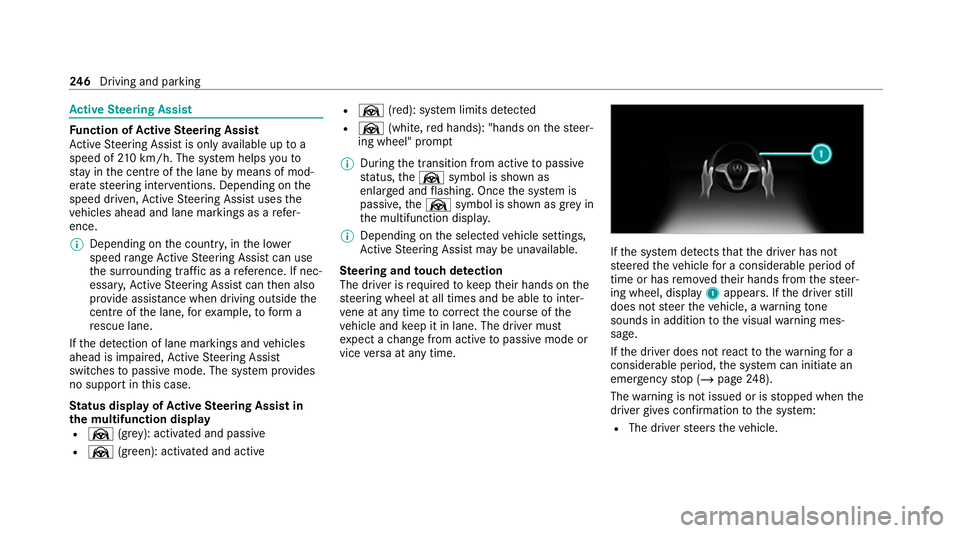
ing wheel, display 1appears. If the driver still
does not steer theve hicle, a warning tone
sounds in addition tothe visual warning mes‐
sage.
If th e driver does not react tothewa rning for a
considerable period, the sy stem can initiate an
emer gency stop (/ page248).
The warning is not issued or is stopped when the
driver gives con firm ation tothe sy stem:
R The driver steers theve hicle. 246
Driving and pa rking
Page 250 of 549
R
Depending on the count ry:th e driver
presses a steering wheel button or operates
To uch Control
If Ac tive Steering Assist de tects that a sy stem
limit has been reached, a visual warning is
issued and a warning tone sounds.
Obser vethe no tes on driving sy stems and your
re sponsibility; you may otherwise failto recog‐
nise dangers (/ page 224).
Sy stem limits
Ac tive Steering Assist has a limited steering tor‐
qu efo r lateral guidance. In some cases, the
st eering inter vention is not su fficient tokeep the
ve hicle in the lane or todrive thro ugh exits.
The sy stem may be impaired or may not function
in thefo llowing ins tances:
R The reis poor visibilit y,e.g. due tosno w,rain,
fo g, heavy spr ay, greatly varying light condi‐
tions or strong shado wsonthe car riag ewa y.
R There is glare, e.g. from oncoming traf fic,
di re ct sunlight or reflections.
R Insuf ficient road illumination. R
The windsc reen is dirty, mis ted up, damaged
or co vered in the vicinity of the camera, e.g.
by ast icke r.
R No, or se veral, unclear lane markings are
present for one lane, or the markings change
qu ickl y,forex ample, in a con stru ction area
or junctions.
R The lane markings are wornaw ay, dark or
co vered up, e.g. bydirt or sno w.
R Ifth e dis tance totheve hicle in front is too
short and thus the lane markings cann otbe
de tected.
R The road is nar rowand winding.
R There are obs tacles on the lane or projecting
out into the lane, such as object mar kers.
The sy stem does not pr ovide assis tance in the
fo llowing conditions:
R On tight bends and when turning.
R When crossing junctions.
R Atroundabouts or tollst ations.
R When towing a trailer.
R When the tyre pressure is too lo w. &
WARNING Risk of accident if Active
St eering Assist unexpectedly stops func‐
tioning
If th e sy stem limits of Active Steering Assist
are reached there is no guarantee that the
sy stem will remain active or will keep the
ve hicle in lane. #
Alw ayske ep your hands on thesteering
wheel and obser vethe tra ffic carefull y. #
Alw aysst eer theve hicle paying atten‐
tion totraf fic conditions. &
WARNING Risk of accident if Active
St eering Assist unexpectedly inter venes
The de tection of lane markings and objects
may malfunction and cause unexpected
st eering inter ventions. #
Steer according totraf fic conditions. Driving and pa
rking 247
Page 293 of 549
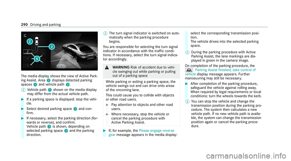
The media display sho
ws the view of Active Park‐
ing Assist. Area 2displa ysdetected pa rking
spaces 4and vehicle path 3.
% Vehicle path 3shown on the media display
may dif fer from the actual vehicle path. #
If a parking space is displa yed: stop theve hi‐
cle. #
Select desired parking space 4and con‐
fi rm. #
If necessar y,select the parking direction (for‐
wa rds or reve rse), and confi rm.
Ve hicle path 3is shown, depending on
selected parking space 4and the parking
direction. %
The turn signal indicator is switched on auto‐
matically when the parking procedure
begins.
Yo u are responsible for selecting the turn signal
indicator in accordance with the traf fic condi‐
tions. If necessar y,select the turn signal indica‐
to r according ly. &
WARNING Risk of accident due tovehi‐
cle swinging out while parking or pulling
out of a parking space
While parking or exiting a parking space, the
ve hicle swings out and can drive onto areas
of the oncoming lane.
This could cause youto collide wi thobjects
or other road users. #
Pay attention toobjects and other road
users. #
Where necessar y,stop theve hicle or
cancel the parking procedure with
Ac tive Parking Assist. #
If,forex ample, thePlease engage reverse
gear message appears in the media display: select
the cor responding transmission posi‐
tion.
The vehicle drives into the selected parking
space.
% During the parking procedure with Active
Pa rking Assist, the lane markings are dis‐
pla yed in green in the camera image.
On completion of the parking procedure, the
Ø Parking Assist finished, take control of
vehicle display message appears. Further
manoeuvring may still be necessar y. #
After completion of the parking procedure,
safeguard theve hicle against rolling away.
When requ ired bylegal requirements or local
conditions: turn the wheels towa rdsth eke rb.
% You can stop theve hicle and change the
transmission position du ring the parking pro‐
cedure. The sy stem then calculates a new
ve hicle path. If no new vehicle path is availa‐
ble, the sy stem can change the transmission
position again or cancel the parking proce‐
dure. 290
Driving and parking