tire pressure MERCEDES-BENZ M-Class 2011 W164 Owner's Guide
[x] Cancel search | Manufacturer: MERCEDES-BENZ, Model Year: 2011, Model line: M-Class, Model: MERCEDES-BENZ M-Class 2011 W164Pages: 372, PDF Size: 16.23 MB
Page 304 of 372
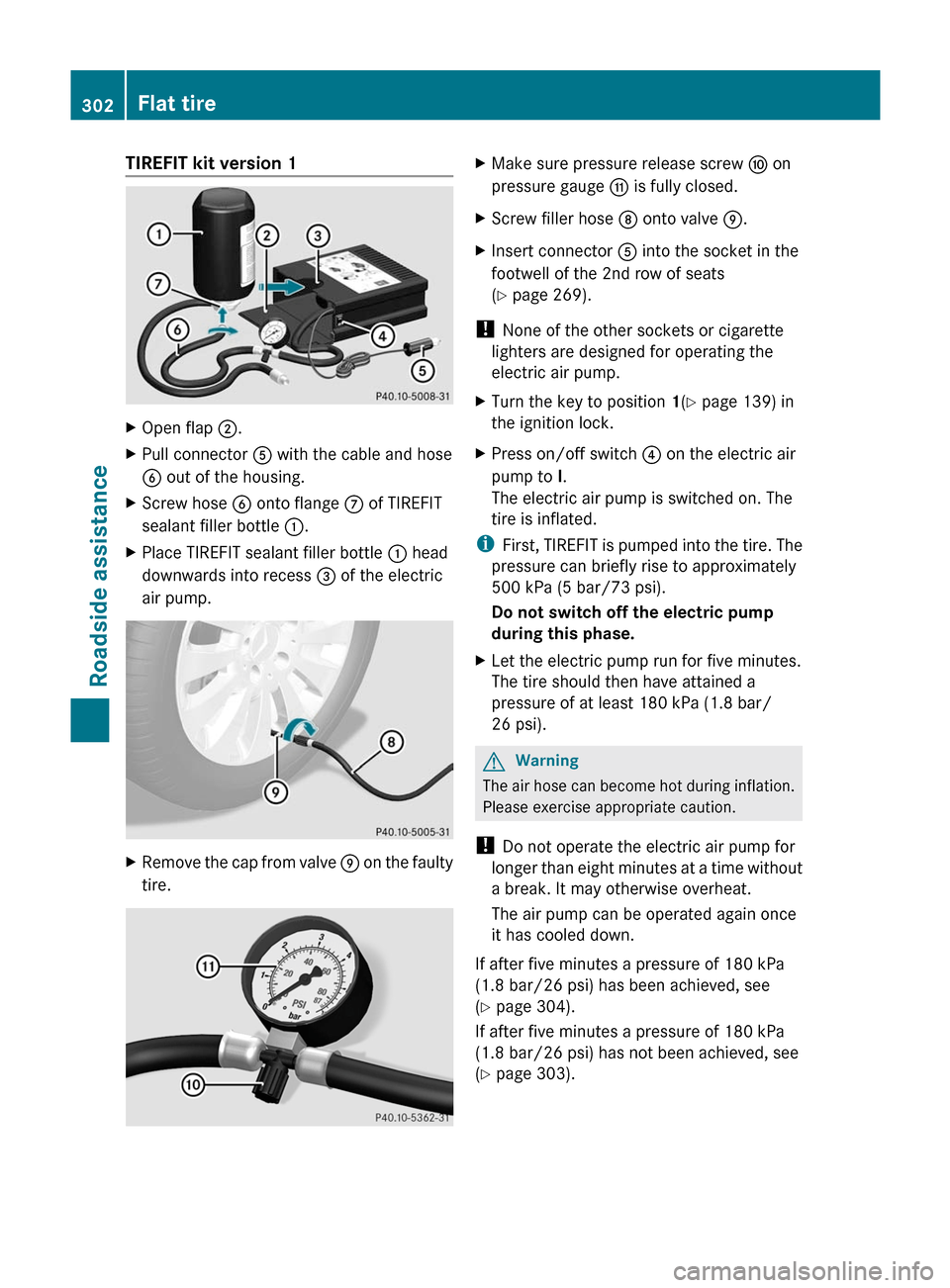
TIREFIT kit version 1XOpen flap ;.XPull connector A with the cable and hose
B out of the housing.
XScrew hose B onto flange C of TIREFIT
sealant filler bottle :.
XPlace TIREFIT sealant filler bottle : head
downwards into recess = of the electric
air pump.
XRemove the cap from valve E on the faulty
tire.
XMake sure pressure release screw F on
pressure gauge G is fully closed.
XScrew filler hose D onto valve E.XInsert connector A into the socket in the
footwell of the 2nd row of seats
(Y page 269).
! None of the other sockets or cigarette
lighters are designed for operating the
electric air pump.
XTurn the key to position 1(Y page 139) in
the ignition lock.
XPress on/off switch ? on the electric air
pump to I.
The electric air pump is switched on. The
tire is inflated.
iFirst, TIREFIT is pumped into the tire. The
pressure can briefly rise to approximately
500 kPa (5 bar/73 psi).
Do not switch off the electric pump
during this phase.
XLet the electric pump run for five minutes.
The tire should then have attained a
pressure of at least 180 kPa (1.8 bar/
26 psi).
GWarning
The air hose can become hot during inflation.
Please exercise appropriate caution.
! Do not operate the electric air pump for
longer than eight minutes at a time without
a break. It may otherwise overheat.
The air pump can be operated again once
it has cooled down.
If after five minutes a pressure of 180 kPa
(1.8 bar/26 psi) has been achieved, see
(Y page 304).
If after five minutes a pressure of 180 kPa
(1.8 bar/26 psi) has not been achieved, see
(Y page 303).
302Flat tireRoadside assistance
BA 164.1 USA, CA Edition B 2011; 1; 2, en-USd2mskotVersion: 3.0.3.52010-04-21T17:25:06+02:00 - Seite 302
Page 305 of 372
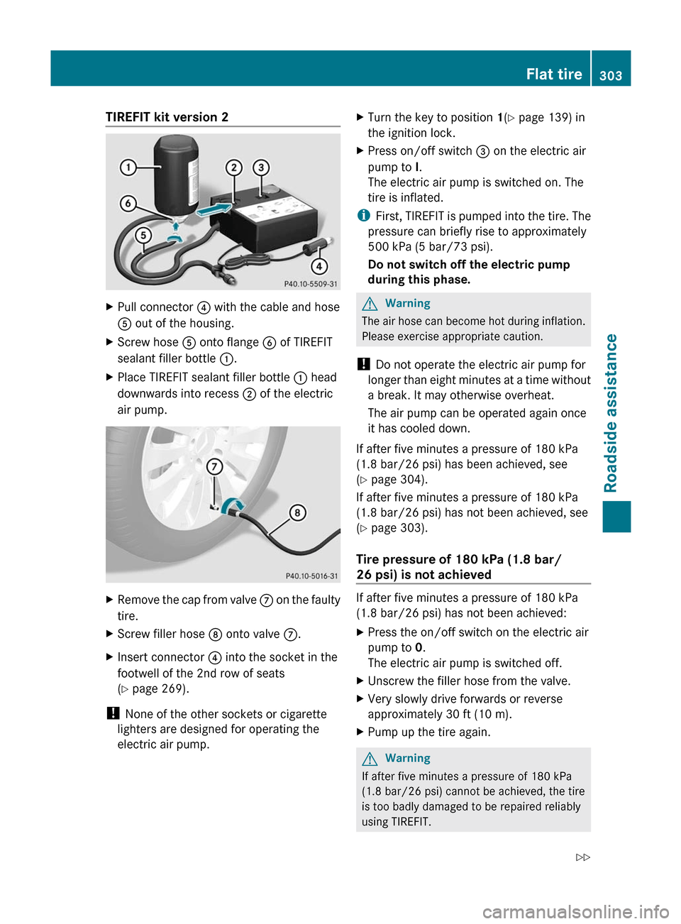
TIREFIT kit version 2XPull connector ? with the cable and hose
A out of the housing.
XScrew hose A onto flange B of TIREFIT
sealant filler bottle :.
XPlace TIREFIT sealant filler bottle : head
downwards into recess ; of the electric
air pump.
XRemove the cap from valve C on the faulty
tire.
XScrew filler hose D onto valve C.XInsert connector ? into the socket in the
footwell of the 2nd row of seats
(Y page 269).
! None of the other sockets or cigarette
lighters are designed for operating the
electric air pump.
XTurn the key to position 1(Y page 139) in
the ignition lock.
XPress on/off switch = on the electric air
pump to I.
The electric air pump is switched on. The
tire is inflated.
iFirst, TIREFIT is pumped into the tire. The
pressure can briefly rise to approximately
500 kPa (5 bar/73 psi).
Do not switch off the electric pump
during this phase.
GWarning
The air hose can become hot during inflation.
Please exercise appropriate caution.
! Do not operate the electric air pump for
longer than eight minutes at a time without
a break. It may otherwise overheat.
The air pump can be operated again once
it has cooled down.
If after five minutes a pressure of 180 kPa
(1.8 bar/26 psi) has been achieved, see
(Y page 304).
If after five minutes a pressure of 180 kPa
(1.8 bar/26 psi) has not been achieved, see
(Y page 303).
Tire pressure of 180 kPa (1.8 bar/
26 psi) is not achieved
If after five minutes a pressure of 180 kPa
(1.8 bar/26 psi) has not been achieved:
XPress the on/off switch on the electric air
pump to 0.
The electric air pump is switched off.
XUnscrew the filler hose from the valve.XVery slowly drive forwards or reverse
approximately 30 ft (10 m).
XPump up the tire again.GWarning
If after five minutes a pressure of 180 kPa
(1.8 bar/26 psi) cannot be achieved, the tire
is too badly damaged to be repaired reliably
using TIREFIT.
Flat tire303Roadside assistanceBA 164.1 USA, CA Edition B 2011; 1; 2, en-USd2mskotVersion: 3.0.3.52010-04-21T17:25:06+02:00 - Seite 303Z
Page 306 of 372
In this case TIREFIT cannot seal the tire
properly.
Do not drive any further.
Contact the nearest authorized Mercedes-
Benz Center for assistance or call roadside
assistance.
Tire pressure of 180 kPa (1.8 bar/
26 psi) is achieved
XPress the on/off switch on the electric air
pump to 0.
The electric air pump is switched off.
XRemove the TIREFIT kit from the wheel.GWarning
The air hose may still be hot. Exercise proper
caution to avoid burning yourself when
detaching the electric air pump.
! After use, excess TIREFIT may run out of
the filler hose. This could cause stains.
Therefore, place the filler hose in the plastic
bag which contained the TIREFIT kit.
XStow the TIREFIT kit and the electric air
pump.
XPull away immediately.GWarning
Do not exceed a vehicle speed of 50 mph
(80 km/h). A TIREFIT repair is not designed to
operate at higher speeds.
The sticker must be attached on the
instrument cluster where it will be easily seen
by the driver.
Vehicle handling characteristics of a TIREFIT
repaired tire may change. Adapt your driving
accordingly.
XStop after driving for approximately ten
minutes and check the tire pressure with
the electric air pump.
GWarning
If tire inflation pressure has fallen below
130 kPa (1.3 bar/26 psi) do not continue to
drive the vehicle.
Park your vehicle safely away from the
roadway and contact the nearest authorized
Mercedes-Benz Center or roadside
assistance.
Have the damaged tire replaced.
XCorrect the tire inflation pressure if it is at
least 130 kPa (1.3 bar/26 psi) (for values
see Tire and Load Information placard on
the driver's side B-pillar or tire inflation
pressure table inside the fuel filler flap).
XTo increase the tire pressure: switch on
the electric air pump.
TIREFIT kit version 1
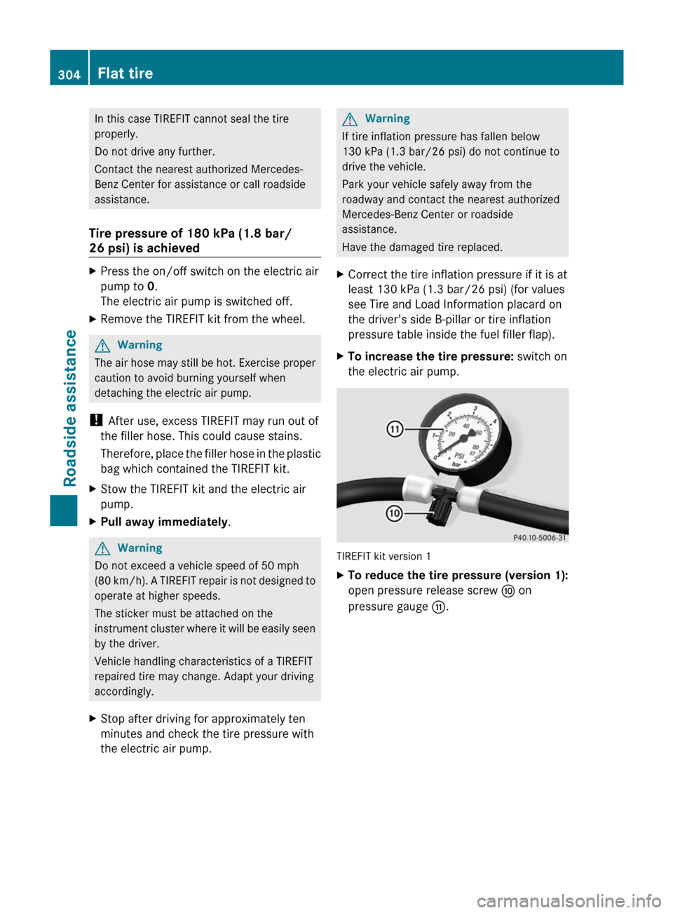
XTo reduce the tire pressure (version 1):
open pressure release screw F on
pressure gauge G.
304Flat tireRoadside assistance
BA 164.1 USA, CA Edition B 2011; 1; 2, en-USd2mskotVersion: 3.0.3.52010-04-21T17:25:06+02:00 - Seite 304
Page 307 of 372
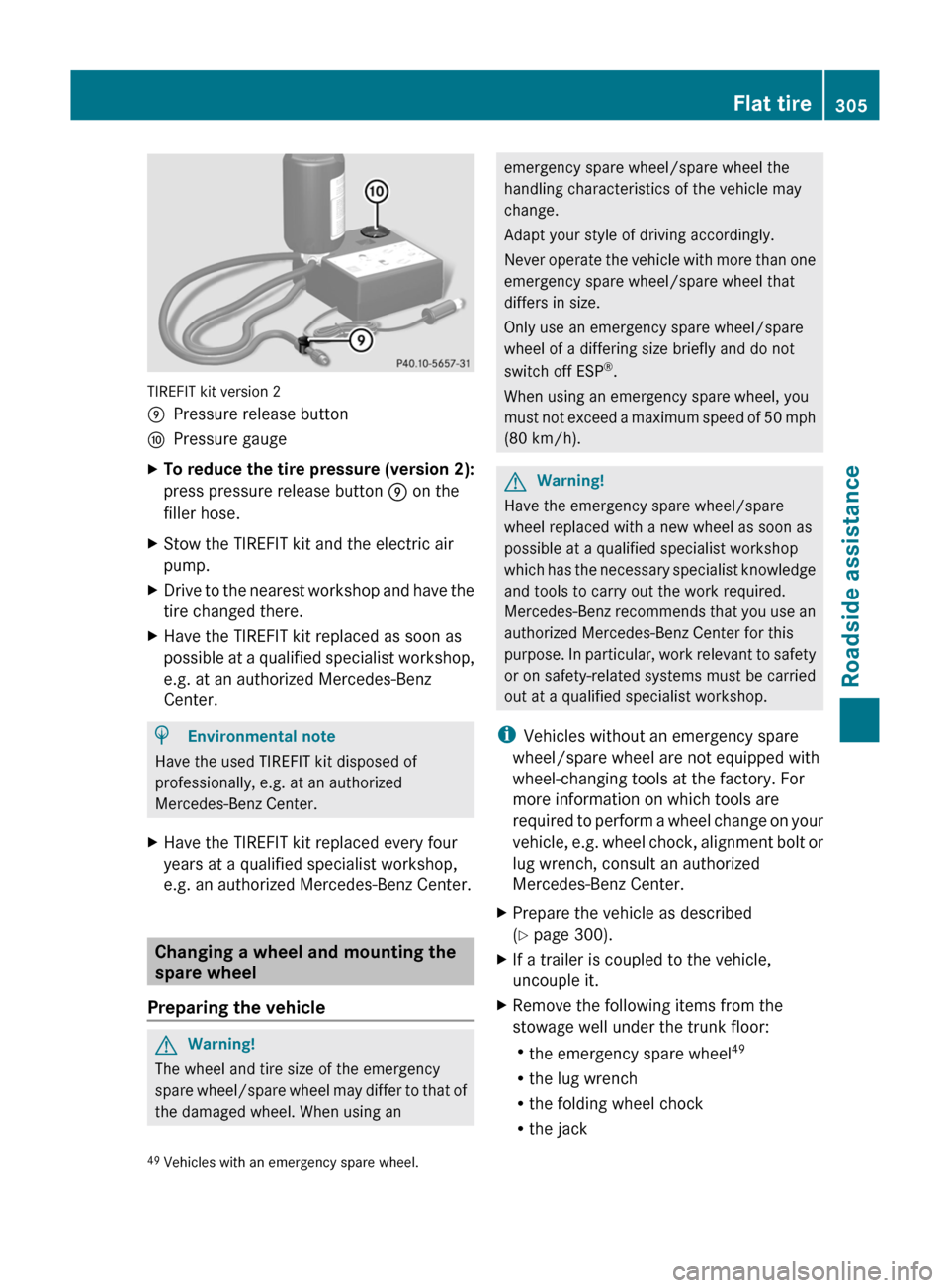
TIREFIT kit version 2
EPressure release buttonFPressure gaugeXTo reduce the tire pressure (version 2):
press pressure release button E on the
filler hose.XStow the TIREFIT kit and the electric air
pump.XDrive to the nearest workshop and have the
tire changed there.XHave the TIREFIT kit replaced as soon as
possible at a qualified specialist workshop,
e.g. at an authorized Mercedes-Benz
Center.HEnvironmental note
Have the used TIREFIT kit disposed of
professionally, e.g. at an authorized
Mercedes-Benz Center.
XHave the TIREFIT kit replaced every four
years at a qualified specialist workshop,
e.g. an authorized Mercedes-Benz Center.
Changing a wheel and mounting the
spare wheel
Preparing the vehicle
GWarning!
The wheel and tire size of the emergency
spare wheel/spare wheel may differ to that of
the damaged wheel. When using an
emergency spare wheel/spare wheel the
handling characteristics of the vehicle may
change.
Adapt your style of driving accordingly.
Never operate the vehicle with more than one
emergency spare wheel/spare wheel that
differs in size.
Only use an emergency spare wheel/spare
wheel of a differing size briefly and do not
switch off ESP ®
.
When using an emergency spare wheel, you
must not exceed a maximum speed of 50 mph
(80 km/h).GWarning!
Have the emergency spare wheel/spare
wheel replaced with a new wheel as soon as
possible at a qualified specialist workshop
which has the necessary specialist knowledge
and tools to carry out the work required.
Mercedes-Benz recommends that you use an
authorized Mercedes-Benz Center for this
purpose. In particular, work relevant to safety
or on safety-related systems must be carried
out at a qualified specialist workshop.
i Vehicles without an emergency spare
wheel/spare wheel are not equipped with
wheel-changing tools at the factory. For
more information on which tools are
required to perform a wheel change on your
vehicle, e.g. wheel chock, alignment bolt or
lug wrench, consult an authorized
Mercedes-Benz Center.
XPrepare the vehicle as described
( Y page 300).XIf a trailer is coupled to the vehicle,
uncouple it.XRemove the following items from the
stowage well under the trunk floor:
R the emergency spare wheel 49
R the lug wrench
R the folding wheel chock
R the jack49Vehicles with an emergency spare wheel.Flat tire305Roadside assistanceBA 164.1 USA, CA Edition B 2011; 1; 2, en-USd2mskotVersion: 3.0.3.52010-04-21T17:25:06+02:00 - Seite 305Z
Page 311 of 372
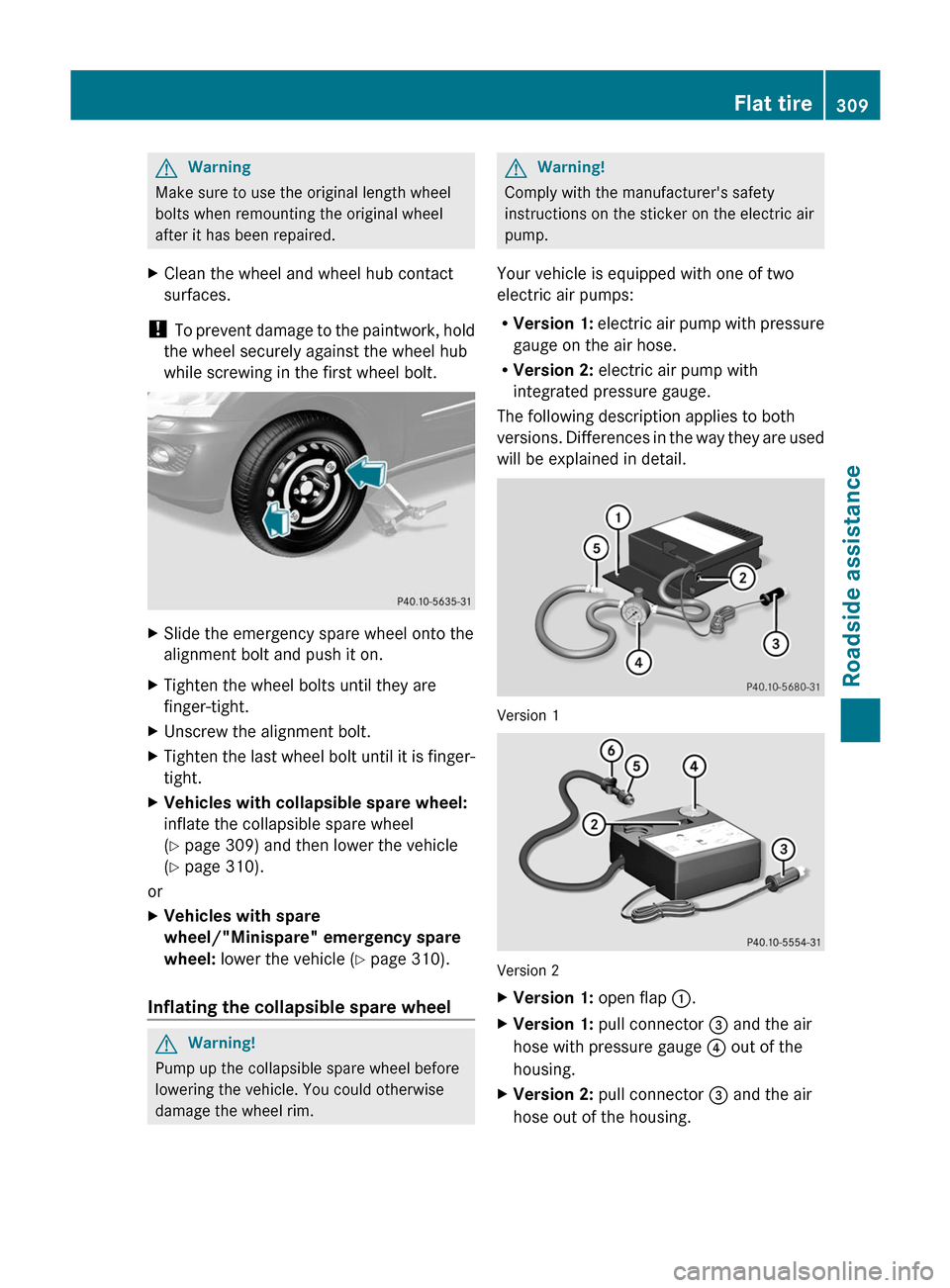
GWarning
Make sure to use the original length wheel
bolts when remounting the original wheel
after it has been repaired.
XClean the wheel and wheel hub contact
surfaces.
! To prevent damage to the paintwork, hold
the wheel securely against the wheel hub
while screwing in the first wheel bolt.
XSlide the emergency spare wheel onto the
alignment bolt and push it on.
XTighten the wheel bolts until they are
finger-tight.
XUnscrew the alignment bolt.XTighten the last wheel bolt until it is finger-
tight.
XVehicles with collapsible spare wheel:
inflate the collapsible spare wheel
(Y page 309) and then lower the vehicle
(Y page 310).
or
XVehicles with spare
wheel/"Minispare" emergency spare
wheel: lower the vehicle (Y page 310).
Inflating the collapsible spare wheel
GWarning!
Pump up the collapsible spare wheel before
lowering the vehicle. You could otherwise
damage the wheel rim.
GWarning!
Comply with the manufacturer's safety
instructions on the sticker on the electric air
pump.
Your vehicle is equipped with one of two
electric air pumps:
RVersion 1: electric air pump with pressure
gauge on the air hose.
RVersion 2: electric air pump with
integrated pressure gauge.
The following description applies to both
versions. Differences in the way they are used
will be explained in detail.
Version 1
Version 2
XVersion 1: open flap :.XVersion 1: pull connector = and the air
hose with pressure gauge ? out of the
housing.
XVersion 2: pull connector = and the air
hose out of the housing.
Flat tire309Roadside assistanceBA 164.1 USA, CA Edition B 2011; 1; 2, en-USd2mskotVersion: 3.0.3.52010-04-21T17:25:06+02:00 - Seite 309Z
Page 312 of 372
XVersion 1: make sure that the pressure
release screw on pressure gauge ? is
closed.XRemove the cap from the valve on the
collapsible spare wheel.XScrew union nut A on the air hose onto the
valve.XMake sure on/off switch ; of the electric
air pump is set to 0.XInsert connector 3 into the socket in the
footwell of the 2nd row of seats
( Y page 269).
!
None of the other sockets or cigarette
lighters are designed for operating the
electric air pump.
XMake sure that the SmartKey is in position
1 (Y page 139) in the ignition lock.XPress on/off switch ; on the electric air
pump to I.
The electric air pump is switched on. The
tire is inflated.GWarning
The air hose and the union nut can become
hot during inflation. Exercise proper caution
to avoid burning yourself when using the
equipment.
! Do not operate the electric air pump for
longer than eight minutes at a time without
a break. It may otherwise overheat.
The air pump can be operated again once
it has cooled down.
XPump the tire to the specified tire pressure.
The specified tire pressure is printed on the
yellow label of the emergency spare wheel.XWhen the specified tire pressure has been
reached, press on/off switch 2 on the
electric air pump to 0.
The electric air pump is switched off.XTurn the SmartKey to position 0 in the
ignition lock.XVersion 1: if the tire pressure is higher than
the specified pressure, open the pressurerelease screw on pressure gauge 4 until
the correct tire pressure has been reached.XVersion 2: if the tire pressure is higher than
the specified pressure, press pressure
release button 6 until the correct tire
pressure has been reached.XUnscrew union nut A on the air hose from
the valve.XScrew the valve cap onto the collapsible
spare wheel valve again.XVersion 1 : stow plug = and the air hose
behind flap :.XVersion 2 : stow plug = and the air hose
in the lower section of the pump housing.XStow the electric air pump in the
designated place in the vehicle.
Lowering the vehicle
GWarning!
Vehicles with spare wheel with collapsible tire
only: Inflate collapsible tire only after the
wheel is properly attached.
Inflate the collapsible tire using the electric
air pump before lowering the vehicle.
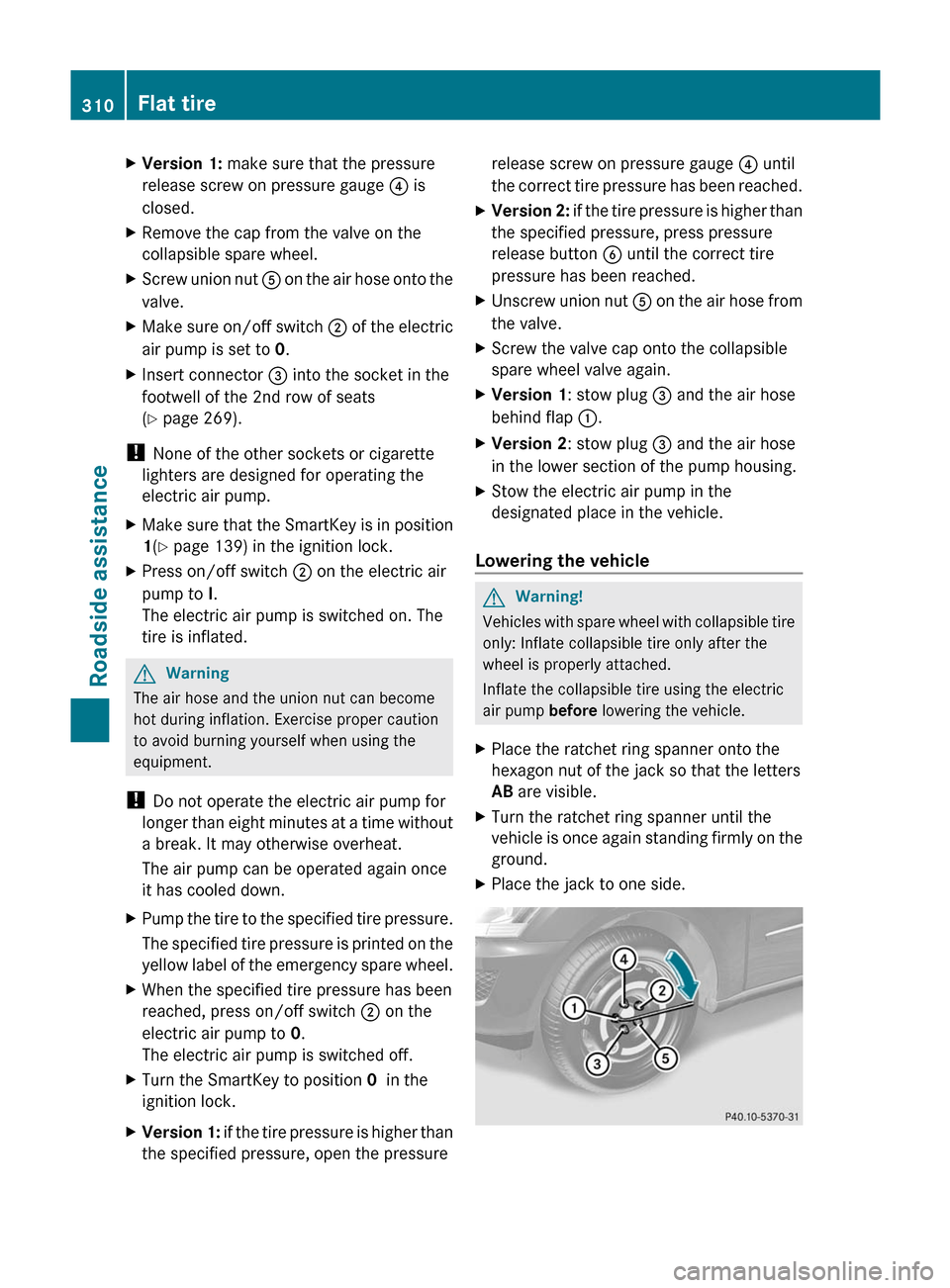
XPlace the ratchet ring spanner onto the
hexagon nut of the jack so that the letters
AB are visible.XTurn the ratchet ring spanner until the
vehicle is once again standing firmly on the
ground.XPlace the jack to one side.310Flat tireRoadside assistance
BA 164.1 USA, CA Edition B 2011; 1; 2, en-USd2mskotVersion: 3.0.3.52010-04-21T17:25:06+02:00 - Seite 310
Page 313 of 372

XTighten the wheel bolts evenly in a
crosswise pattern in the sequence
indicated ( : to A). The tightening torque
must be 110 lb-ft (150 Nm) .GWarning!
Have the tightening torque checked
immediately after a wheel is changed. The
wheels could come loose if they are not
tightened to a torque of 110 lb-ft (150 Nm).
XTurn the jack back to its initial position and
store it together with the rest of the vehicle
tool kit in the cargo compartment.
Vehicles with an emergency spare wheel:
XWrap the faulty wheel in the protective film
included with the emergency spare wheel
and transport the wheel in the cargo
compartment.
or
XDepending on the size of the wheel, you
may also be able to secure the faulty wheel
in the emergency spare wheel well. In this
case, you must remove the stowage tray
from the emergency spare wheel well and
store it securely in the cargo compartment.
Further information on stowing the
collapsible spare wheel ( Y page 299).
i When you are driving with the collapsible
spare wheel mounted, the tire pressure
loss warning system or the tire pressure
monitor cannot function reliably. Only
restart the tire pressure loss warning
system/tire pressure monitor when the
defective wheel has been replaced with a
new wheel.
Vehicles with tire pressure monitor: all
mounted wheels must be equipped with
functioning sensors and the defective
wheel should no longer be in the vehicle.
MOExtended run-flat system
The MOExtended run-flat system allows you
to drive on even if there is a complete loss of
pressure in one or more tires.
The MOExtended run-flat system may only be
used in conjunction with the activated tire
pressure loss warning system or with the
activated tire pressure monitor.
The maximum permissible distance which
can be driven in run-flat mode depends on the
cargo in the vehicle. You can drive 50 miles
(80 km) if the vehicle is partially laden and
18 miles (30 km) if it is fully laden.
The maximum permissible distance which
can be driven in run-flat mode is counted from
the moment the tire pressure loss warning
appears in the multifunction display.
You must not exceed a maximum speed of
50 mph(80 km/h).GWarning!
The handling characteristics of your vehicle
deteriorate in run-flat mode, for example:
R when cornering
R when braking
R when accelerating rapidly
Adapt your driving style accordingly and avoid
sudden changes in direction and sudden
acceleration, as well as driving over obstacles
(i.e. curbs, potholes), and driving off-road.
This is particularly the case when the vehicle
is heavily laden.
The maximum permissible distance that can
be driven in run-flat mode depends to a large
extent on the loads placed on the vehicle. It
can be shorter due to high speeds, a heavy
cargo, sudden changes in direction, the road
surface condition, outside temperature, etc.,
or further if you drive carefully and
conservatively.
Do not continue to drive in run-flat mode if:
R you hear banging noises.
R the vehicle starts to shake.
R you see smoke and smell rubber.
Flat tire311Roadside assistanceBA 164.1 USA, CA Edition B 2011; 1; 2, en-USd2mskotVersion: 3.0.3.52010-04-21T17:25:06+02:00 - Seite 311Z
Page 325 of 372

Vehicle equipment ............................324
Important safety guidelines ............324
Directives to be observed ................325
Maintenance and care of wheels
and tires ............................................. 325
Tire pressures ................................... 326
Maximum tire pressures ..................334
Loading the vehicle ..........................334
Maximum tire load ............................338
Direction of rotation .........................338
Uniform Tire Quality Grading
Standards .......................................... 338
Interchanging the wheels ................340
Tire labeling ....................................... 340
Definitions for tires and loading ......344
Wheel/tire combinations .................347323Tires and wheelsBA 164.1 USA, CA Edition B 2011; 1; 2, en-USd2mskotVersion: 3.0.3.52010-04-21T17:25:06+02:00 - Seite 323
Page 327 of 372

Directives to be observed
R Only mount tires and wheels of the same
type and make.
R Only mount tires of the correct size onto
the wheels.
R After mounting new tires, run them in at
moderate speeds for the first 60 miles
(100 km) as they only reach their full
performance after this distance.
R Do not use tires until they are excessively
worn as the tire traction on wet road
surfaces decreases significantly when the
tread depth is less than 1
/ 8 in (3 mm).
R If the vehicle is heavily laden, check the tire
pressure and adjust it if necessary.
R When parking your vehicle, make sure that
the tires do not get deformed by the curb
or other obstacles. If it is necessary to drive
over curbs, speed humps or similar
elevations, try to do so slowly and at an
obtuse angle. Otherwise, the tires,
particularly the sidewalls, can get
damaged.
Maintenance and care of wheels and
tires
Checking wheels and tires
GWarning
Regularly check the tires for damage.
Damaged tires can cause tire inflation
pressure loss. As a result, you could lose
control of your vehicle.
Worn, old tires can cause accidents. If the tire
tread is worn to minimum tread depth, or if
the tires have sustained damage, replace
them.
R Regularly check the wheels and tires of
your vehicle for damage (e.g. cuts,
punctures, tears, bulges on tires and
deformation or severe corrosion on
wheels), at least once a month, as well as
after driving off-road or on rough roads.
Damaged wheels can cause a loss of tire
pressure.
R Regularly check the tire tread depth and
the condition of the tread across the whole
width of the tire (Y page 325). If necessary,
turn the front wheels to full lock in order to
inspect the inner side of the tire surface.
R All wheels must have a valve cap to protect
the valve against dirt and moisture. Do not
install anything on the valve (such as tire
pressure monitoring systems) other than
the standard valve cap or other valve caps
approved by Mercedes-Benz for your
vehicle.
R Regularly check the pressure of all the tires
including the emergency spare wheel or the
spare wheel, particularly prior to long trips,
and correct the pressure as necessary
( Y page 326).
Service life of tires
The service life of tires depends on the
following factors amongst other things:
R driving style
R tire pressure
R mileage
Replace the tires after six years at the latest,
regardless of wear. This also applies to the
emergency spare wheel/spare wheel.
Tire tread
GWarning
Although the applicable federal motor vehicle
safety laws consider a tire to be worn when
the tread wear indicators (TWI) become
visible at approximately 1
/ 16 in (1.6 mm), we
recommend that you do not allow your tires
to wear down to that level. As tread depth
approaches 1
/ 8 in (3 mm), the adhesion
properties on a wet road are sharply reduced.
Maintenance and care of wheels and tires325Tires and wheelsBA 164.1 USA, CA Edition B 2011; 1; 2, en-USd2mskotVersion: 3.0.3.52010-04-21T17:25:06+02:00 - Seite 325Z
Page 328 of 372

Depending upon the weather and/or road
surface (conditions), the tire traction varies
widely.
Do not use tires until they are excessively
worn as the tire traction on wet road surfaces
decreases significantly when the tread depth
is less than 1
/ 8 in (3 mm).
Tread wear indicators (TWI) are required by
law. Six indicators are positioned over the tire
tread. They are visible as soon as a tread
depth of approximately 1
/ 16 in (1.6 mm) is
reached. If this is the case, the tire is so worn
that it must be replaced.
The recommended tread depth for summer
tires is at least 1
/ 8 in (3 mm). The
recommended tread depth for winter tires is
at least 1
/ 6 in (4 mm).
Bar marking
: for tread wear is integrated
into the tire tread.
Storing tires
Store tires that are not being used in a cool,
dry and preferably dark place. Protect the
tires from contact with oil, grease and fuel.
Cleaning tires
! Do not use a high pressure jet with
circular jet nozzles (concentrated-power
jets) to clean the tires. The high pressure
of the water jet could damage the tires.
Always replace damaged tires.
Tire pressures
Tire pressure information
GWarning
Follow recommended tire inflation pressures.
Do not underinflate tires. Underinflated tires
wear excessively and/or unevenly, adversely
affect handling and fuel economy, and are
more likely to fail from being overheated.
Do not overinflate tires. Overinflated tires can
adversely affect handling and ride comfort,
wear unevenly, increase stopping distance,
and result in sudden deflation (blowout)
because they are more likely to become
punctured or damaged by road debris,
potholes etc.
Do not overload the tires by exceeding the
specified load limit as indicated on the Tire
and Loading Information placard on the
driver's door B-pillar. Overloading the tires
can overheat them, possibly causing a
blowout. Overloading the tires can also result
in handling or steering problems, or brake
failure.
You will find a table of recommended tire
pressures on the Tire and Loading
Information placard on the B-pillar on the
driver's side ( Y page 334). You will find a
table of tire pressures for various operating
conditions on the inside of your vehicle's fuel
filler flap.
To test tire pressure, use a suitable pressure
gauge. The outer appearance of a tire does
not permit any reliable conclusion about the
tire pressure. On vehicles installed with the
electronic tire pressure monitor, the tire
pressure can be checked in the on-board
computer.
GWarning!
Should the tire pressure drop repeatedly:
326Tire pressuresTires and wheels
BA 164.1 USA, CA Edition B 2011; 1; 2, en-USd2mskotVersion: 3.0.3.52010-04-21T17:25:06+02:00 - Seite 326