fuse chart MERCEDES-BENZ M-Class 2011 W164 Owner's Manual
[x] Cancel search | Manufacturer: MERCEDES-BENZ, Model Year: 2011, Model line: M-Class, Model: MERCEDES-BENZ M-Class 2011 W164Pages: 372, PDF Size: 16.23 MB
Page 11 of 372
Exhaust tail pipe (cleaning
instructions) ...................................... 291
Exterior lighting see Lights
Exterior mirrors
Adjusting ....................................... 101
Dipping (automatic) .......................102
Folding in/out (automatically) .......102
Folding in/out (electrically) ...........102
Folding in when locking (on-board
computer) ...................................... 218
Out of position ............................... 102
Setting ........................................... 102
Storing settings (memory
function) ........................................ 103
Storing the parking position ..........103
Exterior view ........................................ 26
F
Filling capacity see Technical data
First-aid kit ......................................... 297
Flat tire Changing a wheel/mounting the
spare wheel ................................... 305
MOExtended run-flat system .........311
Preparing the vehicle .....................300
Raising the vehicle .........................306
TIREFIT kit ...................................... 301
Floormat ............................................. 279
Front fog lamp (display
message) ............................................ 232
Fuel Additives ........................................ 359
Notes ............................................. 358
Premium-grade unleaded gasoline . 358
Refueling ........................................ 151
Specifications ................................ 358
Troubleshooting ............................. 155
Fuel consumption
Current (on-board computer) .........220
Notes ............................................. 160
Fuel filler cap (display message) ..... 236
Fuel filler flap Emergency release ........................153
Opening/closing ............................ 153
Fuel filter (display message) ............ 236
Fuel level
Calling up the range (on-board
computer) ...................................... 220
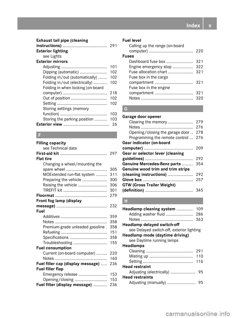
Fuses
Dashboard fuse box .......................321
Engine emergency stop .................322
Fuse allocation chart .....................321
Fuse box in the cargo
compartment ................................. 321
Fuse box in the engine
compartment ................................. 321
Notes ............................................. 320
G
Garage door opener Clearing the memory .....................279
Notes ............................................. 276
Opening/closing the garage door ..278
Programming the remote control ...276
Gear indicator (on-board
computer) .......................................... 209
Gear or selector lever (cleaning
guidelines) ......................................... 292
Genuine Mercedes-Benz parts ......... 354
Genuine wood trim and trim strips
(cleaning instructions) ...................... 292
Glove box ........................................... 257
GTW (Gross Trailer Weight)
(definition) ......................................... 345
H
Headlamp cleaning system .............. 109
Adding washer fluid .......................286
Notes ............................................. 363
Headlamp delayed switch-off
see Delayed switch-off, exterior lighting
Headlamp mode (daytime driving)
see Daytime running lamps
Headlamps
Cleaning ......................................... 291
Misting up ...................................... 110
Setting ........................................... 116
Head restraint
Adjusting (electrically) .....................95
Head restraints
Adjusting (manually) ........................95
Index9BA 164.1 USA, CA Edition B 2011; 1; 2, en-USd2mskotVersion: 3.0.3.52010-04-21T17:25:06+02:00 - Seite 9
Page 91 of 372
! Do not forget that the weather can
change abruptly. Make certain that the
sliding sunroof is closed when you leave the
vehicle. The vehicle electronics can be
damaged if water enters the vehicle
interior.
i Resonance noises can occur in addition
to the usual airflow noises when the sliding
sunroof is open. They are caused by minor
pressure fluctuations in the vehicle interior.
Change the position of the sliding sunroof
or open a side window slightly to reduce or
eliminate these noises.
Operating the sliding sunroof
Opening and closing
i You can still operate the tilt/sliding
sunroof even if you switch off the engine or
remove the SmartKey. This function
remains active for five minutes or until one
of the front doors is opened.
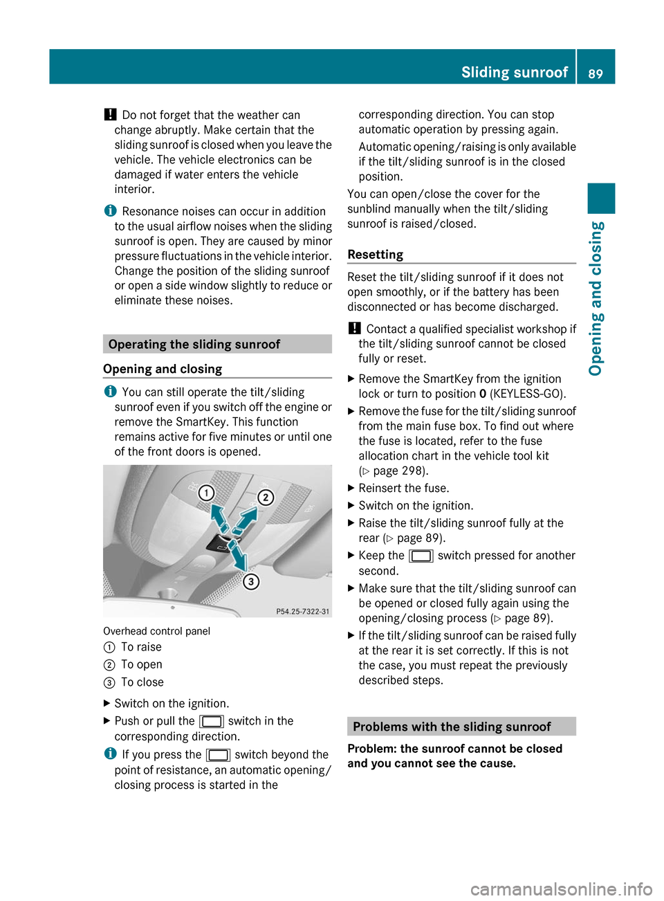
Overhead control panel
:To raise;To open=To closeXSwitch on the ignition.XPush or pull the 2 switch in the
corresponding direction.
i If you press the 2 switch beyond the
point of resistance, an automatic opening/
closing process is started in the
corresponding direction. You can stop
automatic operation by pressing again.
Automatic opening/raising is only available
if the tilt/sliding sunroof is in the closed
position.
You can open/close the cover for the
sunblind manually when the tilt/sliding
sunroof is raised/closed.
Resetting
Reset the tilt/sliding sunroof if it does not
open smoothly, or if the battery has been
disconnected or has become discharged.
! Contact a qualified specialist workshop if
the tilt/sliding sunroof cannot be closed
fully or reset.
XRemove the SmartKey from the ignition
lock or turn to position 0 (KEYLESS-GO).XRemove the fuse for the tilt/sliding sunroof
from the main fuse box. To find out where
the fuse is located, refer to the fuse
allocation chart in the vehicle tool kit
( Y page 298).XReinsert the fuse.XSwitch on the ignition.XRaise the tilt/sliding sunroof fully at the
rear ( Y page 89).XKeep the 2 switch pressed for another
second.XMake sure that the tilt/sliding sunroof can
be opened or closed fully again using the
opening/closing process ( Y page 89).XIf the tilt/sliding sunroof can be raised fully
at the rear it is set correctly. If this is not
the case, you must repeat the previously
described steps.
Problems with the sliding sunroof
Problem: the sunroof cannot be closed
and you cannot see the cause.
Sliding sunroof89Opening and closingBA 164.1 USA, CA Edition B 2011; 1; 2, en-USd2mskotVersion: 3.0.3.52010-04-21T17:25:06+02:00 - Seite 89Z
Page 300 of 372

Vehicle tool kit
Notes
The vehicle tool kit can be found in the
stowage well under the cargo compartment
floor.
i Vehicles without a spare wheel are not
equipped at the factory with the tools
needed to change a wheel, e.g. a jack or lug
wrench. Some tools for changing a wheel
are specific to the vehicle. To obtain tools
approved for your vehicle, visit a qualified
specialist workshop, e.g. an authorized
Mercedes-Benz Center.
Folding the cargo compartment floor up
XPress release handle ; in the direction of
the arrow.XLift cargo compartment floor : up by
release handle ;.XFold out hook = on the underside of the
cargo compartment floor.XAttach hook = to upper seal ? in the
cargo compartment.
Vehicles with a TIREFIT kit
XLift the cargo compartment floor up
( Y page 298).:Towing eye;Alignment bolt=Jack?Fuse allocation chartAElectric air pump 44BTIREFIT kit44CLug wrenchDFolding wheel chockERatchet ring spanner
Vehicles with a "Minispare" emergency
spare wheel/collapsible spare wheel
XLift the cargo compartment floor up
( Y page 298).44
Vehicles with BlueTEC 4MATIC (vehicles for Canada) are only available from the factory with 20" wheels.298Where will I find...?Roadside assistance
BA 164.1 USA, CA Edition B 2011; 1; 2, en-USd2mskotVersion: 3.0.3.52010-04-21T17:25:06+02:00 - Seite 298
Page 301 of 372

Example: vehicles with a collapsible spare wheel
:Electric air pump45;Stowage well=Alignment bolt?Towing eyeALug wrenchXRemove the "Minispare" emergency spare
wheel or the collapsible spare wheel.
Example: vehicles with a collapsible spare wheel
BJackCFolding wheel chockDFuse allocation chartEWheel bolts 46FRatchet ring spanner"
Minispare" emergency spare wheel/
collapsible emergency spare wheel
Removing the "Minispare" emergency
spare wheel/collapsible spare wheel
The emergency spare wheel is under the
cargo compartment floor.
XLift the cargo compartment floor up
( Y page 298).XDepending on the vehicle's equipment,
remove the stowage tray from the
emergency spare wheel.
Example: collapsible spare wheel
XTurn emergency spare wheel retainer :
counter-clockwise and remove it.XRemove the "Minispare" emergency spare
wheel or collapsible spare wheel ;.
For further information on changing a wheel
and mounting the spare wheel, see
( Y page 305).
Stowing a used collapsible spare wheel
Take the following steps to stow a used
collapsible spare wheel. It will otherwise not
fit in the spare wheel well. Mercedes-Benz
recommends that you have this work carried
out at a qualified specialist workshop, e.g. an
authorized Mercedes-Benz Center.
! Only place the collapsible spare wheel in
the vehicle when it is dry. Otherwise,
moisture may get into the vehicle.
45 Only vehicles with a "Minispare" emergency spare wheel or a collapsible spare wheel.
46 Only vehicles with a "Minispare" emergency spare wheel.Where will I find...?299Roadside assistanceBA 164.1 USA, CA Edition B 2011; 1; 2, en-USd2mskotVersion: 3.0.3.52010-04-21T17:25:06+02:00 - Seite 299Z
Page 322 of 372
As soon as the vehicle has been loaded: XPrevent the vehicle from rolling away by
applying the parking brake.XShift the automatic transmission to
position P.XTurn the SmartKey to position 0 in the
ignition lock and remove the SmartKey.XSecure the vehicle.
! Only lash the vehicle down by the wheels
or wheel rims, not by parts of the vehicle
such as axle or steering components.
Otherwise, the vehicle could be damaged.
Notes on 4MATIC vehicles
! Vehicles with 4MATIC must not be towed
with either the front or the rear axle raised,
as doing so will damage the transmission.
If the vehicle's transmission, front, or rear
axle is damaged, have the vehicle transported
on a truck or trailer.
In the event of damage to the electrical
system
If the battery is defective, the automatic
transmission will be locked in position P. To
shift the automatic transmission to position
N , you must provide power to the vehicle's
electrical system in the same way as when
jump-starting ( Y page 315).
Have the vehicle transported on a transporter
or trailer.
Recovering a vehicle that has become
stuck
! Pull away smoothly, slowly, and in a
straight line when pulling out a vehicle that
has become stuck. Excessive tractive
power could damage the vehicles.
If the drive wheels have become stuck in
loose or muddy ground, pull the vehicle out
with extreme caution, particularly if it is
laden.
Never attempt to recover a stuck vehicle with
a trailer attached.
Pull out the vehicle backwards, if possible
using the tracks it made when it became
stuck.
Fuses
Important safety guidelines
The fuses in your vehicle serve to close down
faulty circuits. If a fuse blows, all the
components on the circuit and their functions
will fail.
GWarning
Only use fuses approved by Mercedes-Benz
with the specified amperage for the system in
question and do not attempt to repair or
bridge a blown fuse. Using other than
approved fuses or using repaired or bridged
fuses may cause an overload leading to a fire,
and/or cause damage to electrical
components and/or systems. Have the cause
determined and remedied by an authorized
Mercedes-Benz Center.
Blown fuses must be replaced with fuses of
the same rating, which you can recognize by
the color and value. The fuse ratings are listed
in the fuse allocation chart. An authorized
Mercedes-Benz Center will be happy to
advise you.
i If a fuse has blown, visit a breakdown
service or an authorized Mercedes-Benz
Center.
If the newly inserted fuse also blows, have the
cause traced and rectified at a qualified
specialist workshop, e.g. an authorized
Mercedes-Benz Center.
! Only use fuses that have been approved
for Mercedes-Benz vehicles and which
have the correct fuse rating for the system
concerned. Otherwise, components or
systems could be damaged.
320FusesRoadside assistance
BA 164.1 USA, CA Edition B 2011; 1; 2, en-USd2mskotVersion: 3.0.3.52010-04-21T17:25:06+02:00 - Seite 320
Page 323 of 372
Before changing a fuseXPark the vehicle and apply the parking
brake.XSwitch off all electrical consumers.XRemove the key from the ignition lock.
The fuses are located in various fuse boxes:
R fuse box on the front-passenger side of the
dashboard
R fuse box in the engine compartment on the
right-hand side of the vehicle, when viewed
in the direction of travel
R fuse box in the cargo compartment on the
right-hand side of the vehicle, when viewed
in the direction of travel
The fuse allocation chart is located in the
vehicle tool kit ( Y page 298) in the stowage
compartment under the trunk floor.
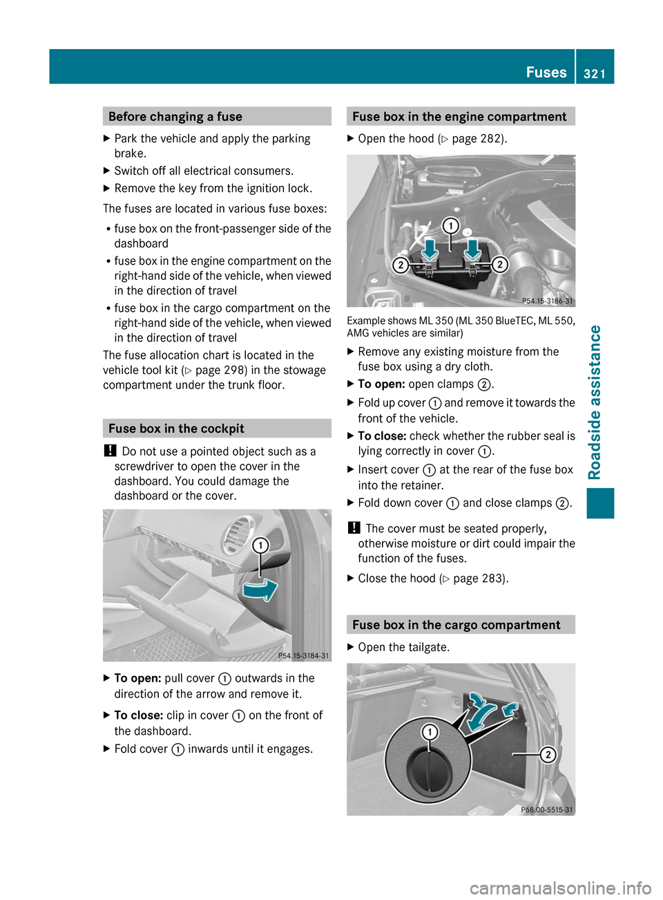
Fuse box in the cockpit
! Do not use a pointed object such as a
screwdriver to open the cover in the
dashboard. You could damage the
dashboard or the cover.
XTo open: pull cover : outwards in the
direction of the arrow and remove it.XTo close: clip in cover : on the front of
the dashboard.XFold cover : inwards until it engages.Fuse box in the engine compartmentXOpen the hood ( Y page 282).
Example shows ML 350 (ML 350 BlueTEC, ML 550,
AMG vehicles are similar)
XRemove any existing moisture from the
fuse box using a dry cloth.XTo open: open clamps ;.XFold up cover : and remove it towards the
front of the vehicle.XTo close: check whether the rubber seal is
lying correctly in cover :.XInsert cover : at the rear of the fuse box
into the retainer.XFold down cover : and close clamps ;.
!
The cover must be seated properly,
otherwise moisture or dirt could impair the
function of the fuses.
XClose the hood ( Y page 283).
Fuse box in the cargo compartment
XOpen the tailgate.Fuses321Roadside assistanceBA 164.1 USA, CA Edition B 2011; 1; 2, en-USd2mskotVersion: 3.0.3.52010-04-21T17:25:06+02:00 - Seite 321Z
Page 324 of 372
XTo open: insert a suitable object, e.g. a
coin, into the slot of release buttons : on
the cover.XTurn release buttons : 90° in the
direction of the arrow.XOpen cover ; downwards.
Engine emergency off
If the engine cannot be switched off as
described, observe the following procedure:
XTake the fuse allocation chart out of the
vehicle tool kit ( Y page 298).XOpen the fuse box in the engine
compartment ( Y page 321).XRemove fuse 120. The installation location
of the fuse is described in the fuse
allocation chart.322FusesRoadside assistance
BA 164.1 USA, CA Edition B 2011; 1; 2, en-USd2mskotVersion: 3.0.3.52010-04-21T17:25:06+02:00 - Seite 322