tow bar MERCEDES-BENZ M-Class 2011 W164 Owner's Manual
[x] Cancel search | Manufacturer: MERCEDES-BENZ, Model Year: 2011, Model line: M-Class, Model: MERCEDES-BENZ M-Class 2011 W164Pages: 372, PDF Size: 16.23 MB
Page 16 of 372
Belt force limiters ............................ 57
Cleaning ......................................... 293
Correct usage .................................. 54
Emergency Tensioning Devices ........ 57
Fastening ......................................... 55
Important safety guidelines .............53
Releasing ......................................... 56
Safety guidelines ............................. 37
Switching belt adjustment on/off
(on-board computer) ......................218
Warning lamp ................................. 248
Warning lamp (function) ................... 57
Seat heating
Indicator lamp (Malfunction) ............98
Seats
Adjusting (electrically) .....................94
Adjusting the 4-way lumbar
support ............................................ 97
Adjusting the head restraint ............95
Cleaning the cover .........................292
Correct driver's seat position ........... 92
Important safety instructions ...........93
Multicontour seat ............................ 97
Storing settings (memory
function) ........................................ 103
Switching seat heating on/off .........97
Switching the seat ventilation on/
off .................................................... 98
Seat ventilation
Indicator lamp (Malfunction) ............99
Securing hooks .................................. 260
Sensors (cleaning instructions) ....... 291
Service indicator see Service interval display
Service interval display .................... 287
Displaying a service message (on-
board computer) ............................ 287
Service products
AdBlue ®
special additives ..............360
Brake fluid ..................................... 362
Coolant (engine) ............................ 362
Engine oil ....................................... 361
Filling capacity ............................... 357
Fuel ................................................ 358
Important safety notes ..................356
Notes ............................................. 356Refrigerant (air-conditioning
system) .......................................... 362
Washer fluid ................................... 363
Settings
Factory (on-board computer) .........213
On-board computer .......................213
Shift ranges ....................................... 148
Side impact air bag ............................. 40
Side marker lamp (display
message) ............................................ 232
Side windows Convenience closing feature ............86
Convenience opening feature ..........86
Important safety information ...........84
Opening/closing .............................. 85
Resetting ......................................... 87
Troubleshooting ............................... 87
Sliding sunroof
Important safety information ...........88
Troubleshooting ............................... 89
see Tilt/sliding sunroof
SmartKey
Changing the battery .......................76
Changing the programming .............75
Checking the battery .......................76
Important safety notes ....................72
Malfunction ...................................... 77
Snow chains ...................................... 165
Socket ................................................ 268
Dashboard ..................................... 268
Front-passenger footwell ...............268
Luggage compartment ...................269
Rear compartment .........................269
SOS
see mbrace
Spare wheel
Notes/data .................................... 352
Storage location ............................ 299
Stowing .......................................... 299
see Emergency spare wheel
Speedometer
Additional speedometer (on-
board computer) ............................ 208
Segments ...................................... 205
Setting the unit (on-board
computer) ...................................... 21414IndexBA 164.1 USA, CA Edition B 2011; 1; 2, en-USd2mskotVersion: 3.0.3.52010-04-21T17:25:06+02:00 - Seite 14
Page 19 of 372
Total load limit (definition) .............347
Traction ......................................... 339
Traction (definition) .......................346
Tread wear ..................................... 339
TWR (permissible trailer drawbar
noseweight) (definition) .................347
Uniform tire quality classification
standards (definition) .....................344
Unladen weight (definition) ............345
Wear indicator (definition) .............347
Wheel rim (definition) ....................345
Tires and wheels (important safety
information) ....................................... 324
Top Tether ............................................ 62
Towing Important safety guidelines ...........317
Towing a trailer
Driving tips .................................... 198
Towing away
Installing the towing eye ................318
Removing the towing eye ...............319
Trailer
Coupling up ................................... 198
Decoupling ..................................... 200
Display message ............................ 230
Power supply ................................. 201
Towing ........................................... 199
Trailer loads and drawbar
noseweights ...................................... 200
Trailer towing .................................... 147
Blind Spot Assist ............................ 191
ESP ®
................................................ 68
PARKTRONIC ................................. 186
Transfer case ..................................... 151
Transmission position display ......... 145
Transmission positions .................... 146
Traveling uphill Brow of hill ..................................... 171
Driving downhill ............................. 171
Maximum gradient-climbing
capability ....................................... 170
Trip computer (on-board
computer) .......................................... 219
Trip odometer Calling up ....................................... 208
Resetting (on-board computer) ......220Trunk
Automatic opening ..................... 82, 83
Turn signal (display message) ......... 230
Turn signals ....................................... 109
TWR (permissible trailer drawbar
noseweight) (definition) ................... 347
Type plate see Vehicle identification plate
U
Unlocking Emergency unlocking .......................80
From inside the vehicle (central
unlocking button) ............................. 79
V
Vanity mirror Sun visor ........................................ 266
Vehicle
Data acquisition ............................... 23
Emergency release ..........................80
Equipment ....................................... 19
Exterior view .................................... 26
Individual settings (on-board
computer) ...................................... 213
Loading .......................................... 334
Lowering ........................................ 310
Maintenance .................................... 20
Parking up ..................................... 159
Raising ........................................... 306
Reporting problems .........................22
Towing away .................................. 317
Tow-starting ................................... 317
Transporting .................................. 319
Vehicle data
see Technical data
Vehicle identification number
see VIN
Vehicle identification plate .............. 355
Vehicle tool kit .................................. 298
Video (DVD) ........................................ 212
Video DVD (on-board computer) ...... 212
VIN ...................................................... 355
Index17BA 164.1 USA, CA Edition B 2011; 1; 2, en-USd2mskotVersion: 3.0.3.52010-04-21T17:25:06+02:00 - Seite 17
Page 190 of 372

GWarning!
The rear view camera is only an aid and may
display obstacles
R from a distorted perspective
R inaccurately
R may not display obstacles at all
The rear view camera does not relieve you of
the responsibility to be cautious. Take care
and pay careful attention. The rear view
camera may not show objects which are
R very close to the rear bumper
R under the rear bumper
R above the tailgate handle
You are responsible for safety at all times and
must continue to pay attention to the
immediate surroundings when parking and
maneuvering. This includes the area behind,
in front of, and beside the vehicle. Otherwise
you could endanger yourself and/or others.
GWarning!
The rear view camera either will not function
or will not function to its full capability if
R the tailgate is open
R it is raining very hard, snowing or foggy
R it is night or you are parking/maneuvering
your vehicle in an area where it is very dark
R the camera is exposed to a very bright white
light
R the immediate surroundings are
illuminated with fluorescent light (the
display may flicker)
R there is a sudden change in temperature,
e.g. if you drive into a heated garage from
the cold (lens condensation)
R the camera lens is dirty or covered
R the rear of your vehicle is damaged
In this case, have the position and setting
of the camera checked by a qualified
specialist workshop. Mercedes-Benz
recommends that you contact a Mercedes-
Benz Center for this purpose.
Do not use the rear view camera in these
situations. Otherwise you could injure
yourself or others and/or damage property
including your vehicle while parking/
maneuvering.
Activating the rear view cameraXMake sure that the key is in position 2 in
the ignition lock.XMake sure that the "rear view camera"
function is selected in COMAND APS; see
the separate operating instructions for
COMAND APS.XEngage reverse gear.
The area behind the vehicle is shown in the
COMAND APS display with guide lines.
Guide lines in the COMAND APS display
GWarning!
Use of rear view camera can be dangerous if
you are color-blind or have impaired color
vision.
Only use rear view camera if you can see and
distinguish all colored guidelines shown by
rear view camera on the COMAND system
display.
GWarning
Please note that objects that do not touch the
ground may appear to be further away than
they actually are, for example:
R the bumper of a vehicle parked behind you
R the trailer drawbar
R the ball coupling of a trailer tow hitch
R the rear end of a truck
R a slanted post
In such cases, you should not use the guide
lines to judge the distance. You may misjudge
the distance, which increases the risk of
impacting the objects.
Even if the object you approach is directly on
the ground, do not approach the object any
closer than the red guide line.
188Driving systemsDriving and parking
BA 164.1 USA, CA Edition B 2011; 1; 2, en-USd2mskotVersion: 3.0.3.52010-04-21T17:25:06+02:00 - Seite 188
Page 200 of 372
Message in the multifunction display
Diff. Lock System Overheated -
Wait briefly.
The differential lock system has overheated
and briefly disengaged.XContinue driving.
The differential locks cool off and are soon
available once again.
Towing a trailer
Notes on towing a trailer
Important safety instructions
GWarning!
Failure to use proper equipment and driving
technique can result in a loss of vehicle
control when towing a trailer.
Improper towing or failure to follow the
instructions in this manual can result in
vehicle damage and/or serious personal
injury. Follow the guidelines below carefully
to assure safe trailer operation.
Contact an authorized Mercedes-Benz Center
should you require an explanation of
information contained in this manual.
General information
R Only install an approved trailer coupling on
your vehicle.
Further information on availability and on
installation is available from any authorized
Mercedes-Benz Center.
R The bumpers of your vehicle are not
suitable for installing detachable trailer
couplings.
R Do not install hired trailer couplings or
other detachable trailer couplings on the
bumpers of your vehicle.
R To reduce the risk of damage to the ball
coupling, remove it from the ball coupling
recess when not in use.
Coupling up a trailerGWarning!
Vehicles with air suspension program: While
you are coupling or decoupling a trailer, make
sure nobody locks or unlocks the vehicle and/
or opens or closes doors or the tailgate.
The vehicle’s level could change and you
could endanger yourself and/or others as a
result.
Make sure that you do not operate the ADS
switch or the vehicle level control system
when coupling/decoupling the trailer.
Observe the maximum permissible trailer
dimensions (width and length).
Most federal states and all Canadian
provinces require by law:
R safety chains between the towing vehicle
and the trailer. The chains should be cross-
wound under the trailer drawbar. They must
be fastened to the vehicle's trailer
coupling, not to the bumper or the axle.
Allow for enough play in the chains to
facilitate turning tight corners.
R a separate brake system for certain types
of trailer.
R a safety switch for braked trailers. Check
the specific legal requirements applicable
to your federal state.
If the trailer detaches from the towing
vehicle, the safety switch applies the
trailer's brakes.
! Do not connect the trailer's brake system
(if featured) to the hydraulic brake system
of the towing vehicle, as the latter is
equipped with an anti-lock brake system.
Doing so will result in a loss of function of
the brake systems of both the vehicle and
the trailer.
i The vehicle's wiring harness features a
line to the brake indicator lamp.
198Towing a trailerDriving and parking
BA 164.1 USA, CA Edition B 2011; 1; 2, en-USd2mskotVersion: 3.0.3.52010-04-21T17:25:06+02:00 - Seite 198
Page 202 of 372
ROn long and steep gradients that are
difficult to drive down in shift range 1,
switch to the off-road drive program.
R When driving downhill, shift to a lower gear
to utilize the engine's braking effect.
Avoid continuous brake application as this
may overheat the vehicle brakes and, if
installed, the trailer brakes.
R If the coolant temperature increases
dramatically while the air-conditioning
system is switched on, switch off the air-
conditioning system.
Coolant heat can additionally be dissipated
by opening the windows and by setting the
blower fan and the interior temperature to
maximum.
R When overtaking, pay particular attention
to the extended length of your vehicle/
trailer combination.
Due to the length of your vehicle/trailer
combination, you will have to travel an
additional distance beyond the vehicle you
are overtaking before returning to the
previous lane.
Decoupling a trailer
GWarning!
Vehicles with air suspension program: While
you are coupling or decoupling a trailer, make
sure nobody locks or unlocks the vehicle and/
or opens or closes doors or the tailgate.
The vehicle’s level could change and you
could endanger yourself and/or others as a
result.
Make sure that you do not operate the ADS
switch or the vehicle level control system
when coupling/decoupling the trailer.
XMake sure that the automatic transmission
is set to position P.XApply the vehicle's parking brake.XStart the engine.XClose all doors and the tailgate.XApply the trailer's parking brake.GWarning!
Vehicles with air suspension program: As
soon as you disconnect the electrical
connection between the trailer and the
vehicle, the vehicle will lower. To help avoid
personal injury, make sure no one is near the
wheel housing or underneath the vehicle
before the electrical connection is
disconnected.
When you decouple the trailer, the vehicle is
temporarily raised because the springs are
relieved of load. Be especially careful during
this process, as you could otherwise injure
yourself and/or others. Make sure that any
persons remaining in the vehicle do not press
the switches for vehicle level control or the
ADS.
XDetach the trailer cable and decouple the
trailer.XDetach the trailer cable and decouple the
trailer.XSwitch off the engine.
Permissible trailer load and drawbar
noseweight
Weight specifications
The Gross Trailer Weight (GTW) is the
combined weight of the trailer together with
the cargo and equipment loaded on the
trailer. Permissible gross weight:
R Vehicles with 4MATIC: 7200 lb (3265 kg)
R Vehicles without 4MATIC: 4630 lb
(2100 kg)
The permissible Trailer drawbar Weight
Rating (TWR) is the maximum weight
permitted on the trailer drawbar:
R Vehicles with 4MATIC: 576 lb (261 kg) limit
for Mercedes-Benz-approved trailer
couplings
R Vehicles without 4MATIC: 370 lb (168 kg)
limit for Mercedes-Benz-approved trailer
couplings
200Towing a trailerDriving and parking
BA 164.1 USA, CA Edition B 2011; 1; 2, en-USd2mskotVersion: 3.0.3.52010-04-21T17:25:06+02:00 - Seite 200
Page 203 of 372
Loading a trailer
RWhen loading a trailer, please note that
neither the permissible gross trailer weight
nor the permissible Gross Vehicle Weight
Rating (GVWR) may be exceeded. The
permissible Gross Vehicle Weight Rating
(GVWR) is specified on the type plate
located on the B-pillar on the driver's side
of your vehicle.
You can find the maximum permissible
values on the type plates of your vehicle
and the trailer. Always observe the lowest
respective value when determining the
maximum weight with which you can load
the vehicle and the trailer.
R The drawbar noseweight acting on the ball
coupling has to be added to the rear axle
weight in order to prevent the permissible
Gross Axle Weight Rating (GAWR) from
being exceeded. The permissible Gross
Vehicle Weight Rating (GVWR) is specified
on the type plate located on the B-pillar on
the driver's side of your vehicle.
i Mercedes-Benz recommends loading the
trailer so that the drawbar noseweight
remains between 8% and 15% of the
permissible gross trailer weight.
i The weight of additional accessories,
passengers, and cargo reduces the
permissible trailer load and drawbar
noseweight for your vehicle.
Checking the vehicle and trailer weight
R To check that the weights of the towing
vehicle and the trailer comply with the
maximum permissible values, have the
vehicle/trailer combination (including the
driver, passengers, and cargo with a fully
laden trailer) weighed on a calibrated
weighbridge.
R Check the permissible axle weight of the
front and rear axle, the Gross Trailer Weight
(GTW), and the drawbar noseweight.
Check the permissible axle weight of the
front and rear axle, the Gross Trailer Weight
(GTW), and the drawbar noseweight.
Trailer power supply
The trailer power socket of your vehicle is
designed for connecting the 7-pin connector
supplied as part of the Mercedes-Benz-
approved trailer coupling.
i Depending on your trailer, you may need
an adapter to connect your trailer to the
vehicle.
Further information is available from any
authorized Mercedes-Benz Center.
Towing a trailer201Driving and parkingBA 164.1 USA, CA Edition B 2011; 1; 2, en-USd2mskotVersion: 3.0.3.52010-04-21T17:25:06+02:00 - Seite 201Z
Page 267 of 372
Roof carrier
Important safety guidelinesGWarning!
Only use carriers when the basic carrier bars
have been completely mounted. The left and
right roof rails are only stabilized by means of
the basic carrier bars mounted.
Follow the manufacturer’s installation
instructions. Otherwise, an improperly
attached carrier or its load could become
detached from the vehicle.
Do not exceed the maximum roof load of
220 lb (100 kg).
Take into consideration that when the roof is
loaded, the handling characteristics are
different from those when operating the
vehicle without the roof loaded.
! Mercedes-Benz recommends that you
only use roof carriers that have been tested
and approved for Mercedes-Benz vehicles.
This helps to prevent damage to the
vehicle.
Position the cargo on the roof rack in such
a way that the vehicle will not sustain
damage even when it is in motion.
Depending on the vehicle equipment,
ensure that when the roof carrier is
installed you can:
R raise the tilt/sliding sunroof fully
R open the tailgate fully
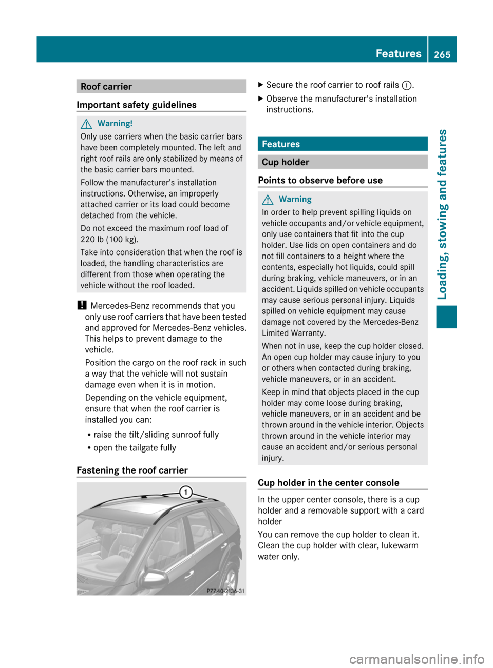
Fastening the roof carrier
XSecure the roof carrier to roof rails :.XObserve the manufacturer's installation
instructions.
Features
Cup holder
Points to observe before use
GWarning
In order to help prevent spilling liquids on
vehicle occupants and/or vehicle equipment,
only use containers that fit into the cup
holder. Use lids on open containers and do
not fill containers to a height where the
contents, especially hot liquids, could spill
during braking, vehicle maneuvers, or in an
accident. Liquids spilled on vehicle occupants
may cause serious personal injury. Liquids
spilled on vehicle equipment may cause
damage not covered by the Mercedes-Benz
Limited Warranty.
When not in use, keep the cup holder closed.
An open cup holder may cause injury to you
or others when contacted during braking,
vehicle maneuvers, or in an accident.
Keep in mind that objects placed in the cup
holder may come loose during braking,
vehicle maneuvers, or in an accident and be
thrown around in the vehicle interior. Objects
thrown around in the vehicle interior may
cause an accident and/or serious personal
injury.
Cup holder in the center console
In the upper center console, there is a cup
holder and a removable support with a card
holder
You can remove the cup holder to clean it.
Clean the cup holder with clear, lukewarm
water only.
Features265Loading, stowing and featuresBA 164.1 USA, CA Edition B 2011; 1; 2, en-USd2mskotVersion: 3.0.3.52010-04-21T17:25:06+02:00 - Seite 265Z
Page 302 of 372
XRemove the valve extractor from the
vehicle tool kit.XUnscrew the valve cap from the valve.XUnscrew the valve insert from the valve and
release the air.
i Fully deflating the tire can take a few
minutes.
XScrew the valve insert back into the valve.XScrew the valve cap back on.XPlace the valve extractor back into the
vehicle tool kit.XStow the collapsible spare wheel in the
emergency spare wheel well under the
cargo compartment and fasten in place.
Flat tire
Preparing the vehicle
Your vehicle may be equipped with:
R a TIREFIT kit 47
R a "Minispare" emergency spare wheel
R a collapsible spare wheel
R the MOExtended run-flat
system( Y page 311)
i Vehicle preparation is not necessary on
vehicles with the MOExtended run-flat
system.
i Vehicles featuring the MOExtended run-
flat system are not equipped with the
TIREFIT kit at the factory. It is therefore
recommended that you additionally equip
your vehicle with the TIREFIT kit if you
mount tires that do not feature run-flat
properties, e.g. winter tires. You can obtain
a TIREFIT kit from an authorized Mercedes-
Benz Center, for example.
XMake sure that highway level is
selected 48
(Y page 181).XStop the vehicle as far away as possible
from traffic on solid, non-slippery and level
ground.XSwitch on the hazard warning lamps.XFirmly depress the parking brake.XBring the front wheels into the straight-
ahead position.XMove the DIRECT SELECT lever to P.XSwitch off the engine.XVehicles without KEYLESS-GO: remove
the key from the ignition lock.XVehicles with KEYLESS-GO: open the
driver's door.
The on-board electronics have status 0,
which is the same as the key having been
removed.XVehicles with KEYLESS-GO: remove the
Start/Stop button from the ignition lock
( Y page 139).XAll occupants must get out of the vehicle.
Make sure that they are not endangered as
they get out of the vehicle.XMake sure that no one is near the danger
area whilst a wheel is being changed.
Anyone who is not directly assisting in the
wheel change should, for example, stand
behind the barrier.XGet out of the vehicle. Pay attention to
traffic conditions when doing so.XClose the driver's door.
i Only operate the electric air pump using
the socket in the footwell of the 2nd row of
seats ( Y page 269), even if the ignition is
turned off.
An emergency cut-off ensures that the on-
board voltage does not drop too low. If the
on-board voltage is too low, power to the
sockets is automatically cut-off. This
47 Canada only.
48 Vehicles with air suspension.300Flat tireRoadside assistance
BA 164.1 USA, CA Edition B 2011; 1; 2, en-USd2mskotVersion: 3.0.3.52010-04-21T17:25:06+02:00 - Seite 300
Page 306 of 372
In this case TIREFIT cannot seal the tire
properly.
Do not drive any further.
Contact the nearest authorized Mercedes-
Benz Center for assistance or call roadside
assistance.
Tire pressure of 180 kPa (1.8 bar/
26 psi) is achieved
XPress the on/off switch on the electric air
pump to 0.
The electric air pump is switched off.
XRemove the TIREFIT kit from the wheel.GWarning
The air hose may still be hot. Exercise proper
caution to avoid burning yourself when
detaching the electric air pump.
! After use, excess TIREFIT may run out of
the filler hose. This could cause stains.
Therefore, place the filler hose in the plastic
bag which contained the TIREFIT kit.
XStow the TIREFIT kit and the electric air
pump.
XPull away immediately.GWarning
Do not exceed a vehicle speed of 50 mph
(80 km/h). A TIREFIT repair is not designed to
operate at higher speeds.
The sticker must be attached on the
instrument cluster where it will be easily seen
by the driver.
Vehicle handling characteristics of a TIREFIT
repaired tire may change. Adapt your driving
accordingly.
XStop after driving for approximately ten
minutes and check the tire pressure with
the electric air pump.
GWarning
If tire inflation pressure has fallen below
130 kPa (1.3 bar/26 psi) do not continue to
drive the vehicle.
Park your vehicle safely away from the
roadway and contact the nearest authorized
Mercedes-Benz Center or roadside
assistance.
Have the damaged tire replaced.
XCorrect the tire inflation pressure if it is at
least 130 kPa (1.3 bar/26 psi) (for values
see Tire and Load Information placard on
the driver's side B-pillar or tire inflation
pressure table inside the fuel filler flap).
XTo increase the tire pressure: switch on
the electric air pump.
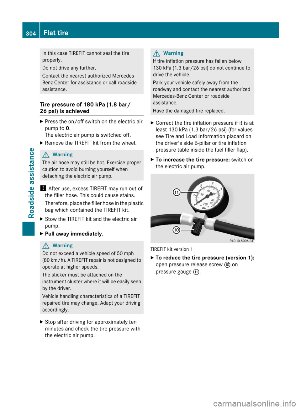
TIREFIT kit version 1
XTo reduce the tire pressure (version 1):
open pressure release screw F on
pressure gauge G.
304Flat tireRoadside assistance
BA 164.1 USA, CA Edition B 2011; 1; 2, en-USd2mskotVersion: 3.0.3.52010-04-21T17:25:06+02:00 - Seite 304
Page 319 of 372

XFirst remove the jumper cable from earth point B and negative terminal ?, then from
positive terminal ; and positive terminal =, each time disconnecting from the battery on
your own vehicle first.XHave the battery checked at a qualified specialist workshop, e.g. an authorized Mercedes-
Benz Center.Towing and tow-starting
Important safety guidelines
GWarning
Hybrid vehicles: ensure that you read the
"HYBRID" supplement. You may otherwise fail
to recognize dangers.
GWarning
If you tow the vehicle, you must use a rigid
towing bar if:
R the engine will not run.
R there is a malfunction in the brake system.
R there is a malfunction in the power supply
or the vehicle's electrical system.
With the engine not running, there is no power
assistance for the brake and steering
systems. You will then need considerably
more force to steer and to brake and the
brake pedal travel will be longer. If necessary,
depress the brake pedal with maximum force.
Before towing away, make sure that the
steering can be moved and is not locked.
If you tow or tow-start another vehicle, its
weight must not exceed the maximum
permissible gross vehicle weight of your
vehicle.
It is better to have the vehicle transported
than to have it towed.
! You may only tow the vehicle a maximum
distance of 30 miles (50 km). A towing
speed of 30 mph (50 km/h) must not be
exceeded.
For towing distances over 30 miles
(50 km), the vehicle must loaded onto a
transporter.
! Only secure the tow rope or tow bar at the
towing eyes. Otherwise, the vehicle could
be damaged.
! Do not use the towing eye for recovery,
as this could damage the vehicle. If in
doubt, recover the vehicle with a crane.
! Drive slowly and smoothly when towing.
Excessive tractive power could otherwise
damage the vehicles.
! Do not tow with sling-type equipment.
This could damage the vehicle.
! When towing vehicles with KEYLESS-GO,
use the key instead of the Start/Stop
button. Otherwise, the automatic
transmission may shift to position P when
the driver's or front-passenger door are
opened, which could lead to damage to the
transmission.
! Vehicles with differential locks: make
sure that the differential locks are in
automatic mode. When towing, the
differential locks must not be switched on
by hand. This could otherwise damage the
transmission.
! Vehicles with automatic transmission
must not be started by tow-starting. This
could otherwise damage the transmission.
! Vehicles with 4MATIC must not be towed
with the front or rear axle raised. This could
otherwise damage the transmission.
If the vehicle has suffered transmission
damage, have it carried away on a transporter
or trailer.
The automatic transmission must be in
position N when the vehicle is being towed.Towing and tow-starting317Roadside assistanceBA 164.1 USA, CA Edition B 2011; 1; 2, en-USd2mskotVersion: 3.0.3.52010-04-21T17:25:06+02:00 - Seite 317Z