MERCEDES-BENZ METRIS 2016 MY16 Operator’s Manual
Manufacturer: MERCEDES-BENZ, Model Year: 2016, Model line: METRIS, Model: MERCEDES-BENZ METRIS 2016Pages: 310, PDF Size: 7.28 MB
Page 161 of 310
The rear view camera may show obstacles in
perspectival distortion, incorrectly or not at all.
The rear view camera cannot display all objects
located very near and/or under the rear
bumper. It does not warn you ofacollision, per-
sons or objects.
Under the following circumstances, the rear
view camera will not function, or will function in
al imited manner:
Rif the tailgate or rear door is open
Rif it is raining very heavily or snowing, or it is
foggy.
Rat night or in very dark places
Rif the camera is exposed to very bright light.
White lines may appear in the camera image.
Rif the area is lit by fluorescent light or LED
lighting. The camera image may flicker.
Rif the camera lens fogs up, e.g. when driving
into aheated garage in winter, causing arapid
change in temperature.
Rif the camera lens is dirty or obstructed.
Observe the notes on cleaning (Ypage 257).
Rif the rear of the vehicle is damaged. In this
case, have the camera position and setting
checked at aqualified specialist workshop.
Do not use the rear view camera in these situa-
tions. You could otherwise injure others or dam-
age object sand the vehicle while parking and
maneuvering.
The field of vision and other functions of the rear
view camera may be restricted due to additional accessories on the rear of the vehicle (e.g.
license plate holder, rear-mounted bicycle
rack).
Guide lines are alwayss hown at road level. In
trailer mode, the guide lines are shown at the
level of the trailer coupling.
If you change wheel size, make sure they corre-
spond to the correctw heel size category
(
Ypage 267). If the category is changed without
recoding the control units in the vehicle, the rear
view camera cannot be precisely calibrated. The
guide lines at road level or at the level of the
trailer tow hitch will not be displayed correctly.
In vehicles with atailgate, the rear view camera
is protected from raindrops and dust by means
of aflap. When the rear view camera is activa-
ted, this flap opens.
The flap closes again when:
Ryou have finished the maneuvering process
Ryou switch off the engine For technical reasons, the flap may remain open
briefly after the rear view camera has been
deactivated.
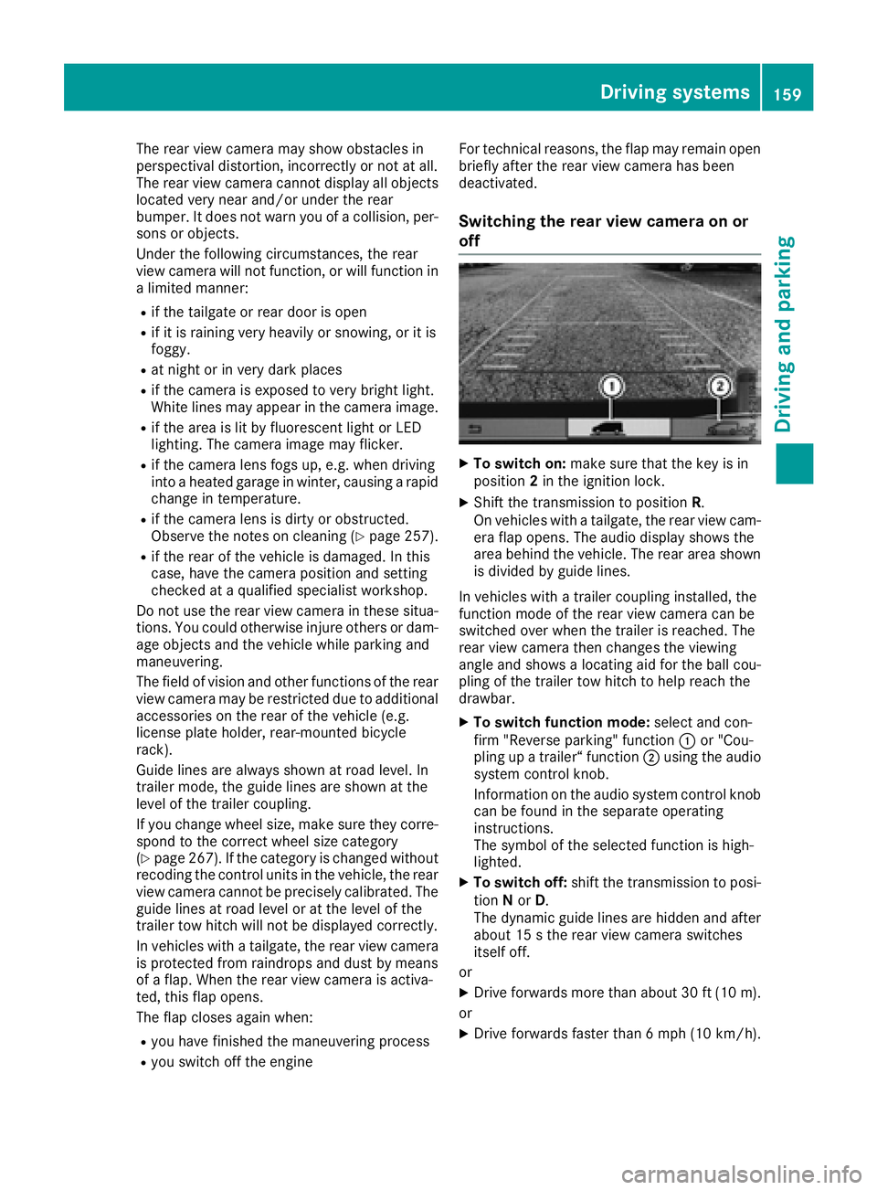
Switching the rear view camera on or
off
XTo switch on: make sure that the key is in
position 2in the ignition lock.
XShift the transmission to position R.
On vehicles with atailgate, the rear view cam-
era flap opens. The audio display shows the
area behind the vehicle. The rear area shown
is divided by guide lines.
In vehicles with atrailer coupling installed, the
function mode of the rear view camera can be
switched over when the trailer is reached. The
rear view camera then changes the viewing
angle and shows alocating aid for the ball cou-
pling of the trailer tow hitch to help reach the
drawbar.
XTo switch function mode: select and con-
firm "Reverse parking" function :or "Cou-
pling up atrailer“ function ;using the audio
system control knob.
Information on the audio system control knob
can be found in the separate operating
instructions.
The symbol of the selected function is high-
lighted.
XTo switch off: shift the transmission to posi-
tion Nor D.
The dynamic guide lines are hidden and after
about 15 sthe rear view camera switches
itself off.
or
XDrive forwards more than about 30 ft (10 m).
or
XDrive forwards faster than 6mph (10 km/h) .
Driving system s159
Driving an dparking
Z
Page 162 of 310
or
XShift the automatic transmission toP.
In vehicles with Active Parking Assist,t he rear
view camera remains switched on after the ini-
tial shift to reverse gear for the whole duration of
active parking assistance. You can find informa-
tion on active parking assistance under "Active
Parking Assist“(
Ypage 154).
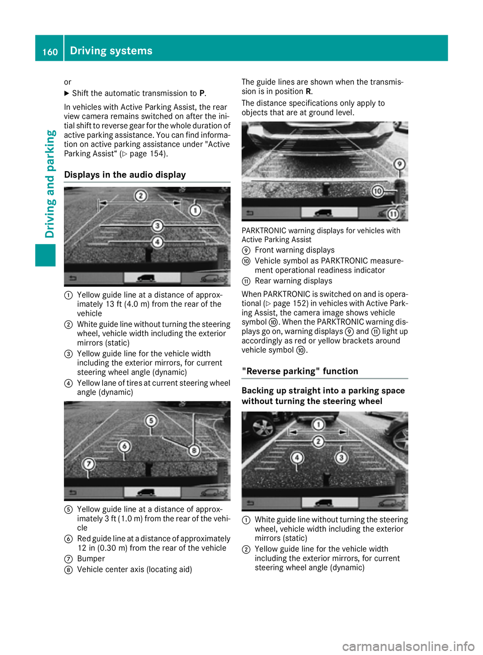
Displays in the audio display
:Yellow guide line at adistance of approx-
imately 13 ft (4.0 m) from the rear of the
vehicle
;White guide line without turnin gthe steering
wheel, vehicle width including the exterior
mirrors (static)
=Yellow guide line for the vehicle width
including the exterior mirrors, for current
steering wheel angle (dynamic)
?Yellow lane of tires at current steering wheel
angle (dynamic)
AYellow guide line at adistance of approx-
imately 3ft(1.0 m) from the rear of the vehi-
cle
BRed guide line at adistance of approximately
12 in (0.30 m) from the rear of the vehicle
CBumper
DVehicle center axis (locating aid) The guide lines are shown when the transmis-
sion is in position
R.
The distance specification sonly apply to
object sthat are at ground level.
PARKTRONIC warning displaysf or vehicles with
Active Parking Assist
E
Frontw arning displays
FVehicle symbol as PARKTRONIC measure-
ment operational readiness indicator
GRear warning displays
When PARKTRONIC is switched on and is opera- tional (
Ypage 152) in vehicles with Active Park-
ing Assist,t he camera image shows vehicle
symbol F.When the PARKTRONIC warning dis-
plays go on, warning displays Eand Glight up
accordingly as red or yellow bracket saround
vehicle symbol F.
"Reverse parking" function
Backing up straight into aparking space
without turning the steering wheel
:White guide line without turnin gthe steering
wheel, vehicle width including the exterior
mirrors (static)
;Yellow guide line for the vehicle width
including the exterior mirrors, for current
steering wheel angle (dynamic)
160Driving systems
Driving and parking
Page 163 of 310
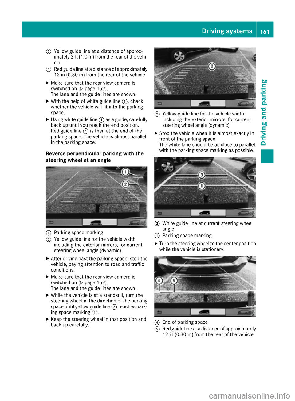
=Yellow guide line atadistance of approx-
imately 3ft(1.0m)f rom the rear of the vehi-
cle
?Red guide line at adistance of approximately
12 in (0.30 m) from the rear of the vehicle
XMake sure that the rear view camer ais
switched on (Ypage 159).
The lane and the guide lines are shown.
XWith the help of white guide line :,check
whether the vehicle will fit int othe parking
space.
XUsingw hite guide line :asag uide, carefully
back up until you reach the end position.
Red guide line ?is the natthe end of the
parking space. The vehicle is almost parallel
in the parking space.
Reverse perpendicular parking with the
steering wheel at an angle
:Parking space marking
;Yellow guide line for the vehicle width
including the exterior mirrors, for current
steeringw heel angle (dynamic)
XAfter drivingp ast the parking space, sto pthe
vehicle, paying attention to road and traffic
conditions.
XMake sure that the rear view camer ais
switched on (Ypage 159).
The lane and the guide lines are shown.
XWhile the vehicle is at astandstill, turn the
steeringw heel in the direction of the parking
space until yellow guide line ;reaches park-
ing space marking :.
XKeep the steeringw heel in that position and
back up carefully.
;Yellow guide line for the vehicle width
including the exterior mirrors, for current
steeringw heel angle (dynamic)
XStop the vehicle when it is almost exactly in
frontofthe parking space.
The white lane should be as close to parallel
with the parking space marking as possible.
=Whiteg uide line at current steeringw heel
angle
:Parking space marking
XTurn the steeringw heel to the center position
while the vehicle is stationary.
?En dofp arking space
ARed guide line at adistance of approximately
12 in (0.30 m) from the rear of the vehicle
Driving systems161
Driving and parking
Z
Page 164 of 310
XBack up carefully untilyouhav ereached the
end position.
Re dg uide lineAis then aligne dwitht he
marking at the end of parking space ?.The
vehicle is almost parallel in the parking space.
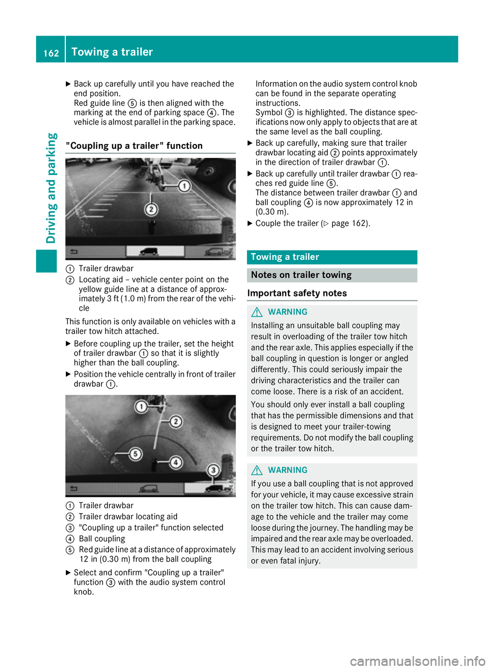
"Coupling up atrailer" function
:Trailer drawbar
;Locating ai d–vehicle center point on the
yellow guid elineatad istance of approx-
imately 3ft(1.0m) from the rearofthe vehi-
cle
Thi sfun ctio niso nlya vailable on vehicles with a
trailer tow hitch attached.
XBefore coupling up the trailer, sett he height
of trailer drawbar :so thatiti ssligh tly
highe rthant he ball coupling.
XPositio nthe vehicl ecentrally in front of trailer
drawbar :.
:Trailer drawbar
;Trailer drawbar locating aid
="Coupling up atrailer" functio nselect ed
?Ballcoupling
ARe dg uide line at adistance of approximately
12 in (0.3 0m)fromt he ball coupling
XSelect and confirm "Coupling up atrailer"
function =with the audi osystemc ontrol
knob. Informatio
nonthe audi osystemc ontrolknob
can be found in the separate operating
instructions.
Symbol =is highlighted. The distance spec-
ifications now onl yapply to objects thata reat
the same level as the ball coupling.
XBac kupcarefully, making sure thatt railer
drawbar locating aid ;points approximately
in the direction of trailer drawbar :.
XBackupcarefull yuntiltrailer drawbar :rea-
che sred guid eline A.
The distance between trailer drawbar :and
ball coupling ?is now approximately 12 in
(0.30 m).
XCouplethe trailer (Ypage 162).
Towin gatrailer
Note sont railer towing
Important safety notes
GWARNING
Installing an unsuitable ball coupling may
resul tino verloading of the trailer tow hitch
and the rea raxle. This applie sespecially if the
ball coupling in questio nislon gerora ngled
differently. This could seriously impair the
drivin gcharacteristics and the trailer can
come loose .Ther eisar iskofana ccident.
Yo us houl donlye verinstal laballc oupling
thath asthe permissibl edimensions and that
is designe dtomeety ou rtrailer-towing
requirements .Donot modify the ball coupling
or the trailer tow hitch.
GWARNING
If yo uuseab allc oupling thati snot approved
for your vehicle, it mayc ause excessive strain
on the trailer tow hitch. This can cause dam-
ag etot he vehicl eand the trailer mayc ome
loose durin gthe journey .The handling may be
impaired an dthe rea raxlem aybe overloaded.
Thi sm aylead to an accident involvin gserious
or eve nfatal injury.
162Towin gatrailer
Driving an dparking
Page 165 of 310
Therefore notethe following:
ROnly installaball coupling that is approved
for your vehicle.
RBefore the journey, make sure that the ball
coupling is correctly installed and secured.
To do this, observe the operating instruc-
tions of the ball coupling manufacturer.
RDo not make any modification stothe ball
coupling or the trailer tow hitch.
You must observe the operating instructions
of the trailer tow hitch or ball coupling manu-
facturer.
GWARNING
If the ball coupling is not correctly installed
and secured, it could come loose while driving and endanger other road users. There is arisk
of an accident and injury.
Install and secure the ball coupling as descri-
bed in the ball coupling manufacturer's instal-
lation instructions .Make sure that the ball
coupling is correctly installed and secured
before every journey.
GWARNING
When the vehicle/trailer combination begins
to lurch, you could lose control of it. The vehi- cle/trailer combination could even rollover.
There is arisk of an accident.
On no account should you attempt to
straighten up the vehicle/trailer combination
by increasingt he speed. Reduce vehicle
speed and do not countersteer. Apply the
brake as necessary.
You can attach carrier systems such as bicycle
racks or load-bearing implements on the ball
coupling. The maximum noseweight of 165 lb
(75 kg) applies when using carrier systems on
the ball coupling.
Always observe the operating instructions pro-
vided by the manufacturers of the trailer cou-
pling and the ball coupling.
Couple and decouple the trailer carefully. When backing up the towing vehicle, make sure
nobody is standin gbetween the vehicle and the
trailer. At
railer which is incorrectly coupled to the tow-
ing vehicle could break away.Ac orrectly cou-
pled trailer must be positioned horizontally
behind the towing vehicle.
Ensure that the following weights are not excee-
ded:
Rthe permissible noseweight
Rthe permissible trailer load
Rthe permissible rear axle load of the towing
vehicle
Rthe maximum permissible gross vehicle
weight of both the towing vehicle and the
trailer
Rthe maximum permissible gross weight of
vehicle/trailer combination
The applicable permissible values that may not
be exceeded can be found:
Rin your vehicle documents
Ron the type plates for the trailer tow hitch
Ron the type plates for the trailer
Ron the vehicle identification plate
(Ypage 294).
Where the values differ, the lowest is valid.
You will find the values approved by the manu-
facturer on the vehicle identification plates and
those for the towing vehicle in the "Technical
data" section (
Ypage 305).
Your vehicle behaves differently with atrailer
than without one.
The vehicle/trailer combination:
Ris heavier
Ris restricted in its acceleration and gradient-
climbing capability
Rhas an increased braking distance
Ris more susceptible to stron gcrosswinds
Rrequires more sensitiv esteering
Rhas alarger turnin gcircle
This may impair the handling characteristics.
When towing atrailer, alwaysa djust your speed
to suit the road and weather conditions. Drive
carefully. Maint ainasafe
distance.
If you require any further explanation regarding
the information contained in the Operating
Instructions, please contact aMercedes-Benz
Commercial Van Center.
Towing atrailer163
Driving and parking
Z
Page 166 of 310
General notes
RObserve the legally prescribed maximum
speed for vehicle/trailer combinations in the
relevant country, state or Canadianprovince.
Before setting off, check the vehicle docu-
ments of the you rtraile rtof ind out the per-
missible maximu mspeed.
This reduces the risk of accidents.
RInstall only an approved traile rcoupling on
you rvehicle .Only use aballc oupling that is
approved for you rvehicle and Sprinter trailer
tow hitch. More information on the availabil-
ity, mounting and installation of the trailer
electrics is available at any qualified specialist
workshop.
RThe traile rcoupling is one of the most impor-
tant vehicle parts with regard to road safety.
Observe the notes on operation, care and
maintenance of the traile rtow hitch (see the
manufacturer's operating instructions).
RThe bumpers of you rvehicle are not suitable
for installing detachable traile rcouplings.
RDo not attach rented traile rtow hitches or
other detachable traile rtow hitches to the
bumper.
RMinimize the risk of damage to the bal lcou-
pling. If you do not require the bal lcoupling,
remove it from the bal lcoupling recess.
You wil lfind weight information under "Techni-
cal Data" (
Ypage 305).
The heigh tofthe bal lneck changes according to
the loadont he vehicle.Ifthis is case, use a
traile rwith aheight-adjustabl etraile rdrawbar.
Driving tips
The maximu mpermissibl espeed for vehicle/
traile rcombinatio ndepends on the type of
trailer. Before setting off, check the vehicle
documents of the you rtraile rtof ind out the
permissibl emaximu mspeed.O bserve the
legally prescribed maximu mspeed for vehicle/
traile rcombinations in the relevant country,
state or Canadianp rovince.
When towing atrailer, you rvehicle's handling
characteristics wil lbedifferent in comparison to
when driving withou tatraile rand it wil lcon-
sume more fuel.
On long and steep downhill gradients, select a
lower gear.
iThis also appliesifc ruise control is activa-
ted. This enables you to utilize the engine's braking
effect and you do not need to brake so heavily to
keep the correct speed.w
hich protects the
brake system and prevents the brakes from
overheating and wearing too quickly. If you need to brake additionally, to not depress the brake
pedalc onstantly, but periodically.
Observe the notes on ESP
®traile rstabilization
(Ypage 65).
Driving tips
If the traile rbegins to swing from side to side:
XDo not accelerate.
XDo not counter-steer.
XBrake if necessary.
iYou can reduce the risk of the traile rswing-
ing and rocking by retrofitting anti-roll bars or traile rstability programs. More information is
available from you rauthorized Sprinter
Dealer.
RMaintain agreater distance than you would
when driving withou ttowing atrailer.
RAvoid sudden braking. Apply the brakes gen-
tly at first to allow the traile rbrake to overrun.
Then, increase the brake force quickly.
RThe figures for the gradient climbing capabil-
ities from astandstill refer to sea level.W hen
driving in mountainou sareas, note that the
powe routpu toft he engine, and with it its
gradient climbing capability, decrease with
increasing altitude.
164Towing atrailer
Driving and parking
Page 167 of 310
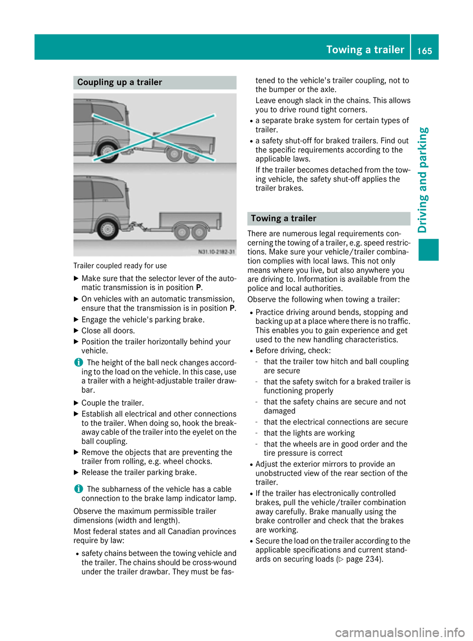
Coupling upatrailer
Trailer coupled read yfor use
XMakes ure that th eselecto rleveroft heauto-
matic transmission is in position P.
XOn vehicleswithana utomatic transmission,
ensure that th etransmission is in position P.
XEngage thevehicle's parking brake.
XClose all doors.
XPositio nthe trailer horizontally behindy our
vehicle.
iThe height of th eball neck changes accord-
ing to th eload on th evehicle .Inthisc ase, use
at railer withah eight-adjustable trailer draw-
bar.
XCouple th etrailer.
XEstablish all electrical and other connections
to th etrailer.W hen doings o, hook thebreak-
away cabl eofthetrailer int othe eyelet on the
ball coupling.
XRemove th eobject sthata re preventin gthe
trailer from rolling ,e.g.w heel chocks.
XRelease th etrailer parking brake.
iThe subharness of th evehicle has acable
connection to th ebrak elamp indicator lamp.
Observ ethe maximum permissible trailer
dimensions( widthand length).
Mostf ederal state sand all Canadian provinces
require by law:
Rsafety chains between th etow ing vehicle and
th et railer.T he chains should be cross-wound
unde rthe trailer drawbar. They must be fas- tene
dtot hevehicle's trailer coupling, no tto
th eb umpe rortheaxle.
Leavee nough slackint hechains .This allows
you to driv eroun dtight corn
ers.
Raseparate brak esystem for certain type sof
trailer.
Ras afety shut-off for braked trailers. Fin dout
th es pecific requirements according to the
applicable laws.
If th etrailer become sdetached from th etow -
ing vehicle ,the safety shut-off applies the
trailer brakes.
Towin gatrailer
Therea re numerous legal requirements con-
cernin gthe towing of atrailer,e .g.s peedr estric-
tions .Makes ure your vehicle/traile rcombina-
tio nc omplies withl ocal laws. This no tonly
mean swherey ou live ,but also anywhere you
are driving to .Inf ormation is available from the
policea nd local authorities.
Observ ethe followingw hen towing atrailer:
RPractic edriving aroun dbends, stoppinga nd
backing up at aplacew herethere is no traffic.
This enables you to gain experience and get
used to th enew handlingc haracteristics.
RBefore driving ,che ck:
-that th etrailer to whitch and ball coupling
are secure
-that th esafety switch for abraked trailer is
functioning properly
-that th esafety chains are secure and not
damaged
-that th eelectrical connectionsa re secure
-that thelightsa re working
-that thewheelsa re in good order and the
tir ep ressure is correct
RAdjus tthe exterior mirror stoprovide an
unobstructe dview of th erear sectio nofthe
trailer.
RIf th etrailer has electronicall ycontrolled
brakes, pull th evehicle/traile rcombination
away carefully. Brake manually usingt he
brak econtroller and check that th ebrakes
are working.
RSecure th eload on th etrailer according to the
applicable specifications an d currentst and-
ards on securin gloads (Ypage 234).
Towing atrailer165
Driving and parking
Z
Page 168 of 310
RWhen driving withatrailer, check at regular
intervals that the load is secured and that the
brakes and lights are working.
RBear in mind that the handling will be less
stable when towing atrailer than when driving
without one. Avoid sudden steerin gmove-
ments.
RThe vehicle/trailer combination is heavier,
accelerates more slowly and has adecreased
gradient climbing capability and alonger
braking distance.
It is more susceptible to crosswinds and
requires cautious steering.
RIf possible, do not brake suddenly, but rather
moderately at first so that the trailer can acti-
vate its brakes. Then increase the forceont he
brake pedal.
RIf the automatic transmission repeatedly
shifts between gears when driving on inclines,
restrict the shift range. Select shift range 4,3,
2 or 1.
Drivin ginal ow gear and at alow speed
reduces the risk of damaging the engine.
RWhen driving on adownhill gradient, shift to a
low gear and take advantage of the engine's
braking effect.
Avoid continuous brake application as this
may overheat the vehicle brakes and, if instal-
led, the trailer brakes.
RIf the coolant temperature increases dramat-
ically while the air-conditionin gsystem is
switched on, switch off the air-conditioning
system.
Coolant heat can also be dissipated by
switchin gthe airflow and the temperature of
the air conditioning to the maximum level.
Open the windows if necessary.
RWhen overtaking, pay particular attention to
the extended length of your vehicle/trailer
combination.
Due to the length of your vehicle/trailer com- bination you need an additional distance
before you can return to your original lane.
Uncoupling atrailer
GWARNING
If you uncouple atrailer with the overrun
brake engaged, you could trap your hand
between the vehicle and the trailer drawbar.
There is arisk of injury.
Do not uncouple atrailer if the overrun brake
is engaged.
!Do not disconnect atrailer with an engaged
overrun brake. Otherwise, your vehicle could
be damaged by the rebounding of the overrun
brake.
XMake sure that the selector lever of the auto-
matic transmission is in position P.
XEngage the vehicle's parking brake.
XClose all doors.
XApply the parking brake of the trailer.
XIn addition, secure the trailer against rolling
away withawheel chock or similar object.
XRemove the trailer cable and safety chains
and decouple the trailer.
Permissible trailer loads and trailer
drawbar noseweights
Weight information
!For vehicles with apermissible gross vehicle
weight of 6724 lbs (3050 kg), the permissible gross combination weight is less than the sum
of the permissible gross vehicle weight plus
the permissible trailer load. Exceeding the
permitted gross combination weight could
damage the powertrain ,transmission or
trailer tow hitch.
If either the vehicle or the trailer is fully laden,
the permitted gross vehicle weight or the per- mitted trailer load values are reduced accord-
ingly. In this case, you may only partially load
the trailer or the vehicle.
The gross trailer weight (GTW) is calculated by
adding the weight of the trailer to the weight of
the load and equipment. The permissible gross
trailer weight is 5000 lbs (2268 kg).
The maximum noseweight of the trailer drawbar
on the ball coupling is 500 lbs (227 kg). The
actual noseweight may not exceed the value
given on the identification plates of the trailer
tow hitch or the trailer. If the values vary, the
lowest value alwaysa pplies.
The gross combination weight rating (GCWR) is
calculated by adding the gross weight of the
trailer to the gross vehicle weight including a
166Towing atrailer
Driving and parking
Page 169 of 310
driver'sweight of approximately 150 lbs (68 kg).
The permissible Gross Combination Weight Rat-
ing is vehicle-specific and depends on the equip-
ment level.
When driving with atrailer, you should not
exceed the permitted Gross Combination
Weight Rating (GCWR).
The permissible values, which must not be
exceeded, can be found in your vehicle docu-
ment sand on the trailer tow hitc htype plates for
the trailer and the vehicle (
Ypage 294). The
basic values approved by the manufacturer can
also be found in the "Technical data" section
(
Ypage 305). If the values vary, the lowest
value always applies.
Loading atrailer
!Utiliz ethe maximum permissible nose-
weight as fully as possible. Do not allow the
weight to fall below the minimum permissible
noseweight ,otherwise the trailer may come
loose.
RThe load must be distributed over the vehicle
and the trailer so as not to exceed either the
maximum permissible values for the gross
vehicle weight ratin g(GVWR) and gross trailer
weight (GTW), the gross combination weight
ratin g(GCWR), nor the maximum permissible
gross axle weight ratin g(GAWR) and trailer
drawbar noseweight ratin gofyour vehicle.
RAdd the drawbar noseweight on the ball cou-
pling (TWR) to the rear axle load. This will pre-
vent you from exceeding the permissible
gross axle weight (GAWR).
RAdd the drawbar noseweight on the ball cou-
pling (TWR) to the vehicle payload. This will
ensure that you do not exceed the permissi-
ble gross vehicle weight ratin g(GVWR).
Checking the vehicle and trailer weight
RMake sure the weights of the towing vehicle
and the trailer comply with the maximum per-
missible values. Have the vehicle/trailer com-
bination weighed on acalibrated weigh-
bridge. The vehicle/trailer combination con-
sists of the towing vehicle includin gthe driver,
passenger sand load, as well as the loaded
trailer.
RCheck the maximum permissible gross axle
weight ratin gofthe fronta nd rear axles
(GAWR), the gross trailer weight (GTW), the gross combination weight ratin
g(GCWR) and
the noseweight of the trailer drawbar (TWR).
Trailer power supply
!
Incorrectw iring of the connector plug could,
under certain circumstances, cause malfunc-
tion sint he vehicle's other electronic sys-
tems .Wet herefore recommend having the
connector plug wired at aqualified specialist
workshop.
!You can connec taccessories with amaxi-
mum power consumption of 240 Wtothe
permanen tpower supply.
You must not charge atrailer battery using the
power supply.
Your vehicle may be equipped with various elec-
trical installations for trailer towing .Depending
on your trailer, you may need an adapter to con-
nec tthe electrical system of the trailer with that
of the vehicle.
The trailer socket of your vehicle is equipped at
the factory with apermanen tpower supply.
The permanen tpower supply is on the trailer
socket pin assignmen t4.
Note that the permanen tpower supply of the
trailer is not switched off when the on-board
voltage is low. This can completely discharge
the starter battery of your vehicle.
Further information on the electrical equipment currently installed on your vehicle and on instal-
ling trailer electrics can be obtained at any quali-
fied specialist workshop.
Towing atrailer167
Driving and parking
Z
Page 170 of 310
Useful information
This Operator's Manual describes all models as
well as standard and optional equipment of your
vehicle that were available at the time of going
to print.Country-specific variation sare possi-
ble. Note that your vehicle may not be equipped
with all of the described functions. This also
applies to system sand function srelevantt o
safety.
Read the information on qualified specialist
workshops (
Ypage 29).
Important safetyn otes
GWARNING
If you operate information system sand com-
munication equipment integrated in the vehi-
cle while driving, you will be distracted from
traffic conditions. You could also lose control
of the vehicle. There is arisk of an accident.
Only operate the equipment when the traffic
situatio npermits. If you are not sure that this
is possible, park the vehicle paying attention
to traffic condition sand operate the equip-
ment when the vehicle is stationary.
GWARNING
If you are drivinga nd reach through the steer-
ing wheel to operate the adjustment knob,
you could lose contro lofthe vehicle. There is
ar isk of an acciden tand injury.
Only operate the adjustment knobs when the vehicle is stationary. Do not reach through the
steering wheel when driving.
You must observet he legal requirements for the
country in which you are currently drivingw hen
operatin gthe on-board computer.
GWARNING
If the instrumentc luster has failed or mal-
functioned, you may not recogniz efunction
restrictions in system srelevanttos afety. The
operatin gsafetyofy our vehicle may be
impaired. There is arisk of an accident.
Driv eonc arefully. Have the vehicle checked
at aq ualified specialist workshop immedi-
ately.
The on-board computer display only shows mes-
sages and warnings from certain systems. You
should therefore make sure your vehicle is oper-
ating safely at all times .Ifthe operatin gsafetyo f
your vehicle is impaired, stop the vehicle as
soon as possible, paying attention to road and
traffic conditions. Then consult aqualified spe-
cialist workshop.
The accurac yofthe speedometer and odometer
displays is legally prescribed. Determining the
speed is dependen tonthe wheel size or the
rolling circumference of the wheels. If you
change the wheel size on your vehicle, make
sure it is assigned to the correct wheel size cat-
egory (
Ypage 267). If you change wheel size
category without recoding the contro lunit, the
speedometer indication will be inaccurate. Driv-
ing safetya nd drivings ystemsmay be impaired
or detec tamalfunction and shut down.
An overview of the instrumentc luster can be
found under "Instrumentc luster":
Rfor vehicles without steering wheel buttons
(Ypage 35)
Rfor vehicles with steering wheel buttons
(Ypage 37)
Display and operation
Instrument lighting
Brightness controlkno b( example: vehicle with
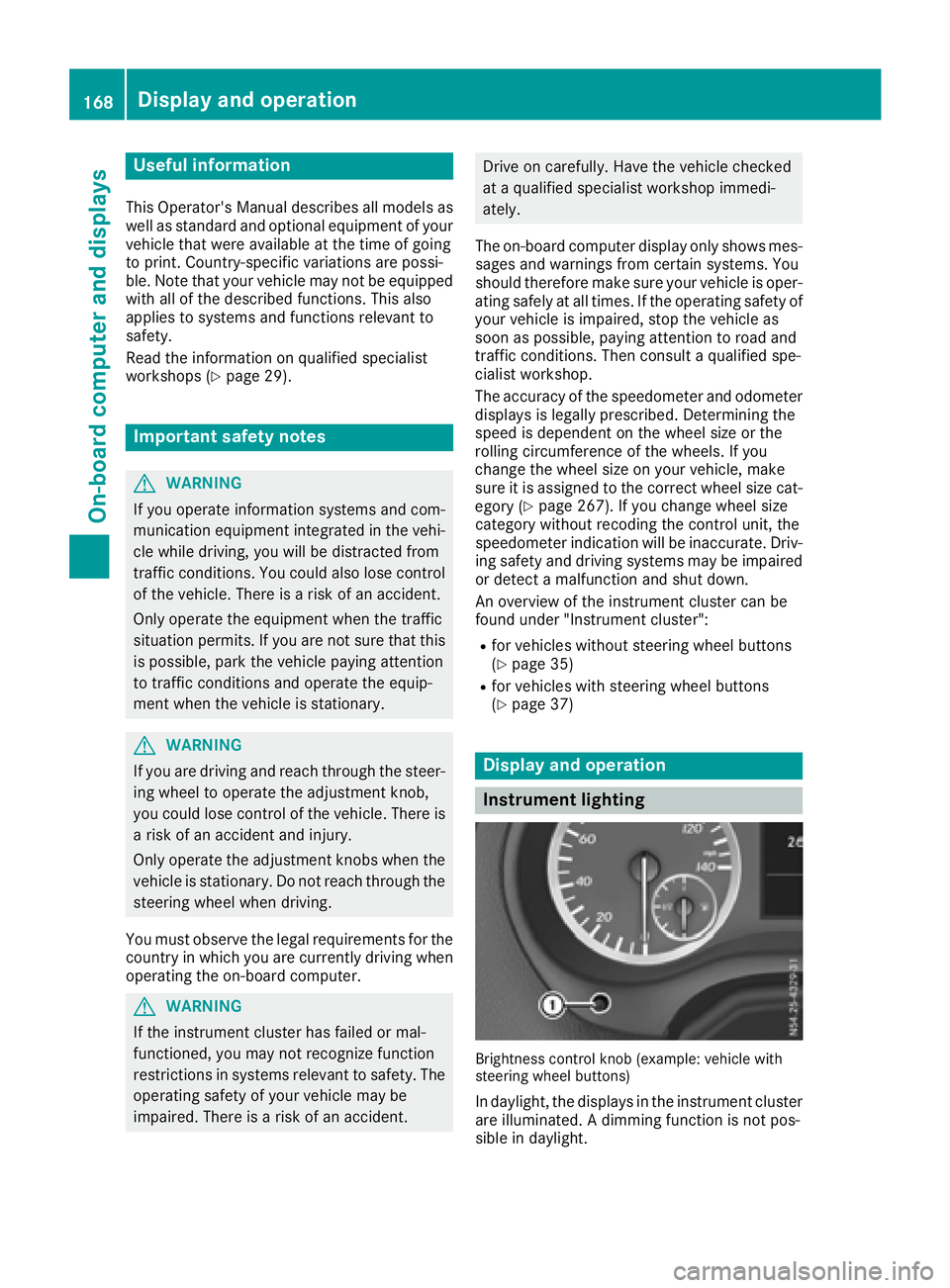
steering wheel buttons)
In daylight, the displays in the instrumentc luster
are illuminated. Adimmingf unction is not pos-
sible in daylight.
168Display and operation
On-boardc omputer and displays