weight MERCEDES-BENZ METRIS 2016 MY16 Operator’s Manual
[x] Cancel search | Manufacturer: MERCEDES-BENZ, Model Year: 2016, Model line: METRIS, Model: MERCEDES-BENZ METRIS 2016Pages: 310, PDF Size: 7.28 MB
Page 285 of 310
Load index
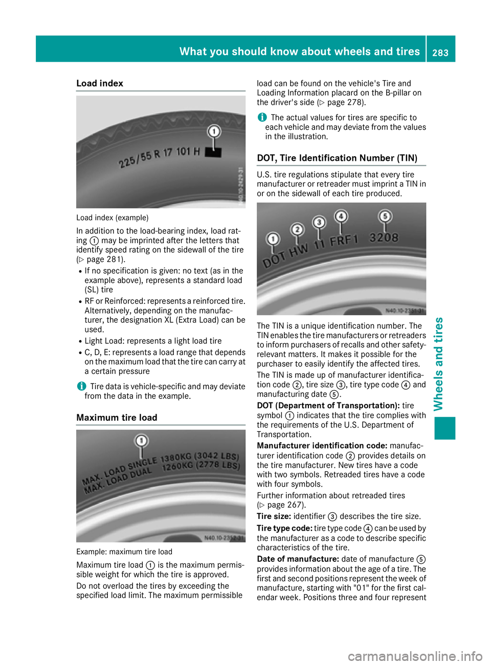
Load index(example)
In addition to th eload-bearin gindex, load rat-
ing :may be imprinted after th eletter sthat
identif yspeed rating on th esidewall of th etire
(
Ypage 281).
RIf no specificatio nisgiven: no tex t(as in the
example above), represents astandar dload
(SL )tire
RRF or Reinforced: represents areinforced tire.
Alternatively, depending on th emanufac-
turer, th edesignation XL (Extr aLoad) can be
used.
RLightL oad: represents alight load tire
RC, D, E: represents aload range that depends
on th emaximum load that th etirec an carry at
ac ertain pressure
iTire data is vehicle-specific and may deviate
fro mt hedata in th eexample.
Maximum tir eload
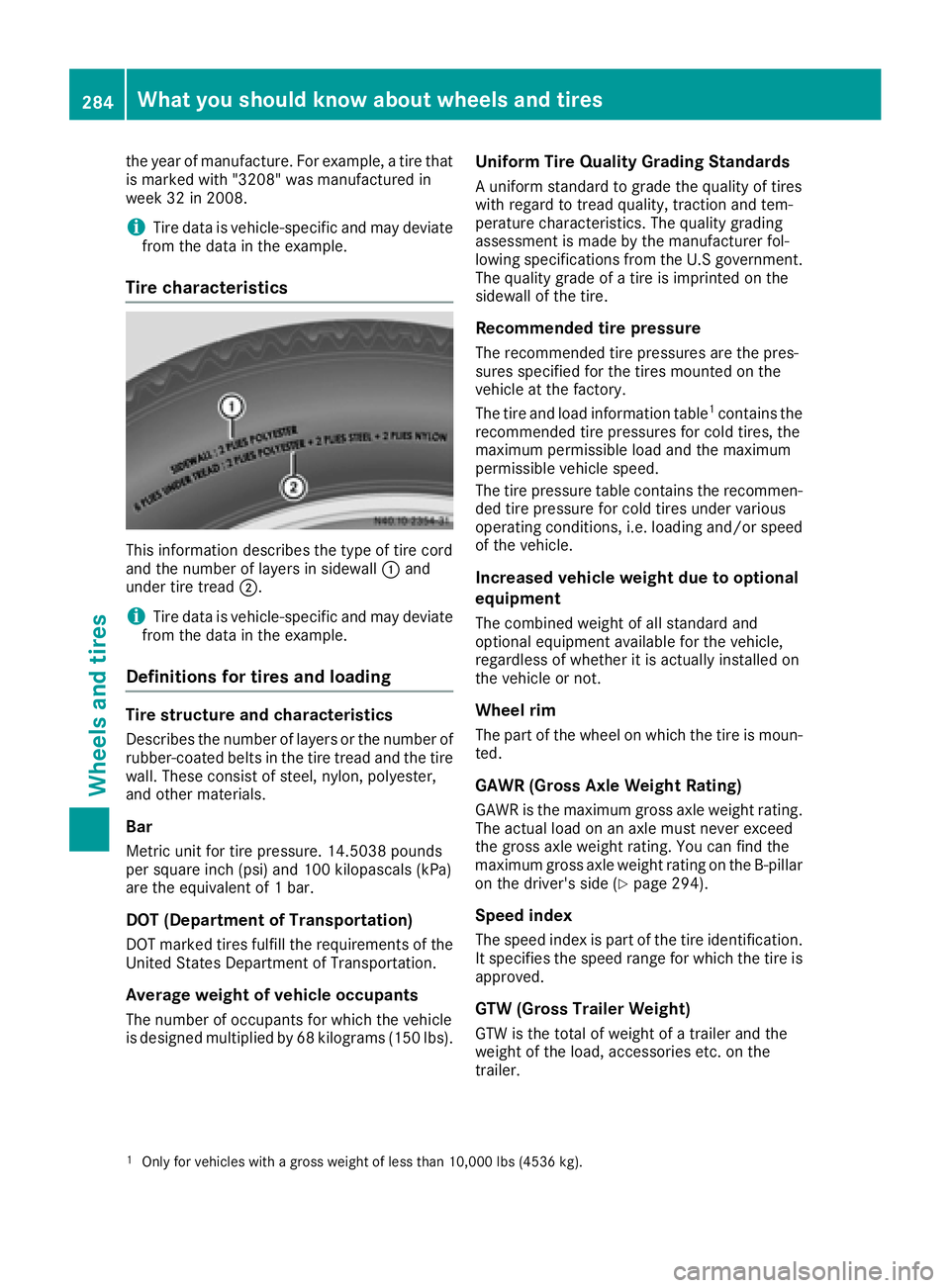
Example: maximum tir eload
Maximum tir eload :is th emaximum permis-
sible weight for whicht hetireisa pproved.
Do not overload th etires by exceedingt he
specified load limit.T he maximum permissible load can be foun
donthevehicle's Tire and
LoadingI nformation placar dontheB-pillar on
th ed river' sside (
Ypage 278).
iThe actual values for tires are specific to
each vehicle and may deviat efromt hevalues
in th eillustration.
DOT, Tir eIdentification Number (TIN)
U.S. tir eregulations stipulatet hate veryt ire
manufacturer or retreaderm ust imprintaTIN in
or on th esidewall of each tir eproduced.
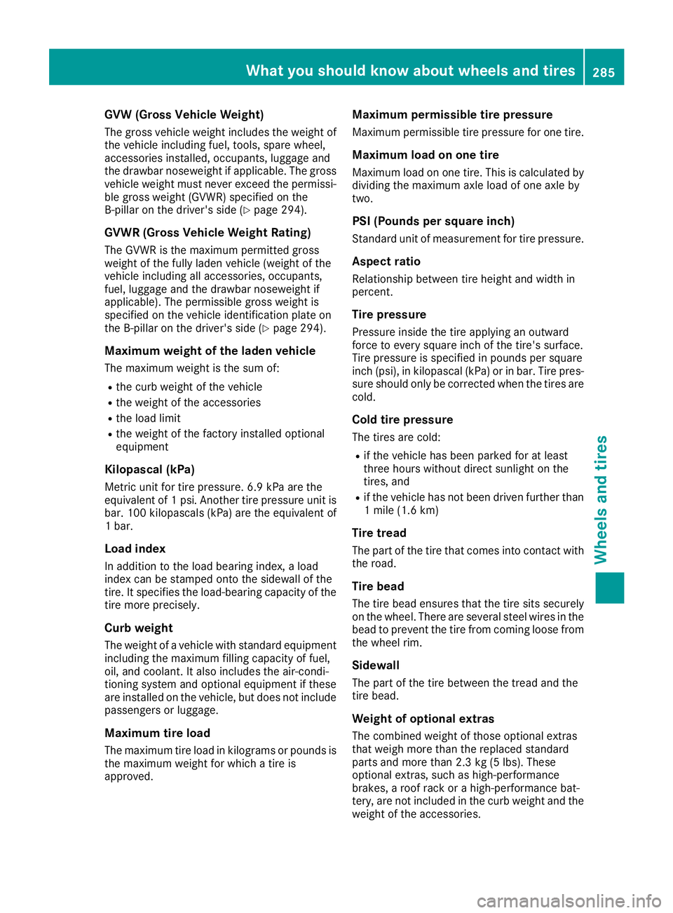
The TIN is aunique identification number. The
TIN enables th etirem anufacturers or retreaders
to inform purchasersofr ecalls and other safety-
relevant matters. It makes it possible for the
purchaser to easily identif ythe affected tires.
The TIN is made up of manufacturer identifica-
tio nc ode ;,t ires ize =,t iret ype code ?and
manufacturing date A.
DOT (Departmen tofTransportation): tire
symbol :indicates that th etirec omplies with
th er equirements of th eU.S.D epartmento f
Transportation.
Manufacturer identification code: manufac-
turer identification code ;provides details on
th et irem anufacturer. New tires have acode
with two symbols. Retreaded tires have acode
with four symbols.
Further informatio nabout retreadedt ires
(
Ypage 267).
Tir es ize: identifier =describes th etires ize.
Tir etyp ec ode: tiret ype code ?can be used by
th em anufacturer as acodetod escribe specific
characteristic softhetire.
Dat eofm anufacture: date of manufacture A
provides informatio nabout th eage of atire. The
first and second positionsr epresenttheweek of
manufacture, starting with "01 "for th efirst cal-
endar week.P ositionsthree and four represent
What you should know aboutw heels and tires283
Wheels and tires
Z
Page 286 of 310
the year of manufacture. For example,atire that
is marked with "3208" wa smanufactured in
week 32 in 2008.
iTire data is vehicle-specific and mayd eviate
fromt he data in the example.
Tire characteristics
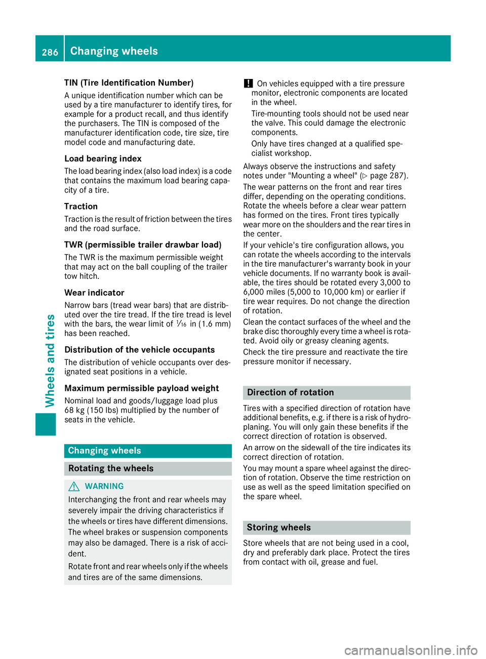
Thisinformation describe sthe typ eoftire cord
and the numbe roflayersins idewall :and
under tire tread ;.
iTire data is vehicle-specific and mayd eviate
fromt he data in the example.
Definition sfor tire sand loading
Tire structure and characteristics
Describe sthe numbe roflayer sort he numbe rof
rubber-coated belts in the tire trea dand the tire
wall .These consis tofsteel,nylon, polyester,
and othe rmaterials.
Bar
Metric uni tfor tire pressure. 14.5038 pounds
pe rs quare inch (psi)a nd 100 kilopascal s(kPa)
ar et he equivalent of 1bar.
DO T(De partmen tofTransportation)
DOT marked tire sfulfill the requirements of the
United State sDepartment of Transportation.
Averag eweigh tofv ehicle occupants
The numbe rofoccupants for which the vehicle
is designe dmultiplie dby68k ilograms (15 0lbs).
Uniform Tire Quality Grading Standards
Au nifor mstandard to grade the quality of tires
with regar dtotreadquali ty,t ractio nand tem-
peratur echaracteristics .The qualit ygrading
assessment is made by the manufacturer fol-
lowing specifications fromt he U.S government.
The quality grade of atire is imprinted on the
sidewall of the tire.
Recommende dtire pressure
The recommended tire pressures ar ethe pres-
sures specifie dfor the tire smounted on the
vehicl eatthe factory.
The tire and load information table
1contains the
recommende dtire pressures for col dtires, the
maximum permissibl eloa da nd the maximum
permis sibleve
hiclespeed.
The tire pressure table contains the recommen-
de dt ire pressure for col dtiresu nder various
operating conditions ,i.e .loadi ng and/or speed
of the vehicle.
Increase dvehicle weight due to optional
equipment
The combine dweigh tofa llstandard and
optional equipment availabl efor the vehicle,
regardles sofwhether it is actually installe don
the vehicl eornot.
Wheel rim
The part of the whee lonwhich the tire is moun-
ted.
GAWR (Gros sAxleW eight Rating)
GAWRisthe maximum gross axl eweigh trating.
The actual load on an axl emustn eve rexceed
the gross axl eweigh trating .You can fin dthe
maximum gross axl eweigh trating on the B-pillar
on the driver's side (
Ypage 294).
Speed index
The spee dindex is part of the tire identification.
It specifie sthe spee drange for which the tire is
approved.
GTW (Gros sTrailer Weight)
GTWist he tota lofweightofat railer and the
weight of the load ,accessorie setc. on the
trailer.
1Onl yfor vehicles with agross weight of less tha n10,000 lb s(4536 kg).
284What yous hould knowabout wheels an dtires
Wheel sand tires
Page 287 of 310
GVW (Gross VehicleWeight)
The gross vehicle weight includes the weight of
the vehicle including fuel ,tools, spare wheel,
accessories installed, occupants, luggage and
the drawbar noseweight if applicable. The gross
vehicle weight must never exceed the permissi-
ble gross weight (GVWR) specified on the
B-pilla ronthe driver's side (
Ypage 294).
GVWR (Gross Vehicl eWeight Rating)
The GVWR is the maximu mpermitted gross
weight of the full yladen vehicle (weight of the
vehicle including all accessories, occupants,
fuel ,luggage and the drawbar noseweight if
applicable).T he permissibleg ross weight is
specified on the vehicle identification plate on
the B-pilla ronthe driver's side (
Ypage 294).
Maximum weight of the laden vehicle
The maximu mweight is the sum of:
Rthe curb weight of the vehicle
Rthe weight of the accessories
Rthe loadl imit
Rthe weight of the factory installed optional
equipment
Kilopascal (kPa)
Metric unit for tire pressure. 6.9 kPa are the
equivalent of 1psi.A nother tire pressure unit is
bar. 100 kilopascals (kPa) are the equivalent of
1b ar.
Load index
In addition to the loadb earing index,aload
index can be stamped onto the sidewal lofthe
tire. It specifies the load-bearing capacity of the
tire more precisely.
Curb weight
The weight of avehicle with standard equipment
including the maximu mfilling capacity of fuel,
oil, and coolant. It also includes the air-condi-
tioning system and optional equipment if these
are installed on the vehicle ,but does not include
passengers or luggage.
Maximum tire load
The maximu mtire loadink ilograms or pounds is
the maximu mweight for which atire is
approved.
Maximum permissiblet ire pressure
Maximumpermissiblet ire pressure for one tire.
Maximum load on one tire
Maximumloadono ne tire. This is calculated by
dividing
the maximu maxle loadofo ne axle by
two.
PSI (Pounds per square inch)
Standard unit of measurement for tire pressure.
Aspec tratio
Relationshi pbetwee ntire heighta nd width in
percent.
Tire pressure
Pressure inside the tire applying an outward
force to every square inch of the tire's surface.
Tire pressure is specified in pounds per square
inch (psi), in kilopascal (kPa) or in bar. Tire pres-
sure shoul donly be corrected when the tires are
cold.
Col dtire pressure
The tires are cold:
Rif the vehicle has been parked for at least
three hours withou tdirect sunlight on the
tires, and
Rif the vehicle has not been driven further than
1m ile (1.6 km)
Tire tread
The part of the tire that comes into contact with
the road.
Tire bead
The tire beade nsures that the tire sits securely
on the wheel. There are severals teel wiresinthe
beadtop revent the tire from coming loose from
the whee lrim.
Sidewall
The part of the tire betwee nthe tread and the
tire bead.
Weight of optional extras
The combined weight of those optional extras
that weigh more than the replaced standard
parts and more than 2.3 kg (5 lbs). These
optional extras, such as high-performance
brakes, aroof rack or ahigh-performance bat-
tery, are not included in the curb weight and the weight of the accessories.
What you shouldk now about wheels and tires285
Wheelsand tires
Z
Page 288 of 310
TIN (Tire IdentificationNumber)
Auniqu eide ntificatio nnumbe rwhich can be
used by atire manufacturer to identify tires, for
exampl efor ap roduct recall ,and thusi dentify
the purchasers. The TIN is compose dofthe
manufacturer identificatio ncode, tire size, tire
model cod eand manufacturing date.
Load bearin gind ex
The load bearing index (als oloa dindex) is acode
thatc ontains the maximu mloadb eari ng capa-
city of atire.
Traction
Tractio nist he resul toffrictio nbetween the tires
and the roa dsurface.
TWR (permissibl etrailer drawbar load)
The TWRist he maximumpermissibl eweigh t
thatm ayact on the ball coupling of the trailer
tow hitch.
Wea rind icator
Narrowb ars( tread wear bars) thata redistrib-
ute doverthe tire tread. If the tire trea dislevel
with the bars, the wear limit of áin (1.6 mm)
hasb eenr eached.
Distribution of the vehicle occupants
The distributio nofvehicleoccupants ove rdes-
ignate dseatp osit ions in avehicle.
Maximum permissible payload weight
Nomina lloa da nd goods/luggage load plus
68 kg (150 lb s)multiplie dbythe number of
seats in the vehicle.
Changing wheels
Rotating the wheels
GWARNING
Interchanging the front and rear wheels may
severelyi mpair the driving characteristics if
the wheels or tires have different dimensions. The whee lbrakes or suspension components
may als obedamaged. There is arisk of acci-
dent.
Rotate front and rear wheels only if the wheels and tires are of the same dimensions.
!On vehicles equippedw ithatire pressure
monitor, electronic components are located
in the wheel.
Tire-mounting tools should not be used near
the valve .This could damage the electronic
components.
Only have tires changed at aqualified spe-
cialist workshop.
Always observe the instructions and safety
notes under "Mounting awheel" (
Ypage 287).
The wea rpatterns on the front and rear tires
differ, depending on the operating conditions.
Rotate the wheels before aclear wea rpattern
has formed on the tires. Front tires typically
wea rmore on the shoulders and the rear tires in
the center.
If you rvehicle's tire configuration allows, you
can rotate the wheels according to the intervals
in the tire manufacturer's warranty book in your
vehicled ocuments. If no warranty book is avail-
able, the tires should be rotated every 3,000 to
6,000 mile s(5,000 to 10,000 km) or earlier if
tire wea rrequires. Do not change the direction
of rotation.
Clean the contact surfaces of the whee land the
brake disc thoroughly every time awheelisr ota-
ted. Avoid oily or greas ycleaning agents.
Check the tire pressure and reactivate the tire
pressure monitor if necessary.
Directio nofrotation
Tires with aspecified directio nofrotation have
additional benefits, e.g. if there is arisk of hydro-
planing. You wil lonly gai nthese benefits if the
correct directio nofrotation is observed.
An arrow on the sidewal lofthe tire indicates its
correct directio nofrotation.
You may mount aspare whee lagainst the direc-
tion of rotation. Observe the time restriction on
use as wel lasthe speed limitation specified on
the spare wheel.
Storing wheels
Store wheels that are not being used in acool,
dry and preferably dark place. Protect the tires
from contact with oil, greas eand fuel.
286Changing wheels
Wheel sand tires
Page 296 of 310

Useful information
This Operator's Manual describes all models as
well as standard and optional equipment of your
vehicle that were available at the time of going
to print.Country-specific variation sare possi-
ble. Note that your vehicle may not be equipped
with all of the described functions. This also
applies to system sand function srelevantt o
safety.
Read the information on qualified specialist
workshops (
Ypage 29).
Vehicle electronics
Tampering with the engine electron-
ics
!
Only have engin eelectronics and the corre-
spondin gparts, such as contro lunits ,actua-
tors, sensors or connector leads, serviced at a
qualified specialist workshop. Otherwise, the
vehicle parts may wear more quickly. This can
lead to loss of the New Vehicle Limited War-
ranty.
Installing electrical or electronic
equipment
You and other scan suffer health-related dam-
age through electromagnetic radiation .Byusing
an exterior antenna, apossible health risk
caused by electromagnetic fields, as discussed
in scientific circles, is taken int oaccount. Only
have the exterior antenn ainstalled by aqualified
specialist workshop.
Electrical and electronic devices may have a
detrimental effectonb oth the comfort and the
operatin gsafetyoft he vehicle. If equipment of
this kin disinstalled, its electromagnetic com-
patibility must be checked and verified.
If thes edevices are linked to function sassoci-
ated with resistance to interference, they must
have type approval. This applies to the device or
its interfaces to the vehicle electronics, e.g.
chargingb rackets.
At elephon eortwo-way radio to be installed in
the vehicle must be approved. Further informa-
tion can be found in any Mercedes-Benz Com-
mercial Van Center. For operatio
nofmobile phones and two-way
radios, Mercedes-Benz recommends connec-
tion to an approved exterior antenna. This is the
only way to ensure optimum reception quality
inside the vehicle and to minimize mutual inter-
ference between the vehicle electronics, mobile
phones and two-way radios.
The transmission output of the mobile phone or
two-way radio may not exceed the following
maximum transmission output (PEAK):
Frequency rangeMaximum trans-
mission output
(PEAK)
Shortwave
(f <50M Hz)100 W
4mwaveband30 W
2mwaveband50 W
Trunked radio/Tetra35 W
70 cm waveband35 W
GSM/UMTS/LTE10 W
Identification plates
Vehicle identification platew ith vehi-
cle identification number (VIN)
Vehicle identification plate on the driver's side B-
pillar
XOpen the driver’s door.
You will see vehicle identification plate :
with the vehicle identification number (VIN),
the paint code and the permissible weight
data.
294Identification plates
Technical data
Page 306 of 310
Cargo tie-down points and carriersys-
tems
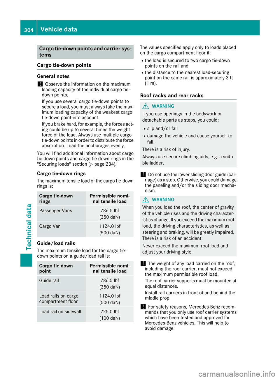
Cargo tie-down points
General notes
!Observ ethe informatio nonthemaximum
loadingc apacity of th eindividua lcargo tie-
down points.
If you use several cargo tie-down points to
secure aload, you must always tak ethe max-
imum loadingc apacity of theweakest cargo
tie-down pointi ntoa ccount.
If you brak ehard ,for example ,the forces act-
ing coul dbeuptos everal times th eweight
force of th eload. Always use multiple cargo
tie-down points in order to distribut ethe force
absorption.L oad theanchorages evenly.
You will fin dadditional informatio nabout cargo
tie-down points and cargo tie-down rings in the
"Securin gloads"s ection(
Ypage 234).
Cargo tie-down rings
The maximum tensile load of th ecargo tie-down
rings is:
Cargo tie-down
ringsPermissible nomi- nal tensile load
Passenger Vans786. 5lbf
(35 0daN)
Cargo Van1124.0 lbf
(50 0daN)
Guide/load rails
The maximum tensile load for th ecargo tie-
down points on aguide/load rail is:
Cargo tie-down
pointPermissible nomi-
nal tensile load
Guide rail786. 5lbf
(35 0daN)
Load rails on cargo
compartmen tfloor1124.0 lbf
(50 0daN)
Load rail on sidewall225. 0lbf
(10 0daN)
The values specifie dapply only to loads placed
on th ecargo compartmen tfloo rif:
Rth el oad is secured to two cargo tie-down
points on th erail and
Rthed istanc etotheneares tload-securing
pointont hesame rail is approximately 3ft
(1 m).
Roo fracks and rear racks
GWARNING
If yo uuseopenings in the bodywork or
detachabl eparts as steps, yo ucould:
Rslipa nd/or fall
Rdamag ethe vehicl eand cause yourselft o
fall.
There is ariskofi njury.
Alway susesecure climbing aids, e.g. asuita-
bl el adde r.
!Do not us ethe lowe rsliding doo rguide (car-
riage) as astep .Otherwise, yo ucould damage
the paneling and/or the sliding doo rmecha-
nism.
GWARNING
Whe nyou load the roof, the center of gravity
of the vehicl erises and the driving character-
istics change. If yo uexcee dthe maximum roof
load ,the driving characteristics, as well as
steering and braking, will be greatl yimpaired.
There is ariskofana ccident.
Neve rexcee dthe maximum roo floa da nd
adjust your driving style.
!The weight of any load carrie donthe roof,
including the roo fcarrier, mus tnot exceed
the maximum permissible roo fload.
The roo fcarrie rsuppo rts mus tbem ounted at
equal distances.
Install rai lcarriers in front of and behind the
middl eprop.
!For safety reasons,M ercedes-Benz recom-
mend sthat yo uonly us eroofcarrie rsystems
which have bee nteste dand approved for
Mercedes-Benz vehicles. Thi swillh elpt o
avoid damage.
304Vehicl edata
Technical data
Page 307 of 310
Maximum roof load330 lbs (150 kg)
with at least three
pairs of support
points
Maximum load for a
rear-mounted cycle
rack154 lbs (70 kg)
for up to four bicycles
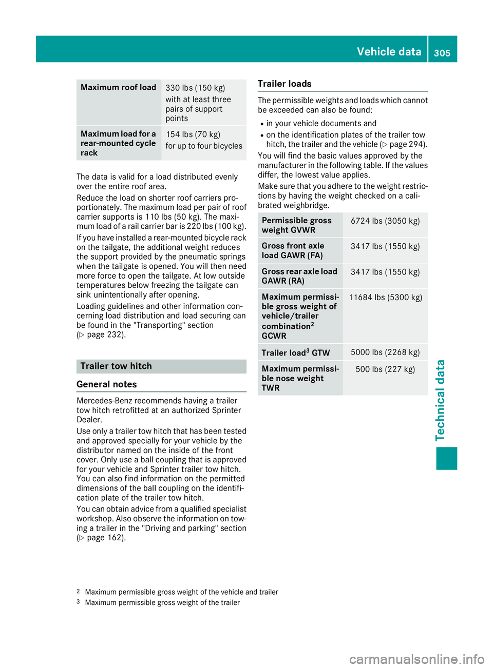
The data is validfor aloadd istributed evenly
over the entire roof area.
Reduce the loa donshorter roof carriers pro-
portionately. The maximu mloadp er pai rofroof
carrie rsupports is 110 lbs (50 kg) .The maxi-
mum loa dofarail carrie rbar is 220 lbs (100 kg).
If you have installed arear-mounted bicycle rack
on the tailgate, the additiona lweight reduces
the support provided by the pneumatic springs
when the tailgate is opened.Y ou willthen need
more force to open the tailgate. At low outside
temperatures belowf reezing the tailgate can
sink unintentionally after opening.
Loading guidelines and other information con-
cerning loa ddistribution and loads ecuring can
be found in the "Transporting" section
(
Ypag e232).
Trailer tow hitch
General notes
Mercedes-Benz recommends having atrailer
tow hitch retrofitted at an authorized Sprinter
Dealer.
Use only atrailer tow hitch that has been tested
and approved specially for you rvehicl ebyt he
distributor named on the insid eofthe front
cover. Only use aballc oupling that is approved
for you rvehicl eand Sprinter trailer tow hitch.
You can als ofind information on the permitted
dimensions of the bal lcoupling on the identifi-
cation plate of the trailer tow hitch.
You can obtai nadvice from aqualified specialist
workshop .Also observe the information on tow-
ing atrailer in the "Driving and parking" section
(
Ypag e162).
Trailer loads
The permissible weights and loads which cannot
be exceededc an alsobefound:
Rin you rvehicl edocuments and
Ron the identification plates of the trailer tow
hitch, the trailer and the vehicl e(Ypage294).
You wil lfind the basi cvalues approved by the
manufacturer in the following table .Ifthe values
differ, the lowest valu eapplies.
Make sure that you adhere to the weight restric-
tions by having the weight checked on acali-
brated weighbridge.
Permissible gross
weight GVWR6724 lbs (3050 kg)
Gross front axle
load GAWR (FA)3417 lbs (1550 kg)
Gross rear axle load
GAWR (RA)3417 lbs (1550 kg)
Maximum permissi-
ble gross weight of
vehicle/trailer
combination
2
GCWR
11684 lbs (5300 kg)
Trailer load3GTW5000 lbs (2268 kg)
Maximum permissi-
ble nose weight
TWR500 lbs (227 kg)
2Maximu mpermissibleg ross weight of the vehiclea nd trailer3Maximumpermissibl egross weight of the trailer
Vehicle data305
Technical data
Z