wheel MERCEDES-BENZ METRIS 2019 MY19 Operator’s Manual
[x] Cancel search | Manufacturer: MERCEDES-BENZ, Model Year: 2019, Model line: METRIS, Model: MERCEDES-BENZ METRIS 2019Pages: 318, PDF Size: 5.07 MB
Page 301 of 318
Mounting a wheel
Vehicle preparation
XStop the vehicle as far away as possible from
traffic and on a level, firm and non-slip sur-
face.
XIf your vehicle poses a risk to approaching
traffic, switch on the hazard warning lamps.
XApply the parking brake.
XTurn the front wheels to the straight-ahead
position.
XShift the transmission to position P.
XSwitch off the engine.
XPassengers should leave the vehicle. Make
sure that the passengers are not endangered
as they do so.
XMake sure that no one is near the danger area
while the wheel is being changed. Anyone
who is not directly assisting in the wheel
change should, for example, stand behind the
barrier.
XPlace the warning triangle or warning lamp at
a suitable distance.
Observe the legal requirements on the cor-
rect use of the warning triangle or warning
lamp for the country in which you are cur-
rently driving
XSecure the vehicle to prevent it from rolling
away.
Observe the safety notes on parking under
"Driving and parking" (
Ypage 135)
XOn level terrain: place chocks or other suit-
able objects under the front and rear of the
wheel that is diagonally opposite the wheel to
be changed.
XOn slight inclines: place chocks or other
suitable objects under the wheels on the front and rear axles opposite the wheel to be
changed.
XIf included in the vehicle equipment, take the
tire-changing tool kit out of the vehicle tool kit
(
Ypage 272).
Apart from some country-specific variants,
vehicles are not equipped with tire-changing
tools. Some tools for changing a wheel are
specific to the vehicle. Consult a qualified
specialist workshop for more information on
which tools are required to perform a wheel
change on your vehicle.
XIf included in the vehicle equipment, remove
the spare wheel from the spare wheel bracket (
Ypage 303). Observe the safety notes listed
under "Spare wheel" (Ypage 303).
XCarefully remove the hub caps.
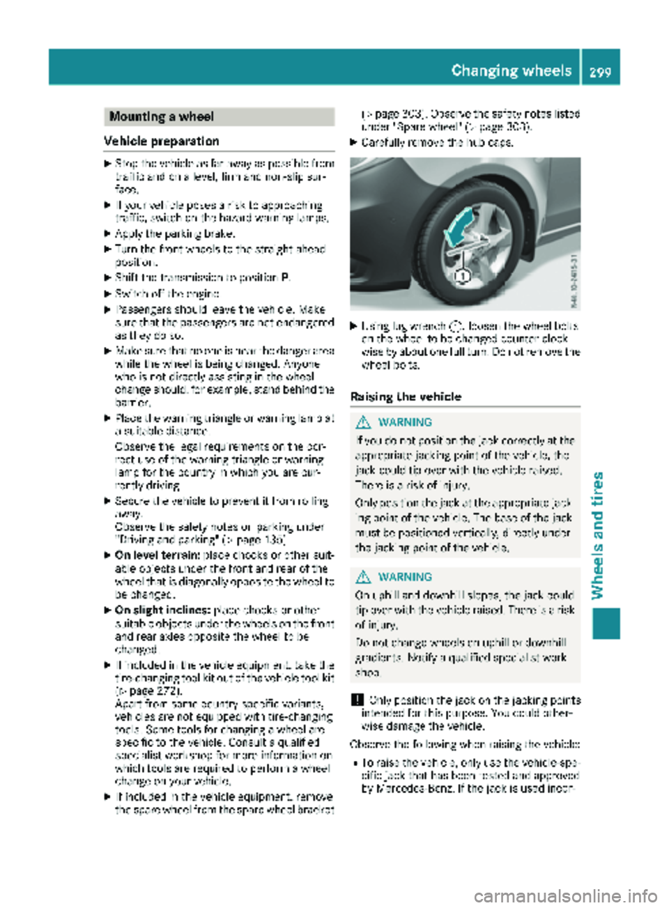
XUsing lug wrench :, loosen the wheel bolts
on the wheel to be changed counter-clock-
wise by about one full turn. Do not remove the
wheel bolts.
Raising the vehicle
GWARNING
If you do not position the jack correctly at the
appropriate jacking point of the vehicle, the
jack could tip over with the vehicle raised.
There is a risk of injury.
Only position the jack at the appropriate jack-
ing point of the vehicle. The base of the jack
must be positioned vertically, directly under
the jacking point of the vehicle.
GWARNING
On uphill and downhill slopes, the jack could
tip over with the vehicle raised. There is a risk
of injury.
Do not change wheels on uphill or downhill
gradients. Notify a qualified specialist work-
shop.
!Only position the jack on the jacking points
intended for this purpose. You could other-
wise damage the vehicle.
Observe the following when raising the vehicle:
RTo raise the vehicle, only use the vehicle-spe-
cific jack that has been tested and approved
by Mercedes-Benz. If the jack is used incor-
Changing wheels299
Wheels and tires
Z
Page 302 of 318
rectly, it could tip over while the vehicle is
raised.
RThe vehicle's jack is intended only to raise the
vehicle for a short time when changing a
wheel. It is not suited for performing mainte-
nance work under the vehicle.
RAvoid changing the wheel on uphill and down-
hill slopes.
RBefore raising the vehicle, secure it from roll-
ing away by applying the parking brake and
inserting wheel chocks. Never disengage the
parking brake while the vehicle is raised.
RThe jack must be placed on a firm, flat and
non-slip surface. On a loose surface, a large,
load-bearing underlay must be used. On a
slippery surface, a non-slip underlay must be
used, e.g. rubber mats.
RMake sure that the distance between the
underside of the tires and the ground does not
exceed 1.2 in(3 cm).
RNever place your hands or feet under the
raised vehicle.
RNever lie under the raised vehicle.
RNever start the engine when the vehicle is
raised.
RNever open or close a door or the tailgate/
door when the vehicle is raised.
RMake sure that no persons are present in the
vehicle when the vehicle is raised.
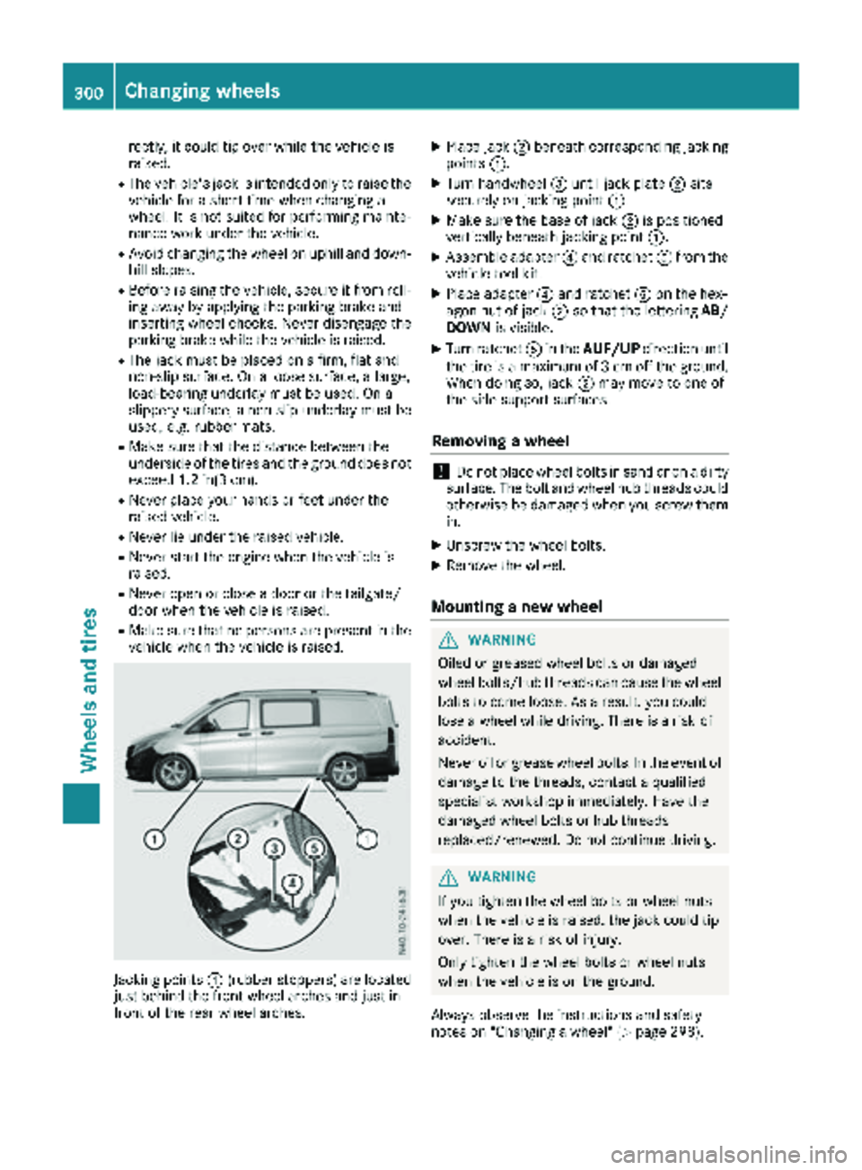
Jacking points :(rubber stoppers) are located
just behind the front wheel arches and just in
front of the rear wheel arches.
XPlace jack ;beneath corresponding jacking
points :.
XTurn handwheel =until jack plate ;sits
securely on jacking point :.
XMake sure the base of jack ;is positioned
vertically beneath jacking point :.
XAssemble adapter?and ratchet Afrom the
vehicle tool kit.
XPlace adapter ?and ratchet Aon the hex-
agon nut of jack ;so that the lettering AB/
DOWN is visible.
XTurn ratchet Ain the AUF/UP direction until
the tire is a maximum of 3 cm off the ground.
When doing so, jack ;may move to one of
the side support surfaces.
Removing a wheel
!Do not place wheel bolts in sand or on a dirty
surface. The bolt and wheel hub threads could
otherwise be damaged when you screw them
in.
XUnscrew the wheel bolts.
XRemove the wheel.
Mounting a new wheel
GWARNING
Oiled or greased wheel bolts or damaged
wheel bolts/hub threads can cause the wheel bolts to come loose. As a result, you could
lose a wheel while driving. There is a risk of
accident.
Never oil or grease wheel bolts. In the event of
damage to the threads, contact a qualified
specialist workshop immediately. Have the
damaged wheel bolts or hub threads
replaced/renewed. Do not continue driving.
GWARNING
If you tighten the wheel bolts or wheel nuts
when the vehicle is raised, the jack could tip
over. There is a risk of injury.
Only tighten the wheel bolts or wheel nuts
when the vehicle is on the ground.
Always observe the instructions and safety
notes on "Changing a wheel" (
Ypage 298).
300Changing wheels
Wheels and tires
Page 303 of 318
Only use wheel bolts that have been designed
for the wheel and the vehicle. For safety rea-
sons, Mercedes-Benz recommends that you
only use wheel bolts which have been approved
for Mercedes-Benz vehicles and the respective
wheel.
!On vehicles equipped with a tire pressure
monitor, electronic components are located
in the wheel.
Tire-mounting tools should not be used near
the valve. This could damage the electronic
components.
Only have tires changed at a qualified spe-
cialist workshop.
XClean the wheel and wheel hub contact sur-
faces.
XSlide the new wheel onto the wheel hub and
push it on.
XScrew in the wheel bolts and tighten them
lightly.
Lowering the vehicle
GWARNING
The wheels could work loose if the wheel nuts and bolts are not tightened to the specified
tightening torque. There is a risk of accident.
Have the tightening torque immediately
checked at a qualified specialist workshop
after a wheel is changed.
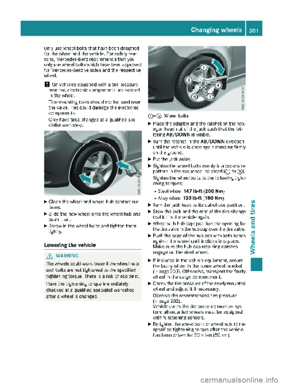
:—AWheel bolts
XPlace the adapter and the ratchet on the hex-
agon head nut of the jack such that the let-
tering AB/DOWN is visible.
XTurn the ratchet in the AB/DOWNdirection
until the vehicle is once again standing firmly
on the ground.
XPut the jack aside.
XTighten the wheel bolts evenly in a crosswise
pattern in the sequence indicated (: toA).
Tighten the wheel bolts to the following tight-
ening torques:
RSteel wheel 147 lb-ft(200 Nm)
RAlloy wheel 133 lb-ft(180 Nm)
XTurn the jack back to its out-of-use position.
XStow the jack and the rest of the tire-change
tool kit in the vehicle again.
XWheel with hub cap: position the opening for
the tire valve in the hub cap over the tire valve.
XPush the edge of the hub cap with both hands
against the wheel until it clicks into place.
Make sure the hub cap retaining catches
engage on the steel wheel.
XIf included in the vehicle equipment, secure
the faulty wheel in the spare wheel bracket
(
Ypage 303). Otherwise, transport the faulty
wheel in the cargo compartment.
XCheck the tire pressure of the newly mounted
wheel and adjust it if necessary.
Observe the recommended tire pressure
(
Ypage 282).
Vehicles with the tire pressure monitor sys-
tem: all mounted wheels must be equipped
with functioning sensors.
XRetighten the wheel bolts or wheel nuts to the
specified tightening torque after the vehicle
has been driven for 30 miles (50 km).
Changing wheels301
Wheels and tires
Z
Page 304 of 318
When using a wheel/spare wheel with a new or
newly painted wheel rim, have the wheel bolts/
nuts retightened again after approximately 600
to 3,000 miles (1,000 to 5,000 km). Observe the
specified tightening torque.
Wheel and tire combination
General notes
!
Retreaded tires are neither tested nor rec-
ommended by Mercedes-Benz, since previ-
ous damage cannot always be detected on
retreaded tires. As a result, Mercedes-Benz
cannot guarantee vehicle safety if retreaded
tires are mounted. Do not mount used tires if you have no information about their previous
usage.
!For safety reasons, Mercedes-Benz recom-
mends that you only use tires, wheels and
accessories which have been specially
approved by Mercedes-Benz for your vehicle.
These tires have been specially adapted for
use with the driving safety systems, such as
ABS or ESP
®.
Only use tires, wheels or accessories tested
and approved by Mercedes-Benz. Certain
characteristics, e.g. handling, vehicle noise
emissions or fuel consumption, may other-
wise be adversely affected. In addition, when
driving with a load, tire dimension variations
could cause the tires to come into contact
with the bodywork and axle components. This could result in damage to the tires or the vehi-
cle.
Mercedes-Benz accepts no liability for dam-
age resulting from the use of tires, wheels or
accessories other than those tested and
approved.
Further information on wheels, tires and
approved combinations can be obtained from
any qualified specialist workshop.
!Large wheels: the lower the section width
for a certain wheel size, the lower the ride
comfort is on poor road surfaces. Roll comfort and suspension comfort are reduced and the
risk of damage to the wheels and tires as a
result of driving over obstacles increases.
You will find a table with the recommended tire
pressures for various vehicle loads on the inside
of your vehicle's fuel filler flap or under "Tire
pressure tables" (
Ypage 290). You can find fur-
ther information under "Tire pressure"
(
Ypage 282).
Check tire pressures regularly and only when
the tires are cold.
Notes on the vehicle equipment – always equip
the vehicle:
Rwith tires of the same size across an axle
(left/right)
Rwith the same type of tires on all wheels at a
given time (summer tires, winter tires)
iNot all wheel/tire combinations can be
installed at the factory in all countries.
Tires
R 17
TiresSteel wheels
225/55 R17 RF (XL) 101V6.5 J x 17 H2 ET 50
225/55 R17 RF (XL) 101H6.5 J x 17 H2 ET 50
R 17
TiresAlloy wheels
225/55 R17 RF (XL) 101V7 J x 17 H2 ET 51
225/55 R17 RF (XL) 101H7 J x 17 H2 ET 51
302Wheel and tire combination
Wheels and tires
Page 305 of 318
Spare wheel
Important safety notes
GWARNING
Wheel and tire dimensions as well as the type of tire can vary between the spare wheel and
the wheel to be replaced. When the spare
wheel is mounted, driving characteristics may be severely affected. There is a risk of an acci-
dent.
In order to reduce risks:
Ryou should therefore adapt your driving
style and drive carefully.
Rnever mount more than one spare wheel
that differs from the wheel to be replaced.
Ronly use a spare wheel that differs from the
wheel to be replaced for a short time.
Rdo not deactivate ESP®.
Rhave a spare wheel that differs from the
wheel that has been changed replaced at
the nearest qualified specialist workshop.
You must observe the correct wheel and
tire dimensions as well as the wheel type.
When using a spare wheel of a different size, do
not exceed the maximum permissible speed of
50 mph (80 km/h).
General notes
The procedure for mounting the spare wheel is
described in "Mounting a wheel" (Ypage 299).
The following should be checked regularly, par-
ticularly prior to long journeys:
Rthe tire pressure of the spare wheel, which
should then be corrected if necessary
(
Ypage 282)
Rthe fastenings of the spare wheel bracket
The spare wheel is located either in the left rear
compartment or in a spare wheel bracket under
the vehicle.
Replace the tires after six years at the latest,
regardless of wear. This also applies to the spare
wheel.
Vehicles with tire pressure monitor: the
spare wheel is not equipped with a sensor for
monitoring tire pressure. If you have installed a spare wheel, the tire pressure monitor will not
function for this wheel. The system may con-
tinue to show the tire pressure of the wheel that
has been removed for a few minutes. The value
displayed for the position where the spare wheel
is installed is not the same as the current tire
pressure of the spare wheel.
When you are driving with the spare wheel
mounted, the tire pressure monitor cannot func-
tion reliably. Only restart the tire pressure mon- itor when the defective wheel has been replaced
with a new wheel and sensor.
More Information can be found under "Tire pres-
sure monitor" (
Ypage 286).
Removing and installing the spare
wheel
Spare wheel under the rear of the vehi-
cle
Removing
XTake the lug wrench and auxiliary tool for the
spare wheel lifter out of the vehicle tool kit
(
Ypage 272).
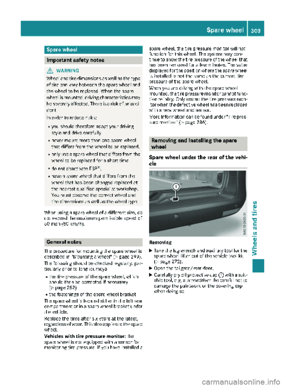
XOpen the tailgate/rear door.
XCarefully pry off protective cap :with a suit-
able tool, e.g. a screwdriver. Be careful not to
damage the paintwork or the covering cap
when doing so.
Spare wheel303
Wheels and tires
Z
Page 306 of 318
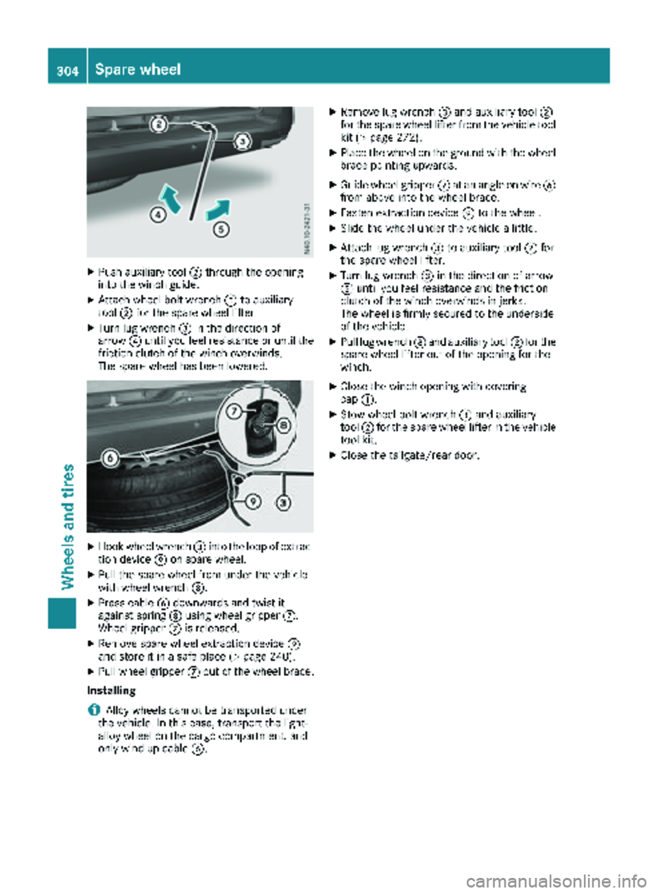
XPush auxiliary tool;through the opening
into the winch guide.
XAttach wheel bolt wrench =to auxiliary
tool ;for the spare wheel lifter.
XTurn lug wrench =in the direction of
arrow ?until you feel resistance or until the
friction clutch of the winch overwinds.
The spare wheel has been lowered.
XHook wheel wrench =into the loop of extrac-
tion device Eon spare wheel.
XPull the spare wheel from under the vehicle
with wheel wrench =.
XPress cableBdownwards and twist it
against spring Dusing wheel gripper C.
Wheel gripper Cis released.
XRemove spare wheel extraction device E
and store it in a safe place (Ypage 240).
XPull wheel gripper Cout of the wheel brace.
Installing
iAlloy wheels cannot be transported under
the vehicle. In this case, transport the light-
alloy wheel on the cargo compartment, and
only wind up cable B.
XRemove lug wrench =and auxiliary tool ;
for the spare wheel lifter from the vehicle tool
kit (
Ypage 272).
XPlace the wheel on the ground with the wheel brace pointing upwards.
XGuide wheel gripper Cat an angle on wire B
from above into the wheel brace.
XFasten extraction device Eto the wheel.
XSlide the wheel under the vehicle a little.
XAttach lug wrench =to auxiliary tool ;for
the spare wheel lifter.
XTurn lug wrench =in the direction of arrow
A until you feel resistance and the friction
clutch of the winch overwinds in jerks.
The wheel is firmly secured to the underside
of the vehicle.
XPull lug wrench =and auxiliary tool ;for the
spare wheel lifter out of the opening for the
winch.
XClose the winch opening with covering
cap :.
XStow wheel bolt wrench =and auxiliary
tool ;for the spare wheel lifter in the vehicle
tool kit.
XClose the tailgate/rear door.
304Spare wheel
Wheels and tires
Page 311 of 318
The following components of the different vehi-
cle versions influence fuel consumption:
Rtire sizes, tire tread, tire pressure, tire condi-
tion
Rtransmission ratios for the drive assemblies
Radditional equipment (e.g. air-conditioning
system, auxiliary heating system)
For these reasons, the actual consumption fig-
ures for your vehicle may deviate from the con-
sumption figures determined according to EU
Directive 80/1268/EE C.
Details on fuel consumption can be called up in
the on-board computer:
Ron vehicles without steering wheel buttons
(Ypage 174)
Ron vehicles with steering wheel buttons
(Ypage 181)
Engine oil
General notes
When handling engine oil, observe the important
safety notes on operating fluids (Ypage 306).
The quality of the engine oil used is of decisive
importance for the engine's functionality and
operating life. Mercedes-Benz continually
approves engine oils based on complex experi-
ments according to the current state of the art. Therefore, only Mercedes-Benz approved
engine oils may be used in Mercedes-Benz
engines. Mercedes-Benz recommends having
the oil changed at a qualified specialist work-
shop. Information about engine oils approved by
Mercedes-Benz can be obtained:
Rfrom any Mercedes-Benz Commercial Van
Center
Ron the Internet at
http://bevo.mercedes-benz.co
mbyenterin g
th edesignation ,e.g. 229.5.
Mercedes-Ben zapprova lis indicate don th eoil
container by th einscription „MB-Freigabe “or
„MB Approval“ and th ecorrespondin gdesigna-
tion ,e.g. MB-Freigabe or MB Approval 229.5.
Designation sof th eapprove dengin eoils for
your vehicl e
MB-Freigabe or MB
Approval229.5
Mercedes-Ben zrecommends that you only use
approve dmultigrade engin eoils of th eSA E
classe sSA E0W-30 and SA E0W-40 or
SA E5W-30 and SA E5W-40. These engin eoils
ensur eoptimum lubrication eve nat ver ylow
outside temperatures (
Ypage 310).
Whe ntoppin gup, we recommen dthat you only
use engin eoil of th esam egrade (MB-Freigabe
or MB Approval designation )and SA Eclass as
th eoil filled at th elast oil change.
iIf th eengin eoils listed in th etable are no t
available, you may add th efollowin gengin e
oils until th enext oil change:
RMB-Freigabe or MB Approval 229.1, or
ACE AA3
This mus tonly be added once and th eamount
mus tno tbe greate rthan 1qt (1. 0l).
Subsequentl yhav eth eengin eoil changed at
th eearliest possibl eopportunity.
!Using engin eoils of another grade qualit yis
no tpermitted.
Capacities
!Do no tadd to omuc hoil. addin gto omuc h
engin eoil can result in damage to th eengin e
or to th ecatalytic converter. Hav eexcess
engin eoil siphoned off .
Oil change includin goil filter
Engin eoilApprox. 2US gal
(7.75 l)
Service products and capacities309
Technical data
Z
Page 316 of 318
The dimensions specified vary according to:
RTires
RLoad
RCondition of the suspension
ROptional equipment
ModelCargo Van
Opening height of the
tailgate:86.0 in (2185 mm)
Opening range of the
tailgate;41.2 in (1047 mm)
Opening range of the
rear doors =33.4 in (849 mm)
Load width50.0 in (1270 mm)
Max. load width66.3 in (1685 mm)
Load height53.8 in (1367 mm)
Vehicle length202.4 in
(5140 mm)
Vehicle width
Including exterior mir-
rors
Excluding exterior mir-
rors
88.3 in (2244 mm)
75.9 in (1928 mm)
Wheelbase126.0 in
(3200 mm)
ModelPassenger Vans
Opening height of the
tailgate :84.6 in (2150 mm)
Opening range of the
tailgate;41.2 in (1047 mm)
Opening range of the
rear doors =33.4 in (849 mm)
Load width47.4 in (1205 mm)
Max. load width61.1 in (1552 mm)
Load height52.2 in (1326 mm)
Vehicle length202.4 in
(5140 mm)
ModelPassenger Vans
Vehicle width
Including exterior mir-
rors
Excluding exterior mir-
rors
88.3 in (2244 mm)
75.9 in (1928 mm)
Wheelbase126.0 in
(3200 mm)
Cargo tie-down points and carrier sys-
tems
Cargo tie-down points
General notes
!Observe the information on the maximum
loading capacity of the individual cargo tie-
down points.
If you use several cargo tie-down points to
secure a load, you must always take the max-
imum loading capacity of the weakest cargo
tie-down point into account.
If you brake hard, for example, the forces act-
ing could be up to several times the weight
force of the load. Always use multiple cargo
tie-down points in order to distribute the force absorption. Load the anchorages evenly.
You will find additional information about cargo
tie-down points and cargo tie-down rings in the
"Securing loads" section (
Ypage 246).
Cargo tie-down rings
The maximum tensile load of the cargo tie-down
rings is:
Cargo tie-down
ringsPermissible nomi- nal tensile load
Passenger Vans786.5 lbf
(350 daN)
Cargo Van1124.0 lbf (500 daN)
314Vehicle data
Technical data