MERCEDES-BENZ METRIS 2021 MY21 Operator's Manual
Manufacturer: MERCEDES-BENZ, Model Year: 2021, Model line: METRIS, Model: MERCEDES-BENZ METRIS 2021Pages: 290, PDF Size: 4.68 MB
Page 131 of 290
Blind Spo
tAssist Fu
nction of Blind Spo tAssist
Blind Spo tAssis tuses tw olateral, rear-facing
ra dar sensor stomonitor thea reaupto10ft
(3 m) behind and 10ft(3 m) direct lynext to yo ur
ve hicle.
% US
Ao nly:
This device has been appr ovedbyt he FCC as
a" Vehicular Radar Sy stem". The radar sensor
is intended foru se in an automotiv eradar
sy stem onl y.Re mo val,ta mp ering, or altering
of thed evice will void an ywarranties, and is
no tp ermit tedbyt he FCC. Do no ttamper
with, alter ,oruse in an ynon-appr ovedw ay.
An yu nauthorize dmodificatio ntothis device
could void theu ser ’sauthority tooperat ethe
equipment. &
WARNING Risk of accident despit eBlind
Spo tAssist
Blind Spo tAssis tdoesn otreact toeither sta‐
tionar yobject sorv ehicles approaching and
ove rtakin gyou at agreatly di fferent speed.
Blind Spo tAssis tcann otwa rndriver sinthese
situations. #
Alwaysp aycareful attention tothet raf‐
fi cs ituation and maintai nasafed is‐
ta nce at thes ide of thev ehicle. Obser
vethen otes on driving sy stems and your
re sponsibility ,otherwise youc anno trecognize
danger s(/ page 109).
If av ehicle is de tected ab ovespeeds of appr ox‐
imately 20 mph(30 km/h )and this vehicle sub‐
sequentl yenter sthe monitoring rang ed irec tly
next to yo urvehicle, thew arning lam pinthe out‐
side mir rorlights up red.
If av ehicle is de tected clos etoyourvehicle in the
lateral monitoring rang ea nd yous wit ch on the
tur ns igna lindica torint he cor responding direc‐
tion, awarning tone sounds. The redw arning
lam pint he outside mir rorf lashes. If thet urns ig‐
nal indicator remains switched on, all other
de tected vehicles ar eindicated onl ybytheflash‐
ing of ther ed warning lamp.
When youo vertak eav ehicle, thew arning only
occur sifthe dif fere nce in speed is less than
7m ph (1 1km/h). Sy
stem limits
Blin dSpotA ssis tmaybe limited in thef ollowing
situations:
R Ifth er eisd irtont he sensor sorthe sensors
ar eo bscured
R Ifth er eisp oor visibility ,e.g. due tofog, heavy
ra in, sno worspray
R If nar rowvehicles ar ewithin them onitoring
ra nge, e.g. bicycles
R Ifth er oad has very wide or very nar row lanes
R Ifve hicles ar enotdriving in them iddle of
th eir lane
Wa rnings ma ybeissued in er rorw hen driving
close tocrash ba rrier sors imilar solid lane bor‐
ders. Warnings ma ybeinterrupte dw hen driving
alongside long vehicles, fore xamp le truc ks,for a
prolonged time.
Blind Spo tAssis tisn otoperationa lwhen reve rse
ge ar is engaged.
If yo uc ouple up atrailer ,makes uret hat youh ave
cor rectl ye stablishe dthe electrical connection.
Blind Spo tAssis tist hen deactivated and the
Blind Spot Assis tCurrently Unavailable See Oper-
ator' sManual messag eappears inthem ultifunc‐
tion displa y.
Ac tivating/deactivatin gBlind Spo tAssist
On-boa rdcomputer:
4 DriveAssist 5
Blind Spot Assist #
Toactivate/deactivate: pressthe0076 but‐
to n.
% Ad
ditionall y,thes tatus overvie wint he assis‐
ta nce menu also displ ayst he status of Blind
Spo tAssist( /pag e144).
If yo us wit ch on thei gnition while Blind Spot
Assis tisactivated, thew arning lamps in theo ut‐
side mir rors light up fora pprox. 1.5s econds. Lane
Keeping Assist Fu
nction of Lane Keeping Assist
Lane Keeping Assis tserve stop rotect youa gainst
unin tentionally le aving your lane .You ar ealso
wa rned byavibration in thes teering wheel and
by thes tatus symbo lflashing in thei nstrument
clus ter.Lane Keeping Assis tisonlyana id and is
no tintended tokeep thev ehicle in thel ane with‐
out thed rive r's cooperation.
Obser vethen otes on driving sy stems and your
re sponsibility ,otherwise youc anno trecognize
danger s(/pa ge109). Driving and parking
12 9
Page 132 of 290
The function is
available in thes peed range
between 40 mph(60 km/h) and 125m ph
(200 km/h).
The warning is issued when thef ollowing condi‐
tions ar emetat thes ame time:
R If Lane Keeping Assis tdetects lane markings.
R Ifaf ront wheel drives overlane markings.
In order that youa rewa rned onl ywhen neces‐
sar yand in good time if youc ross thel ane mark‐
ing, thes ystemd iffe re ntia tesb etwe en various
conditions and warnsy ou accordingly.
The warning vibration occur searlier under the
fo llowing conditions:
R youa pproac hthe outer lane marking on a
cur ve.
R ther oad has very wide lanes ,e.g.af reewa y.
R thes ystemd etects solid lane markings.
The warning vibration occur slater under thef ol‐
lowing conditions:
R youa redrivin gonar oad withnarro wl anes.
R youc utthec orner on acurve.
% Yo
um ayalso be warned byavibratio ninthe
st eering wheel (4x2 version) or byaw arning
to ne (4x4 version) and thes tatus symbol
fl ashin ginthe Instrument Displa y.
Sy stem limits
The sy stem ma ybeimpaired or ma ynotfunction
in thef ollowing situations:
R Ifth er eisp oor visibility ,e.g. due toinsuf fi‐
cient illumination of ther oad, if ther ea re
highl yvariable shade condition sorinrain,
sno w,fogors pray.
R Glar efromo ncomin gtraf fic, direct sunligh tor
re flections.
R Ther eisd irtont he windshield in thev icinity
of them ultifunction camer aorthe camera is
fo gged up, damaged or obscured.
R Ther eareno or se verala mbiguous lane mark‐
ings foro ne lane, e.g. in thev icinit yofc on‐
st ru ction sites.
R Ifth el ane markings ar eworna way,dar kor
co veredu p.
R Ifth ed ista nce tothev ehicle in front is too
shor tand thus thel ane markings cann otbe
de tected. R
The lane markings chang equickl y,e.g. lanes
branc hoff,c ross one ano ther or mer ge.
R The road is very nar row and winding.
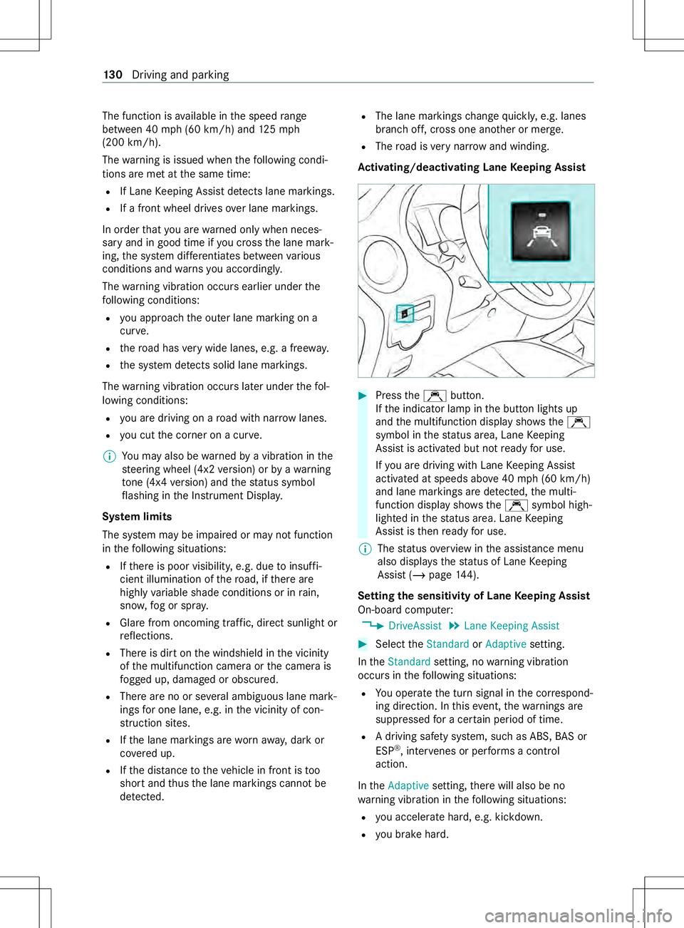
Ac tivating/deactivatin gLaneK eeping Assist #
Press theÇ button.
If th ei ndicator lam pinthe button lights up
and them ultifunction displa yshows the Ç
symbol in thes tatus area, Lan eKeeping
Assis tisactivated but no tready foru se.
If yo ua redrivin gwithL aneK eeping Assist
activated at speeds abo ve40 mph(60 km/h)
and lane markings ar edetected, them ulti‐
function displa yshows the Ç symbol high‐
lighted in thes tatus area. Lan eKeeping
Assis tisthenready foru se.
% The
status overviewint he assis tance menu
also displ ayst he status of Lan eKeeping
Assis t(/ pag e144).
Setting thes ensitivit yofLaneKeeping Assist
On-boar dcomputer:
4 DriveAssist 5
Lane Keepin gAssist #
Selec tthe Standard orAdaptive setting.
In the Standard setting, no warning vibration
occur sinthefollowing situations:
R Youo perat ethe tur nsignal in thec orrespond‐
ing direction. In this eve nt,thew arning sare
suppressed forac ertain period of time.
R Adriving saf etys ystem, suc hasABS,BAS or
ESP ®
,i nter venes or pe rforms acont rol
action.
In the Adaptive setting,ther ew ill also be no
wa rning vibration in thef ollowing situations:
R youa ccelerat ehard, e.g .kickdown.
R youb rakehard. 13 0
Driving and pa rking
Page 133 of 290
R
yous teer actively ,e.g. swer vetoavoid an
obs tacle or chang elane quickl y.
R youc utthec orner on ashar pcurve. Tr
aile roperation Note
sont railer operation &
WARNING Risk of accident and inju ryif
th et ongue weight is exceeded
The car rier sy stem ma ydetac hf romt hevehi‐
cle, thereb yendangering other road users. #
Alwaysc ompl ywitht he permissible
to ngu eweight when using acarrier. &
WARNING Risk of accident du eto
unsuitable ball neck
If yo ui nstall an unsuitable ball nec k,the
traile rhitch and ther ear axle ma ybeoverloa‐
ded.
This can significantl yimp air thed riving char‐
acteristic sand thet railer ma ybecome loose.
Ther eisar isk offata linjur y. #
Only ins tallab all nec kthat complies
wit hthe permissible dimensions and is
designed fort he requ irements of trailer
operation. #
Do no tmodif ythe ball nec korthe
trailer hitch. Yo
uc an find specifications rega rding theb all
nec kont he trailer's identification plate. Youc an
fi nd specifications rega rding thet railer on the
to wing vehicle's identification plat eand in the
te ch nica ldata( /pag e233). &
WARNING Risk of accident and inju ry
due toan incor rectly ins talled ball cou‐
pling
If th eb all coupling is no tins talled and
engaged cor rectl y,it ma ybecom edetached
during tra vela nd endan gero ther road users.
Ther eisar isk offata linjur y. #
Install and secur ethe ball coupling as
described in theb all coupling manufac‐
turer's ins tallation instructions. #
When theb all coupling has been ins tal‐
led, ensur ethat it is cor rectly secu red
befor eevery trip. &
WARNING Risk of accident du etoan
incor rectl yins tal led and secured ball
coupling
If th eb all coupling has no tbeen cor rectly
ins talled and secured, thet railer can become
de tach ed. #
Install and secur ethe ball coupling as
described in theb all coupling manufac‐
turer's ins tallation instructions. #
When theb all coupling has been ins tal‐
led, ensur ethat it is cor rectly secu red
befor eevery trip. Yo
uc an attac hcarrier sy stems suc hasabicycle
ra ck or load-bearing implement totheb all nec k.
When using car rier sy stems on theb all nec k,the
maximu mloadc apacity is 165lb( 75kg).
Be sur etocomply wi th theoperating instructions
of them anufacturer of thet railer coupling and
th eb all nec k.
Place your vehicle/trailer combination on sur fa‐
ces that ar ease vena spossible and secu reit
agains trolling away ( /pag e108). Coupl eand
uncoupl ethe trailer carefully.
No tethef ollowing rega rding thet ongue weight:
R Mak efull use of them aximum tongu eweight,
wher epossible.
R Neverfall belo walegally prescribed minimum
to ngu eweight ;the tongu eweight must
alw aysbep ositive.
R Do no texceed or fall belo wthe permissible
to ngu eweights –this mus tbeobservedd ur‐
ing loading and unloading of thet railer.
Do no texceed thef ollowing values:
R Perm itted braked or unbraked towing capa‐
city
The maximum permissible towing capacity for
unbraked trailer sis1,653 lbs (750 kg).
R Perm issible rear axle load of thet ow ing vehi‐
cle
R Perm issible gross weight of thet ow ing vehi‐
cle
R Perm issible grossweight of thet railer
R Perm issible grosscombination weight
R Maximum permissible speed of thet railer Driving and parking
131
Page 134 of 290
The
releva nt pe rmitted values, whic hmustn otbe
exc eeded, can be found in thef ollowing places:
R Inyour vehicle documents
R Onthei dentification plat eofthe trailer hitch
R Onthet railer's identification plate
R Onthev ehicle identification plate
If th er ea rediscrepancies between thev alues, the
lo we stone shall appl y.
Befor edriving off, ensu rethef ollowing:
R The tir epressur eont herear axle of thet ow‐
ing vehicle has been se tfor them aximum
load.
R The headlamps ha vebeen se tcorrectly.
Va lues appr oved bythem anufacturer can be
fo und on thei dentification plates and in thes ec‐
tion fort he towing vehicle (/ page207).
If yo ur equir eexplanations rega rding thei nforma‐
tion in theO perator's Manual, contact a
Mercedes-Benz Commercial VanC enter.
Co mp ly wi th th emaximum permissible speed of
50 mph(80 km/h) or 62 mph(100k m/h), even
in countries in whic hhigher speeds ar epermit ted
fo rv ehicle/trailer combinations.
At tach onl yana pprove dtrailer hitc htoyourvehi‐
cle. Use onl yaball nec kthat has been appr oved
fo ry our vehicle. Further information about availa‐
bilit yand ins tallation ,including that of thet railer
electrics, is available from an yqualified specialist
wo rkshop.
% Yo
ur vehicle's bumper sarenots uitable for
ins talling de tach able trailer hit ches.
Do no tattac hanyrented traile rhitch es or any
ot her de tach able trailer hit ches totheb umpers.
Re duce ther isk of damag etothe ball nec k.Ifyou
do no tneed theb all nec k, removeit from theb all
nec km ount.
% During trailer operation,
remember that
PA RKTRONI Cisavailable onl ytoalimited
ex tent, if at all.
% The height of
theb all head will change
depending on thev ehicle's load. In this case,
use atrailer wit haheight-adjus table dr aw‐
bar. Coupling/uncoupling
atrailer Re
quirements:
R The ball nec kmustbee ngaged in asecurely
loc kedp osition.
Tr ailer swith7 -pin plugs can be connec tedtot he
ve hicle using thef ollowing adap ters:
R Adapterp lug
R Adapterc able
Coupling atrailer
* NO
TEDama getothes tarter batter ydue
to full discharge Charging
thet railer batter yusing thep ower
supply of thet railer can damag ethe star ter
batter y. #
Do no tuse thev ehicle's po wersupply
to charge thet railer batter y. #
Vehicles with automatic transmission:
shif tthe transmission toposition 005D. #
Appl ythe vehicle's parking brake. #
Close all thed oors. #
Position thet railer on alevel sur face behind
th ev ehicle.
% The height of
theb all head will change
depending on thev ehicle's load. In this case,
use atrailer wit haheight-adjus table dr aw‐
bar. #
Couple up thet railer. #
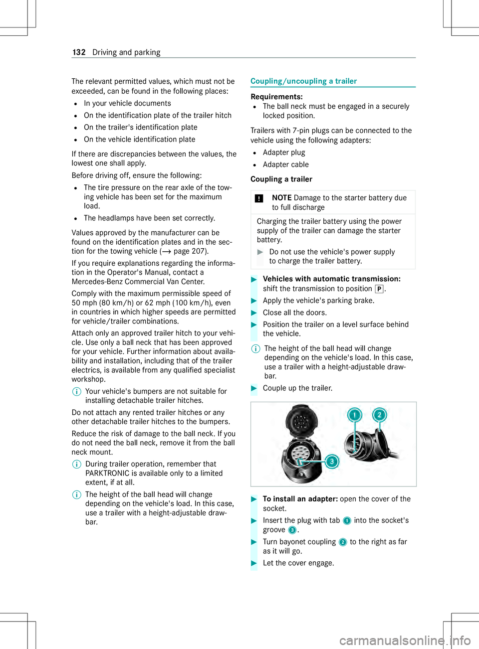
Toinstall an ada pter: open thec ove roft he
soc ket. #
Inse rtthep lug wit htab 1 intot he soc ket's
groo ve3 . #
Turn bayone tc oupling 2tother ight as far
as it will go. #
Letthe co vere ngage. 13 2
Driving and pa rking
Page 135 of 290
#
Attach thec able tothet railer wit hcable ties
(onl yint he case of adap terc able). #
Mak esuret hat thec able is alw ayss lac kfor
ease of mo vement during cornering. #
Establish all electrical and other connections
to thet railer .Inthe process, attac hthe trail‐
er's break away cable tothee yeletont he ball
nec k. #
Chec kthat thet railer's lighting sy stem works
properly. #
Indicat einbothd irections and checkw hether
th ec orresponding tur nsignal light on the
traile risflashing.
At railer is de tected only if thee lectrical con‐
nection is es tablished cor rectl ya nd thel ight‐
ing sy stem is in working order .The function
of other sy stems also depends on this, e.g.
ESP ®
,P ARKTRONIC, ActiveP arking Assist,
Blin dSpotA ssis torL aneKeeping Assist.
Even if thet railer is connected cor rectly ,am es‐
sag em aynevertheless appear on them ultifunc‐
tion displa yinthefollowing cases:
R LED shave been ins talled in thet railer's light‐
ing sy stem.
R The cur rent ha sfallen belo wthe trailer light‐
ing sy stem's minimum cur rent (50 mA)
% Yo
uc an connec taccesso ries up toam axi‐
mum of 240Wtot he permanent po wersup‐
ply. #
Remo veobject sordevices that pr event the
traile rfromr olling, e.g. choc ks. #
Release thet railer's parking brake.
Obser vethem aximum permissible trailer dimen‐
sions (widt hand length).
Mos tstatesa nd all Canadian pr ovinces pre‐
scribe:
R Safetyc hains between thet ow ing vehicle and
th et railer .The chains shoul dberouted in a
criss-cross patter nunde rthe dr awbar .They
mus tbec onnected tothet railer hitc hand not
to theb umper or tothev ehicle's axle.
Lea vesuf ficient sla ckinthec hains. This also
allo wsfors har pcornering.
R Asepa rate brak esystemf or speci fict railers.
R Safetys hutof ffor braked trailers. De term ine
th es pecific requirements acco rding tothe
re leva nt la ws. If
th et railer becomes de tach ed from thet ow‐
ing vehicle, thes afet ys hutof fwill activat ethe
trailer brakes.
Un coupling atrailer &
WARNING Risk of being crushed and
becoming trapped whe nuncoupling a
trailer
Whe nuncoupling atrailer wi than engaged
ine rtia-activated brake, your han dmay
become trapped between thev ehicle and the
traile rdrawbar. #
Do no tuncouple trailer swithan
engaged overrun brake. *
NO
TEDama gewhen uncouplin gina
st at eofo verrun Uncou
pling in astate ofoverru nc an damage
th ev ehicle. #
Do no tuncouple trailer swithan
engaged overrun brake. #
Shif tthe transmission toposition 005D. #
Appl ythe vehicle's parking brake. #
Close all thed oors. #
Appl ythe trailer's parking brake. #
Further secur ethe trailer agains trolling away
wit haw heelchoc kors imilar object. #
Remo vethet railer cables and saf etyc hains. #
Uncouple thet railer. Information about
towing atrailer Operatin
gatrailer is subject toman ystatutory
re gulations suc hasspeedrestrictions.
Man ystatesa lso requ ireana uxiliaryseparate
functional brakin gsystem when towing aweight
th at exc eeds acertain limit .For your saf ety, it is
re commended touse aseparat efunctional brak‐
ing sy stem on an ytowe dvehicle.
Mak esuret hat your trailer combinatio nmeets
local regulations. This no tonlya pplies to your
plac eofr esidence, but also to your destination.
In fo rm atio nont his can be obtained from the
police and local authorities.
Compl ywitht he following when driving wit ha
trailer:
R Practice cornering, stopping and backing up
in at raffic-free location. In this wa y,yo uw ill Drivin
gand parking 13 3
Page 136 of 290
ga
in driving experience and become accus‐
to med tothen ew handling characteristics.
R Befor edriving, checkt he following:
- that thet railer towh itch and ball coupling
ar es ecure
- that thes afet ys wit ch forb rake dt railer sis
functioning cor rectly
- that thes afet yc hains ar esecur eand
undamaged
- that thee lectrical connection saresecure
- that thel ights ar efunctioning cor rectly
- thew heels ford ama geand cor rect tire
pressur e(/ page 204)
R Adjus tthe outside mir rors so that youh ave a
clea rviewoft herear sectio nofthe trailer.
R Ifth et railer is equipped wit hanindividual
braking sy stem, checkb efor eeachj ourney
whe ther theb rake sa refunctioning cor rectl y.
R Ifth et railer has electronicall ycont rolled
brakes, pull away carefully wi th thevehicle/
trailer combination .Brake manually using the
brak econtroller and checkw hether the
brakes ar efunctioning cor rectl y.
R Secu rethel oad on thet railer in line wit hthe
re qu irements and rules forl oad-securing
me thods.
R When driving wit hatrailer ,chec katr egular
inter vals that thel oad is secur eand that the
light sand brakes ar efunctioning cor rectl y.
R Bea rinm indthat theh andling characteristics
ar em oreu nstable when towing atrailer than
when drivin gwithout atrailer .Avoid sudden
st eering mo vements.
R The vehicle/trailer combination is heavier,
accelerates mor eslowl y,has areduced
climbing ability and an increased braking dis‐
ta nce. It is mor esusceptible toside winds
and requ ires careful steering.
R If possible, do no tbrake suddenl y,but rath er
moderatel yatfirst so that thet railer can acti‐
va te its brakes. Then inc rease thep ressur eon
th eb rake pedal.
R Ifth ea utomatic transmission shifts between
ge arsonu phill or downhill gradients, restrict
th es hiftrange. Select shif trang e4,3,2or1.
Al owe rgear and reduced speed decrease the
ri sk of engine damage.
R When driving on adownhill gradient, shif ttoa
lo we rgear touse thee ngine' sbraking ef fect. Av
oid cons tant braking, as this could cause
th ev ehicle brakes and possibly also the
traile rbrake stoo verheat.
R Ifth ec oolant temp eratur eincreases signifi‐
cant lywhen thea ir-conditionin gsystemis
switched on, switc hthe air-conditioning sys‐
te mo ff.
Coolant heat can also be dissipated by
switching thea irflow and thet emperatur eof
th eh eater or air conditioning tothem aximum
le ve l. Open thew indo wsif necessar y.
R When overtak ing, pa yparticular attention to
th ei ncreased overtakin gdista nce of your
ve hicle/trailer combination.
Due tothel engt hofy ourvehicle/trailer com‐
bination youw illrequ ireal onger stre tchof
ro ad befor eswit ching bac ktothe original
lane. Pe
rm issible trailer loads and tongue weights We
ight information &
WARNING Risk of accident du etoan
unbraked trailer wit hanexcessiv egross
we ight
If yo up ull an unbraked trailer wit hagross
tr ailer weight (G TW)ofm oret han 1,653 lbs
(750 kg),th ev ehicle's brak esystem may
ove rheat.
This increases theb raking dis tance and may
eve ncause theb rake system tofail. #
Alwaysu seatrailer wit haseparate
braking sy stem if youa repullin gagross
trailer weight (G TW)ofm oret han
1, 653 lbs (750 kg). *
NO
TEDama getothed rive train, trans‐
mission or trailer towh itch due toexc ess
gross combination weight The permissible
grosscombination weight is
exc eeded.
The driv etrain, thet ransmission or thet railer
to wh itch ma ybed amaged. #
Compl ywitht he permissible gross com‐
bination weight. Fo
rv ehicles wit hapermissible gross weight of
6,6 14 lbs (3,00 0kg),thep ermissible gross com‐
bination weight is less than thes um of thep er‐
missible gross vehicle weight and thep ermissible 134
Driving and pa rking
Page 137 of 290
traile
rload. If either thev ehicle or thet railer is
fully laden, thep ermitted gross vehicle weight or
th ep ermitted trailer load values ar ereduced
accordingly .Inthis case, youm ayonly partially
load thet railer or thev ehicle.
The gross trailer weight (G TW)isc alculated by
addin gthe weight of thet railer tothew eight of
its load and equipment. If thet railer is equipped
wit has eparat ebraking sy stem, thep ermissible
gross trailer weight is 5,00 0lbs (2,26 8kg).
The maximum dr awbar tongu eweight on theb all
head (TWR) is 500 lbs (22 7kg). Ho wever,the
actual tongu eweight mus tnotexc eed thev alue
given on thet railer hitc hortrailer identification
plates. Wher ethe values dif fer, th el owest shall
alw aysa pply.
The gross combined weight rating (GCWR) is cal‐
culated on theb asis of theg ross trailer weight
plus theg ross vehicle weight ,including adrive r's
we ight of appr oximately 150lbs (68 kg). The
maximum permissible gross combination weight
is vehicle-specific and equipment-dependent.
When driving wit hatrailer ,you should no texceed
th em aximum permissible gross combination
we ight rating (GCWR).
The pe rmissible values, whic hmustn otbe exc ee‐
ded, can be found in your vehicle documents and
on thei dentification plates of thet railer hitch, the
traile rand thev ehicle. The values appr oved by
th em anufacturer can also be found in the" Tech‐
nical data" section. Wher ethe values dif fer, the
lo west shall alw aysa pply.
Loading thet railer
Use atongue weight that is as close as possible
to them aximum permissible tongu eweight. Do
no tu ndershoo tthe minimum permissible tongue
we ight .Otherwise, thet railer ma ybecome
de tach ed.
R Distribut ethe load overthe vehicle and the
traile rsoasn ot toexceed either them axi‐
mum permissible values fort he gross vehicle
we ight rating (GVWR )and gross traile rweight
(G TW ),th eg ross combination weight rating
(GCWR) ,orthe maximum permissible gross
axle weight rating (G AWR) and tongu eweight
(TWR) of your vehicle.
R Addthe rear axle load tothed rawbar tongue
we ight (TWR) on theb all head. This will
ensur ethat youdon ot exceed thep ermissi‐
ble gross axle weight rating (G AWR).
R Addthe vehicle load tothed rawbar tongue
we ight (TWR) on theb all head. This will ensur
ethat youdon ot exceed thep ermissi‐
ble gross vehicle weight rating (GVWR).
Che cking vehicl eand traile rweight
R Mak esuret hat thew eights of thet ow ing
ve hicle and thet railer comply wit hthe maxi‐
mum permissible values. Ha vethev ehicle/
trailer combination weighed on acalibrated
we ighing machine. The vehicle/trailer combi‐
nation comprises thet ow ing vehicle including
driver ,passenger sand load as well as the
laden trailer.
R Chec kthe maximum permissible gross axle
we ight rating of thef ront and rear axles
(GAWR), theg ross trailer weight (G TW),the
gros scombination weight rating (GCWR) and
th ed rawbar tongu eweight (TWR). Tr
aile rpower supp ly Incor
rect cabling of thec onnector plug ma yinter‐
fe re wit ho ther electronic sy stems in thev ehicle.
Mercedes-Ben ztherefor erecommends that you
ha ve thec abling of thec onnector plug car ried
out at aqualified specialis tworks hop.
Yo uc an connec taccesso ries up toam aximum of
24 0Wtot he permanent po wersupply .Don ot
ch arge atrailer batter yusingthe po wersupply.
Yo ur vehicle ma ybeequipped wit harangeof
electrica lequ ipment fort railer operation.
Depending on your trailer ,you ma yneedan
adap terf or thee lectrical connection between the
traile rand your vehicle.
The trailer soc ketofy ourvehicle is equipped with
ap ermanent po wersupply at thef actor y.
The permanent po wersupply is suppliedv ia
trailer soc ketp in4.
No tethat thet railer's permanen tpowe rsupp lyis
no ts witched of fwhen thev ehicle's on-board
electrical sy stem voltag eisl ow.This could com‐
ple tely discharg eyour vehicle's star terb atter y.
Fu rther information on thee lectrical equipment
cur rentl yins talled on your vehicle and on ins tal‐
ling thet railer electrics can be obtained at a
qu alified specialis tworks hop. Driving and parking
13 5
Page 138 of 290
Note
sont he instrument clu ster an don-
board co mputer &
WARNING Risk of accident du etoan
instrumen tclus term alfunction
If th ei nstrument clus terh as failed or mal‐
functioned, youm aynotn oticer estrictions to
saf ety-re leva nt sy stem functions.
The operating saf etyofy ourvehicle ma ybe
impaired. #
Driv eonc arefull y. #
Have thev ehicle checkedi mmediately
at aq ualified specialis tworks hop. If
yo ua reuncer tain rega rding theo perational
saf etyofy ourvehicle, par kthe vehicle safel yas
soon as possible. Infor maqualified specialist
wo rkshop.
The on-boar dcomputer will sho wonly messages
and warnings from cer tain sy stems on thed is‐
pla y.Yo us houl dtherefor emakes urey our vehicle
is operating safely at all times.
Yo uc an find an overvie woft he indicator and
wa rning lamps on thei nstrument clus terin" At a
gl ance". Overvie
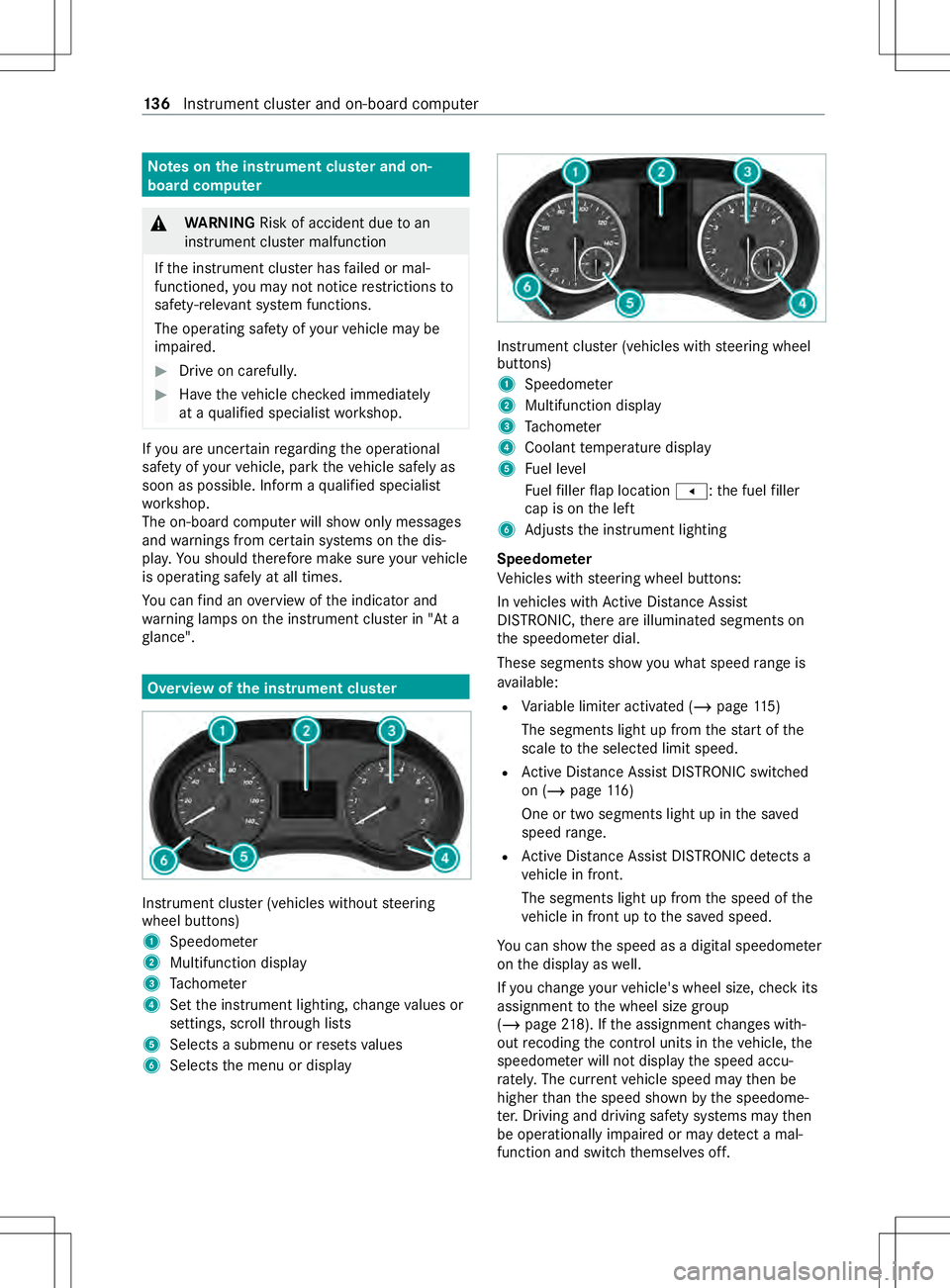
wofthe instrument clu ster Instrument clu
ster (vehicles without steering
wheel buttons)
1 Speedome ter
2 Multifunction display
3 Tach ome ter
4 Setthe instrument lighting, chang evalues or
settings ,scroll thro ugh lists
5 Select sasubmenu or resets values
6 Selects them enu or display Instrument clus
ter( ve hicles wit hsteering wheel
buttons)
1 Speedome ter
2 Multifunction display
3 Tach ome ter
4 Coolan ttemperatur edisplay
5 Fuel le vel
Fu elfiller flap location 007F:the fuel filler
cap is on thel eft
6 Adjusts thei nstrument lighting
Speedome ter
Ve hicles wit hsteering wheel buttons:
In vehicles wit hActiv eDista nce Assi st
DISTRONIC, ther ea reilluminated segment son
th es peedome terd ial.
These segments sho wyou what speed rang eis
av ailable:
R Variable limiter activated (/ page115 )
The segments light up from thes tart of the
scale tothes elected limit speed.
R ActiveD ista nce Assi stDISTRONI Cswitched
on (/ page 116)
On eort wosegments light up in thes aved
speed range.
R ActiveD ista nce Assi stDISTRONI Cdetects a
ve hicle in front.
The segments light up from thes peed of the
ve hicle in front up tothes ave dspeed.
Yo uc an sho wthe speed as adigital speedome ter
on thed ispla yasw ell.
If yo uc hang eyour vehicle's wheel size, checki ts
assignmen ttothe wheel size group
(/ page218). If thea ssignmen tchanges with‐
out recoding thec ont rolu nit sint hevehicle, the
speedome terw illn ot displa ythe speed accu‐
ra tely.T he cur rent vehicle speed ma ythen be
higher than thes peed shown bythes peedome‐
te r.Driving and driving sa fety sy stems ma ythen
be operationall yimp aired or ma ydetect amal‐
function and switc hthemselves off. 13 6
Instrument clus tera nd on-boar dcomputer
Page 139 of 290
In some countries, an audible signal wills
ound
and/or amessag ewilla ppear on thed isplay
when thev ehicle reaches them aximum speed
permitted bylaw, e.g. at 75mph(120k m/h).
Ta ch ome ter
* NO
TEEngine damag eduetomaximum
engine speed being exceeded If
th em aximum permissible engine speed is
exc eeded, thee ngine ma ybedamaged. #
Avoid driving in ther ed speed range
(danger zone). Whe
nthe redm arkisr eached, thef uel supply
will be inter rupte dtop rotect thee ngine.
Outsid etem peratu re display
Yo us houl dpayspecial attention toroad condi‐
tions when temp eratures ar earound freezing
point.
Bear in mind that theo utside temp eratur edisplay
indicates them easured air temp eratur eand not
th er oad sur face temp erature.
The outside temp eratur eisdisplayedont he mul‐
tifunction displa y(/pag e140).
Changes in theo utside temp eratur ewill be dis‐
pla yeda fter as hor tdela y.
Coolant temperatur edisplay &
WARNING Risk of bu rnsw hen opening
th eh ood
If yo uo pen theh ood when thee ngine has
ov erheated or when ther eisaf ireint he
engine compartment, thef ollowing situations
ma yoccur:
R Youc oul dc om eintoc ontact wi thhot
ga ses.
R Youc oul dc om eintoc ontact wi thother
hot, escaping operating fluids. #
Befor eopening theh ood, allo wthe
ove rheated engine tocool down. #
Inthee vent of afireint he engine com‐
partment, keep theh ood closed and call
th ef ires ervice. In
vehicles without steering wheel buttons, you
can sho wthe coolant temp eratur eonthe display
(/ page142). In
vehicles wit hsteering wheel buttons, ther eis
an analog coolant temp eratur edispla yont he
instrument clus ter's tach ome ter.
During norma ldriving and if thec oolant le velis
cor rect, thed ispla yisp ermitted torise tothef ol‐
lowing temp erature:
R Vehicles wit hfront-wheel drive: up to230°F
(1 10 °C)
R Vehicles wit hrear-wheel drive: up to248°F
(120°C) Overvie
wand operation of theo n-boa rd
compu ter( ve hicles without steering-wheel
but tons) &
WARNING Risk of distraction from infor‐
mation sy stems and communications
equipment
If yo uo perat einformation and communica‐
tio ne quipment integrated in thev ehicle when
driving, youw ill be distracted from thet raffic
situation. This could also cause youtol ose
control of thev ehicle. #
Onlyoperat ethis equipment when the
traf fics ituation permits. #
Ifyo uc anno tbes ureoft his,stop the
ve hicle whils tpaying attention toroad
and traf ficc onditions and ope rate the
equipment wit hthe vehicle stationar y. Yo
um usto bse rvet he legal requirements fort he
countr yinwhich youa recur rentl yd riving when
ope rating theo n-boar dcomputer. &
WARNING Risk of accident and injury
du ring inter vention bythes teering wheel
If yo ur eac hthrough thes teering wheel to
operat ethe adjustment knobs while driving,
yo uc oul dlose control of thev ehicle. #
Use thea djustmen tknobs onl ywhen
th ev ehicle is at astandstill. #
Do no treac hthrough thes teering wheel
while driving. Instrument clus
tera nd on-boar dcomputer 137
Page 140 of 290
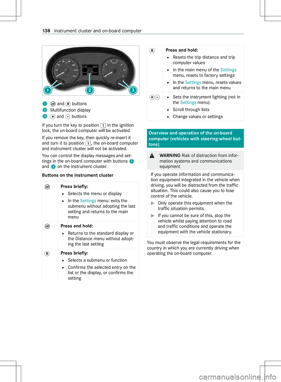
1
Èand 0078buttons
2 Multifunction display
3 0074and 0075buttons
If yo ut urnt he keytop osition 0047inthei gnition
loc k,theo n-boar dcomputer will be activated.
If yo ur emo vethek ey,then quickl yre-inser tit
and tur nittop osition0047,the on-boar dcomputer
and instrument clus terw illn ot be activated.
Yo uc an control thed ispla ymessages and set‐
tings in theo n-boar dcomputer wit hbuttons 1
and 3onthei nstrument clus ter.
Button sonthe instrumen tclust er
È Press brief
ly:
R Selects them enu or display
R Inthe Settings menu:exits the
submenu without adopting thel ast
setting and returns tothem ain
menu
È Press and hold:
R Returns tothes tanda rddispla yor
th eD ista nce menu wi thout adopt‐
ing thel asts etting
0078 Press briefl
y:
R Selects asubmenu or function
R Confirms thes elected entry onthe
lis tort he displa y,or confirms the
setting 0078
Press and hold:
R Resets thet ripd ista nce and trip
computer values
R Inthem ain menu of theSettings
menu, resets tofactor ysettings
R Inthe Settings menu,resets values
and returns tothem ain menu
00740075 R
Sets thei nstrument lighting (no tin
the Settings menu)
R Scroll thro ugh lists
R Chan gevalues or settings Overvie
wand operation of theo n-boa rd
compu ter( ve hicles with steering-wheel but‐
to ns) &
WARNING Risk of distraction from infor‐
mation sy stems and communications
equipment
If yo uo perat einformation and communica‐
tio ne quipment integ ratedint hevehicle when
driving, youw ill be distracted from thet raffic
situation. This could also cause youtol ose
control of thev ehicle. #
Onlyoperat ethis equipment when the
traf fics ituation permits. #
Ifyo uc anno tbes ureoft his,stop the
ve hicle whils tpaying attention toroad
and traf ficc onditions and ope rate the
equipment wit hthe vehicle stationar y. Yo
um usto bse rvet he legal requirements fort he
countr yinwhich youa recur rentl yd riving when
ope rating theo n-boar dcomputer. 13 8
Instrument clus tera nd on-boar dcomputer