coolant temperature MERCEDES-BENZ ML320 1997 Complete Repair Manual
[x] Cancel search | Manufacturer: MERCEDES-BENZ, Model Year: 1997, Model line: ML320, Model: MERCEDES-BENZ ML320 1997Pages: 4133, PDF Size: 88.89 MB
Page 3858 of 4133

vehicles delivered from 6/00 is increased for the driving mode selected by about 100 rpm when the switch-on
threshold of about 900 rpm is exceeded. This increase is cancelled again when the external temperature drops
below 32° C.
Undervoltage
If the engine control unit detects an undervoltage the idling speed is increased until the ignition is switched off
for the driving mode selected by about 100 rpm.
If the control unit SBC reports an undervoltage to the engine control unit over CAN the idling speed for the
driving mode selected is increased to about 750 rpm.
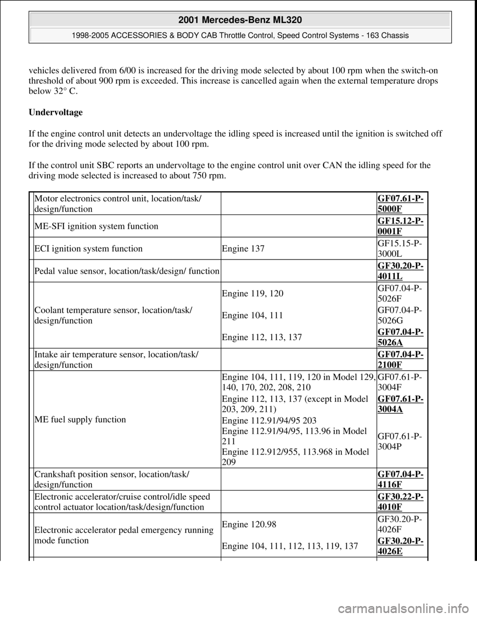
Motor electronics control unit, location/task/
design/function GF07.61-P-
5000F
ME-SFI ignition system function GF15.12-P-
0001F
ECI ignition system functionEngine 137GF15.15-P-
3000L
Pedal value sensor, location/task/design/ function GF30.20-P-
4011L
Coolant temperature sensor, location/task/
design/function
Engine 119, 120GF07.04-P-
5026F
Engine 104, 111GF07.04-P-
5026G
Engine 112, 113, 137GF07.04-P-
5026A
Intake air temperature sensor, location/task/
design/function GF07.04-P-
2100F
ME fuel supply function
Engine 104, 111, 119, 120 in Model 129,
140, 170, 202, 208, 210GF07.61-P-
3004F
Engine 112, 113, 137 (except in Model
203, 209, 211)GF07.61-P-
3004A
Engine 112.91/94/95 203
Engine 112.91/94/95, 113.96 in Model
211
Engine 112.912/955, 113.968 in Model
209
GF07.61-P-
3004P
Crankshaft position sensor, location/task/
design/function GF07.04-P-
4116F
Electronic accelerator/cruise control/idle speed
control actuator location/task/design/function GF30.22-P-
4010F
Electronic accelerator pedal emergency running
mode functionEngine 120.98GF30.20-P-
4026F
Engine 104, 111, 112, 113, 119, 137GF30.20-P-
4026E
2001 Mercedes-Benz ML320
1998-2005 ACCESSORIES & BODY CAB Throttle Control, Speed Control Systems - 163 Chassis
me
Saturday, October 02, 2010 3:36:27 PMPage 18 © 2006 Mitchell Repair Information Company, LLC.
Page 3861 of 4133

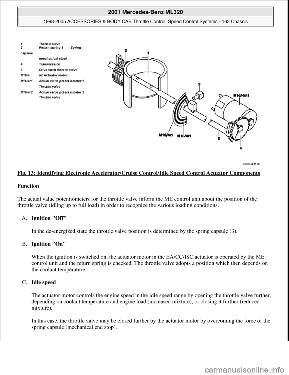
Fig. 13: Identifying Electronic Accelerator/Cruise Control/Idle Speed Control Actuator Components
Function
The actual value potentiometers for the throttle valve inform the ME control unit about the position of the
throttle valve (idling up to full load) in order to recognize the various loading conditions.
A.Ignition "Off"
In the de-energized state the throttle valve position is determined by the spring capsule (3).
B.Ignition "On"
When the ignition is switched on, the actuator motor in the EA/CC/ISC actuator is operated by the ME
control unit and the return spring is checked. The throttle valve adopts a position which then depends on
the coolant temperature.
C.Idle speed
The actuator motor controls the engine speed in the idle speed range by opening the throttle valve further,
depending on coolant temperature and engine load (increased mixture), or closing it further (reduced
mixture).
In this case, the throttle valve may be closed further by the actuator motor by overcoming the force of the
sprin
g capsule (mechanical end stop).
2001 Mercedes-Benz ML320
1998-2005 ACCESSORIES & BODY CAB Throttle Control, Speed Control Systems - 163 Chassis
me
Saturday, October 02, 2010 3:36:27 PMPage 21 © 2006 Mitchell Repair Information Company, LLC.
Page 3961 of 4133

AD54.30-P-5000-02A
Display instruments controlled via CAN
troubleshooting chart IC
The following display instruments or indicator lamps/ malfunction
indicator lamps receive their information from the traction system
control module (N47) via CAN data buses (an appropriate message
appears in the display on vehicles with multi-function display):
D
Total mileage recorder, trip odometer
D
Electronic speedometer
D
Low brake fluid level/parking brake indicator lamp (except model 163
parking brake indicator lamp only via CAN)
D
Brake pad wear indicator lamp
D
ABS MIL
D
ETS, ASR, ESP indicator lamp
D
ETS, ASR, ESP malfunction indicator lamp
Model 163 only:
The
"Low-Range"
indicator lamp receives its information from the
transfer case control module (N78) via CAN data buses.
The
"Fog lamps"
indicator lamp (only model 163 except
I
) receives
its information from the All-activity module (AAM, N10) via CAN data
buses.
Model 168 only:
The
" Gear indicator "
indicator lamp receives its information from the
gear recognition module (A61) or from automatic clutch control module
(N15/4) via CAN data buses.
The following display instruments or indicator lamps/
malfunction indicator lamps receive their information from the
injection system control module (N3) via CAN data buses (an
appropriate message appears in the display on vehicles with
multi-function display):
D
Tachometer
D
Low engine oil level lamp
D
Engine coolant temperature
D
Preglow indicator lamp (diesel only)
D
Vehicle speed warning
D
Vehicle speed limit warning
D
Severe leak warning (
I
only), the fuel reserve indicator lamp
(A1e4) flashes
D
Active Service System (ASSYST):
D
Oil condition
D
Oil level
D
Oil temperature
D
Mass volumetric efficiency (load moment)
D
Engine speed, engine coolant temperature
Copyright DaimlerChrysler AG 05.06.2006 CD-Ausgabe G/10/04 . This WIS print-out will not be recorde
d by Modification services.
Page 1