air filter MERCEDES-BENZ ML320 1997 Complete User Guide
[x] Cancel search | Manufacturer: MERCEDES-BENZ, Model Year: 1997, Model line: ML320, Model: MERCEDES-BENZ ML320 1997Pages: 4133, PDF Size: 88.89 MB
Page 1162 of 4133
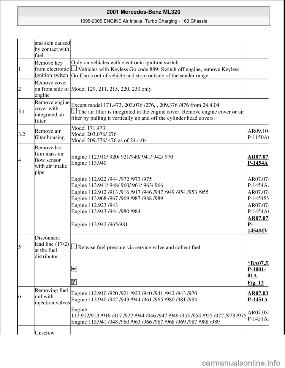
and skin caused
by contact with
fuel
1
Remove key
from electronic
ignition switchOnly on vehicles with electronic ignition switch.
Vehicles with Keyless Go code 889: Switch off engine, remove Keyless
Go-Cards out of vehicle and store outside of the sender range.
2
Remove cover
on front side of
engine
Model 129, 211, 215, 220, 230 only
3.1
Remove engine
cover with
integrated air
filterExcept model 171.473, 203.076 /276, , 209.376 /476 from 24.4.04
The air filter is integrated in the engine cover. Remove engine cover or air
filter by pulling it vertically up and off the cylinder head covers.
3.2Remove air
filter housingModel 171.473
Model 203.076/ 276
Model 209.376/ 476 as of 24.4.04AR09.10-
P-1150AC
4
Remove hot
film mass air
flow sensor
with air intake
pipe
Engine 112.910/ 920/ 921/940/ 941/ 942/ 970
Engine 113.940AR07.07-
P-1454A
Engine 112.922 /944 /972 /973 /975
Engine 113.941/ 948/ 960/ 961/ 963/ 966AR07.07-
P-1454AA
Engine 112.912 /913 /916 /917 /946 /947 /949 /954 /953 /955
Engine 113.968 /967 /969 /987 /988 /989AR07.07-
P-1454SV
Engine 112.923 /943
Engine 113.943 /944 /980 /984AR07.07-
P-1454AG
Engine 113.942 /965/981
AR07.07-
P-
1454MV
5
Disconnect
lead line (17/2)
at the fuel
distributor
Release fuel pressure via service valve and collect fuel.
*BA07.52
P-1001-
01A
Fig. 12
6
Removing fuel
rail with
injection valvesEngine 112.910 /920 /921 /923 /940 /941 /942 /943 /970
Engine 113.940 /942 /943 /944 /961 /965 /980 /981 /984AR07.03-
P-1451A
Engine
112.912/913 /916 /917 /922 /944 /946 /947 /949 /953 /954 /955 /972 /973 /975
Engine 113.941 /948 /960 /963 /966 /967 /968 /969 /987 /988 /989AR07.03-
P-1451AA
Unscrew
2001 Mercedes-Benz ML320
1998-2005 ENGINE Air Intake, Turbo Charging - 163 Chassis
me
Saturday, October 02, 2010 3:16:57 PMPage 11 © 2006 Mitchell Repair Information Company, LLC.
Page 1556 of 4133
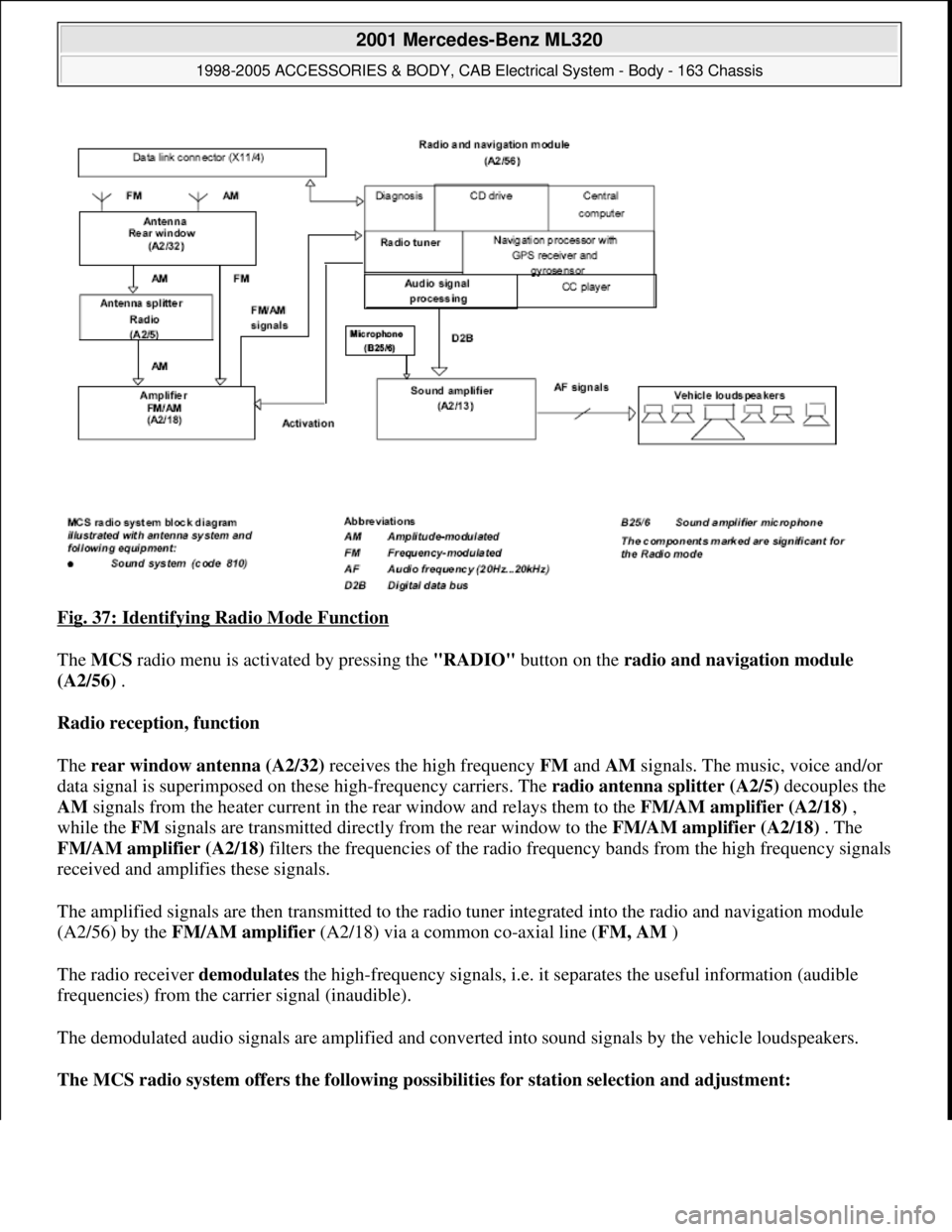
Fig. 37: Identifying Radio Mode Function
The MCS radio menu is activated by pressing the "RADIO" button on the radio and navigation module
(A2/56) .
Radio reception, function
The rear window antenna (A2/32) receives the high frequency FM and AM signals. The music, voice and/or
data signal is superimposed on these high-frequency carriers. The radio antenna splitter (A2/5) decouples the
AM signals from the heater current in the rear window and relays them to the FM/AM amplifier (A2/18) ,
while the FM signals are transmitted directly from the rear window to the FM/AM amplifier (A2/18) . The
FM/AM amplifier (A2/18) filters the frequencies of the radio frequency bands from the high frequency signals
received and amplifies these signals.
The amplified signals are then transmitted to the radio tuner integrated into the radio and navigation module
(A2/56) by the FM/AM amplifier (A2/18) via a common co-axial line (FM, AM )
The radio receiver demodulates the high-frequency signals, i.e. it separates the useful information (audible
frequencies) from the carrier signal (inaudible).
The demodulated audio signals are amplified and converted into sound signals by the vehicle loudspeakers.
The MCS radio system offers the following possibilities for station selection and adjustment:
2001 Mercedes-Benz ML320
1998-2005 ACCESSORIES & BODY, CAB Electrical System - Body - 163 Chassis
me
Saturday, October 02, 2010 3:30:05 PMPage 61 © 2006 Mitchell Repair Information Company, LLC.
Page 1608 of 4133
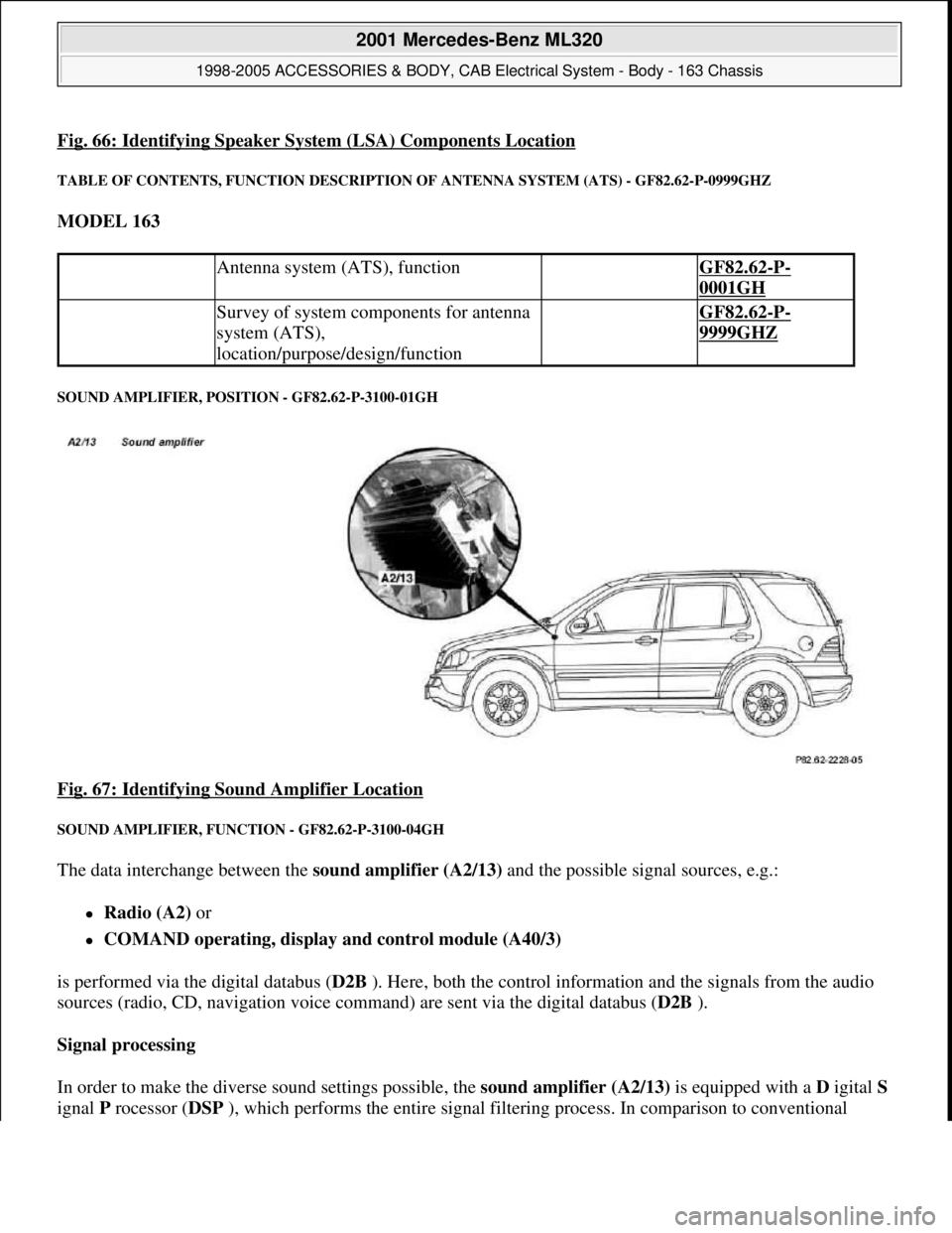
Fig. 66: Identifying Speaker System (LSA) Components Location
TABLE OF CONTENTS, FUNCTION DESCRIPTION OF ANTENNA SYSTEM (ATS) - GF82.62-P-0999GHZ
MODEL 163
SOUND AMPLIFIER, POSITION - GF82.62-P-3100-01GH
Fig. 67: Identifying Sound Amplifier Location
SOUND AMPLIFIER, FUNCTION - GF82.62-P-3100-04GH
The data interchange between the sound amplifier (A2/13) and the possible signal sources, e.g.:
Radio (A2) or
COMAND operating, display and control module (A40/3)
is performed via the digital databus (D2B ). Here, both the control information and the signals from the audio
sources (radio, CD, navigation voice command) are sent via the digital databus (D2B ).
Signal processing
In order to make the diverse sound settings possible, the sound amplifier (A2/13) is equipped with a D igital S
ignal P rocessor (DSP ), which performs the entire signal filtering process. In comparison to conventional
Antenna system (ATS), function GF82.62-P-
0001GH
Survey of system components for antenna
system (ATS),
location/purpose/design/function GF82.62-P-
9999GHZ
2001 Mercedes-Benz ML320
1998-2005 ACCESSORIES & BODY, CAB Electrical System - Body - 163 Chassis
me
Saturday, October 02, 2010 3:30:06 PMPage 113 © 2006 Mitchell Repair Information Company, LLC.
Page 1609 of 4133
analog filters, digital filters contain the following significant advantages:
the filter parameters (sound settings) do not alter throughout the period, this thus means that all the
settings can be repeated exactly
low noise level
the component outlay is significantly reduced, as the filter parameters are set by the software and not by
varying component values (resistances, capacitances or inductance values), thus the number of possible
filter settings is increased
Sound optimizations
Each of the six amplifier channels is equipped with an individual compensation, which can, when requested,
rectify the vehicle's acoustics. In addition further sound optimization settings can be made and effects such as,
e.g. 'voice emphasizing' or 'stereoscopic sound' invoked.
Bass, treble, volume, balance, fader and the dynamic loudness function can be individually set.
Noise suppression
The output level of the six 6 output stages is constantly monitored and regulated such that distortion is kept to a
minimum.
Automatic Vehicle Noise Compensation (VNC))
With the aid of the sound amplifier microphone (B25/6) , which is connected directly to the sound amplifier
(A2/13) , the noise level in the vehicle is measured. The volume of the music output signal is constantly adapted
to this noise level. To this end the sound amplifier (A2/13) must be able to detect which of the measured
signals are noise emissions from the moving vehicle and which are audio signals. This is conducted by
comparing the output signal of the sound amplifier (A2/13) with the measured signal.
Put simply, the vehicle noise level is the difference between the two signals.
Diagnosis
The sound amplifier (A2/13) can set up the following messages which are relevant for the diagnosis:
Operating status
Undervoltage
Internal fault in the sound amplifier (A2/13)
The messages are sent over the digital databus ( D2B ) to the COMAND operating, display and control
module (A40/3) or the radio (A2) , and can be read out there over the ( K-wire ) diagnostics line.
SOUND AMPLIFIER, LOCATION/TASK/DESIGN/FUNCTION - GF82.62-P-3100GH
MODEL 163 with CODE (810) sound system
2001 Mercedes-Benz ML320
1998-2005 ACCESSORIES & BODY, CAB Electrical System - Body - 163 Chassis
me
Saturday, October 02, 2010 3:30:06 PMPage 114 © 2006 Mitchell Repair Information Company, LLC.
Page 1610 of 4133
REAR WINDOW ANTENNAS, DESIGN - GF82.62-P-3106-03GH
Model 163
Antenna ranges
Sound amplifier,
position GF82.62-P-3100-
01GH
Sound amplifier, taskProcessing (sound settings)
and amplification of all audio
signals (radio, cassette, CD,
navigation voice command,..)
Sound amplifier, designDigital databus interface
(D2B)
Connection for sound
amplifier microphone
(B25/6) for automatic
vehicle noise
compensation
Digital filter technology
outputs distributed
across following
loudspeaker groups:
Treble
Medium treble
Medium bass
Bass
These are distributed as
follows:
Left front
Right front
Left rear
Rear right
Center
Woofer
Sound amplifier,
function GF82.62-P-3100-
04GH
2001 Mercedes-Benz ML320
1998-2005 ACCESSORIES & BODY, CAB Electrical System - Body - 163 Chassis
me
Saturday, October 02, 2010 3:30:06 PMPage 115 © 2006 Mitchell Repair Information Company, LLC.
Page 1666 of 4133
AM RADIO RECEPTION DIFFICULTIES - AF82.60-P-6005A
MODEL 163.136 /154 /172 ## up to 146760
Revisions
%.
Range of radio
remote control for
central locking
reduced by up 50 %
Non-metallized foil:
Only slight
reduction of
functions described
above.
01.09.99Supersedes STI no.
82.60-024 dated 01.09.99
CauseRemedy
Loss of noise filtering
function of the antenna
splitter (A2/5) and the
AM/FM amplifier
(A2/18) due to poor
ground connection.1 Remove AM/FM
amplifierAR82.62-P-8347GH
AM radio reception is
being adversely affected
by background noise and
electrical interference,
resulting in the station
signal being overridden.2 Remove antenna
splitterAR82.70-P-8953GH
The painted surface of the
vehicle's body, combined
with the protective
coating on the mounting
screws, may not provide
an adequate ground.3 Remove paint/E-
coating from vehicle
body at mounting points
of antenna splitter and
AM/FM amplifier
4 Remove protective
coating on shoulder of
antenna splitter and
amplifier mounting
screws
2001 Mercedes-Benz ML320
1998-2005 ACCESSORIES & BODY, CAB Electrical System - Body - 163 Chassis
me
Saturday, October 02, 2010 3:30:07 PMPage 171 © 2006 Mitchell Repair Information Company, LLC.
Page 1882 of 4133
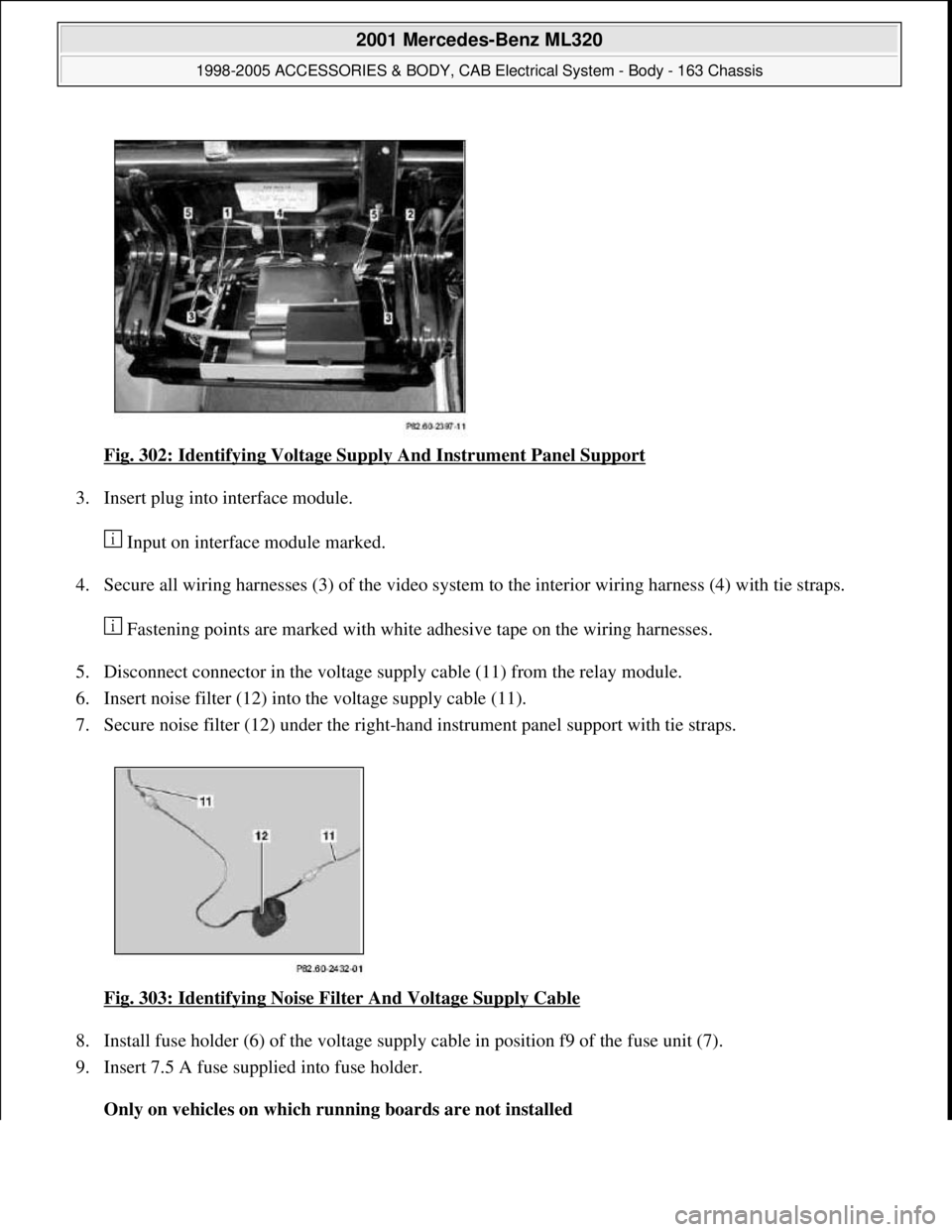
Fig. 302: Identifying Voltage Supply And Instrument Panel Support
3. Insert plug into interface module.
Input on interface module marked.
4. Secure all wiring harnesses (3) of the video system to the interior wiring harness (4) with tie straps.
Fastening points are marked with white adhesive tape on the wiring harnesses.
5. Disconnect connector in the voltage supply cable (11) from the relay module.
6. Insert noise filter (12) into the voltage supply cable (11).
7. Secure noise filter (12) under the right-hand instrument panel support with tie straps.
Fig. 303: Identifying Noise Filter And Voltage Supply Cable
8. Install fuse holder (6) of the voltage supply cable in position f9 of the fuse unit (7).
9. Insert 7.5 A fuse supplied into fuse holder.
Only on vehicles on which running boards are not installed
2001 Mercedes-Benz ML320
1998-2005 ACCESSORIES & BODY, CAB Electrical System - Body - 163 Chassis
me
Saturday, October 02, 2010 3:30:12 PMPage 387 © 2006 Mitchell Repair Information Company, LLC.
Page 2037 of 4133
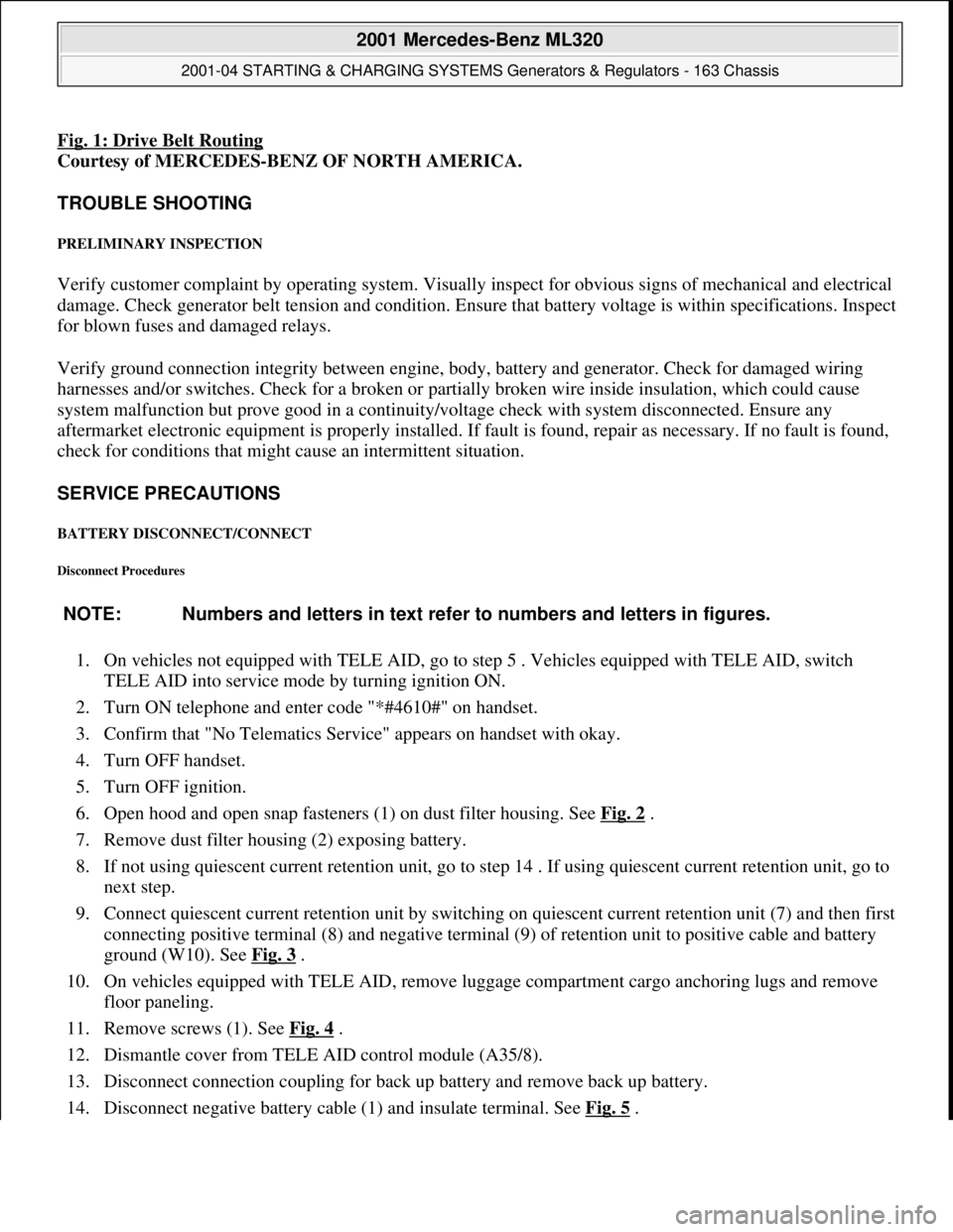
Fig. 1: Drive Belt Routing
Courtesy of MERCEDES-BENZ OF NORTH AMERICA.
TROUBLE SHOOTING
PRELIMINARY INSPECTION
Verify customer complaint by operating system. Visually inspect for obvious signs of mechanical and electrical
damage. Check generator belt tension and condition. Ensure that battery voltage is within specifications. Inspect
for blown fuses and damaged relays.
Verify ground connection integrity between engine, body, battery and generator. Check for damaged wiring
harnesses and/or switches. Check for a broken or partially broken wire inside insulation, which could cause
system malfunction but prove good in a continuity/voltage check with system disconnected. Ensure any
aftermarket electronic equipment is properly installed. If fault is found, repair as necessary. If no fault is found,
check for conditions that might cause an intermittent situation.
SERVICE PRECAUTIONS
BATTERY DISCONNECT/CONNECT
Disconnect Procedures
1. On vehicles not equipped with TELE AID, go to step 5 . Vehicles equipped with TELE AID, switch
TELE AID into service mode by turning ignition ON.
2. Turn ON telephone and enter code "*#4610#" on handset.
3. Confirm that "No Telematics Service" appears on handset with okay.
4. Turn OFF handset.
5. Turn OFF ignition.
6. Open hood and open snap fasteners (1) on dust filter housing. See Fig. 2
.
7. Remove dust filter housing (2) exposing battery.
8. If not using quiescent current retention unit, go to step 14 . If using quiescent current retention unit, go to
next step.
9. Connect quiescent current retention unit by switching on quiescent current retention unit (7) and then first
connecting positive terminal (8) and negative terminal (9) of retention unit to positive cable and battery
ground (W10). See Fig. 3
.
10. On vehicles equipped with TELE AID, remove luggage compartment cargo anchoring lugs and remove
floor paneling.
11. Remove screws (1). See Fig. 4
.
12. Dismantle cover from TELE AID control module (A35/8).
13. Disconnect connection coupling for back up battery and remove back up battery.
14. Disconnect ne
gative battery cable (1) and insulate terminal. See Fig. 5. NOTE: Numbers and letters in text refer to numbers and letters in figures.
2001 Mercedes-Benz ML320
2001-04 STARTING & CHARGING SYSTEMS Generators & Regulators - 163 Chassis
me
Saturday, October 02, 2010 3:20:31 PMPage 3 © 2006 Mitchell Repair Information Company, LLC.
Page 2038 of 4133
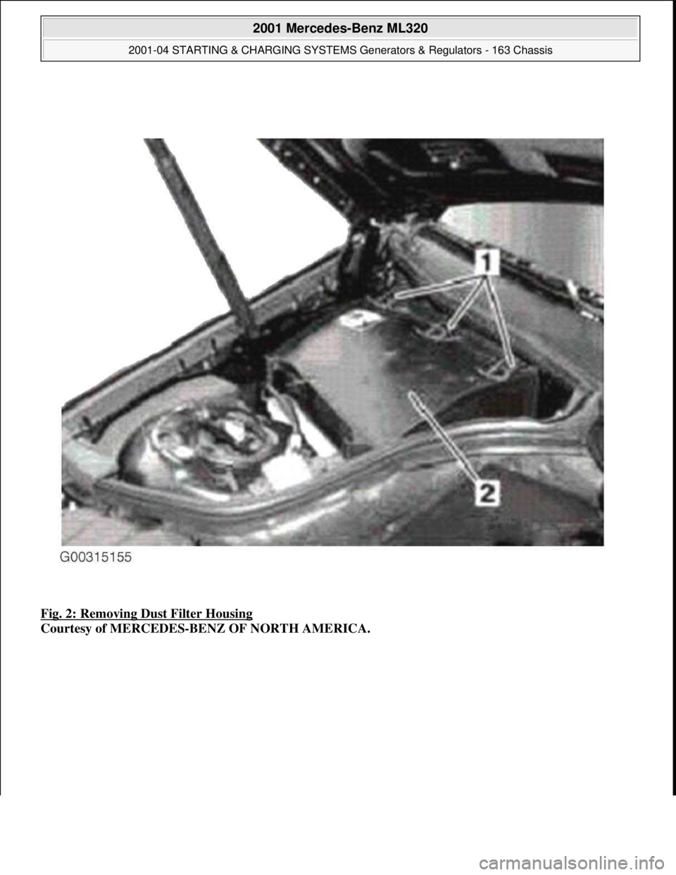
Fig. 2: Removing Dust Filter Housing
Courtesy of MERCEDES-BENZ OF NORTH AMERICA.
2001 Mercedes-Benz ML320
2001-04 STARTING & CHARGING SYSTEMS Generators & Regulators - 163 Chassis
me
Saturday, October 02, 2010 3:20:31 PMPage 4 © 2006 Mitchell Repair Information Company, LLC.
Page 2085 of 4133
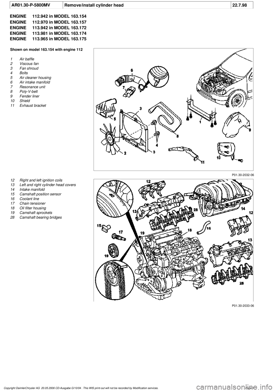
AR01.30-P-5800MV
Remove/install cylinder head
22.7.98
ENGINE
112.942 in MODEL 163.154
ENGINE
112.970 in MODEL 163.157
ENGINE
113.942 in MODEL 163.172
ENGINE
113.981 in MODEL 163.174
ENGINE
113.965 in MODEL 163.175
P01.30-2032-06
Shown on model 163.154 with engine 112
1
Air baffle
2
Viscous fan
3
Fan shroud
4
Bolts
5
Air cleaner housing
6
Air intake manifold
7
Resonance unit
8
Poly-V-belt
9
Fender liner
10
Shield
11
Exhaust bracket
P01.30-2033-06
12
Right and left ignition coils
13
Left and right cylinder head covers
14
Intake manifold
15
Camshaft position sensor
16
Coolant line
17
Chain tensioner
18
Oil filter housing
19
Camshaft sprockets
28
Camshaft bearing bridges
Copyright DaimlerChrysler AG 20.05.2006 CD-Ausgabe G/10/04 . This WIS print-out will not be recorde
d by Modification services.
Page 1